2ATI7STK-7024SSWITCH WIRELESS GAMEPAD
SHENZHEN SAITAKE ELECTRONIC CO.,LTD.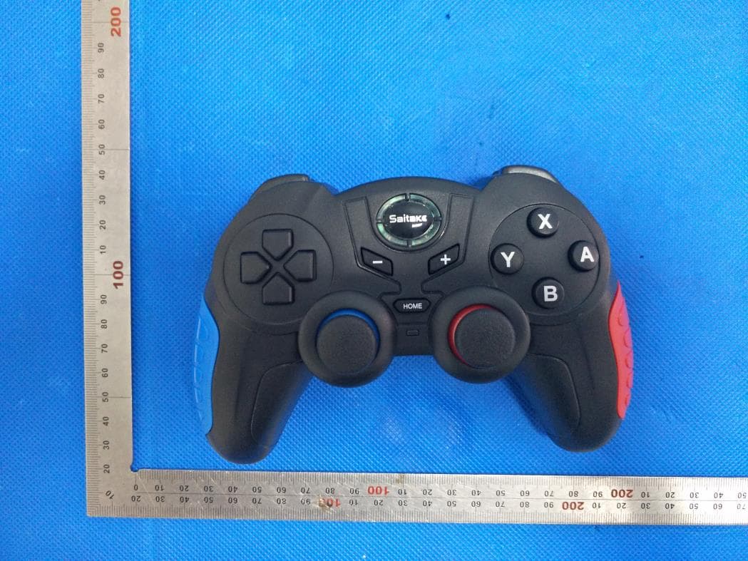
Click to zoom
Application Details
- Equipment Class
- DSS - Part 15 Spread Spectrum Transmitter
- Date of Grant
- Jul 26, 2020
- Application Purpose
- Original Equipment
- Date of Application
- Jul 26, 2020
- Equipment Note
- SWITCH WIRELESS GAMEPAD
- Frequency Range
- 2402.00000000 - 2480.00000000
- Country
- China
Documents & Files
Document Text
Text extracted from the exhibit documents filed with the FCC. Open a document above to read the original.
Users Manual
First Time to Pair & Connect 第1次オンライン Reconnect(HOME) 回連 Adjust Vibration Intensity 振動強度の調整 (Power on your console,then follow the steps to pair and connect your controller.) Step 1:Find Controllers Option.-Image1 Step 2:Click Change Grip/Order.-Image2 Step 3:Press Y+HOME button power on gamepad with 5 seconds till 4 LED lights flashes fastly,waiting for the connection to complete.-Image3 ステップ1:コントローラオプションを見つけよう。 ステッ プ2:クリック変化ている/ためのグリップ。 *Please make sure turn off the Airplane Mode when you connect controller to switch console. * コントローラーとコンソールの切り替えの际には、机能モードを确认してください. Reconnect:Press HOME Button If your controller was once paired and connected to your console,press the HOME button to rapidly connected next time. Note: For reconnectiong,please turn on the switch console firstly,does not support press HOME button to wake up the console under sleep mode. When one of the following conditions occur,please reconnect referring to first time to pair and connect. 1.Upgrade 2.Reset 3.You can not reconnect to console by pressing HOME button. 劇的な再接続:ホームボタンを押す コントローラがペアリングされ、スイッチコンソールに接続されている場合は、HOME ボタンを押して次回の接続を迅速に行います。 メモ: 再接続の場合は、まずスイッチコンソールの電源を入れてください、スリープモードで コンソールを起動するためにHOMEボタンを押すことをサポートしていません。 以下のいずれかの状況が発生した場合は、初めてペアリングして接続することを参照 して、劇的に再接続してください。 1. アップグレード 2. リセット 3.ホームボタンを押してコンソールに再接続することはできない。 There are 3 levels of vibration intensity:weak,moderate and strong Step 1: Please make sure you connect the controller to the switch console. Step 2: Press 4 buttons (L,ZL,R and ZR) simultaneously for 5 seconds. Step 3: Then release the 4 buttons when you feel the vibration. The vibration mode can be adjusted by repeating the above operatons. 振動強度の3つのレベルがあります:弱い、中程度と強い。 ステップ 1: コントローラーをスイッチ コンソールに接続していることを確認します。 ステップ2:4つのボタン(L、ZL、R、ZR)を同時に5秒間押します。 ステップ3:振動を感じたら4つのボタンを放します。 振動モードは、上記のオペラトンを繰り返すことで調整できます。 Use manuel 取扱説明書 STK-7024S STK-7024S ステップ3:4つのLEDライトが完全に点滅するまで、5秒でゲームパッドを押してく ださい(Y + Home)ボタンPower (コンソールの電源を入れたら、次に各ステップに従って、ペアリングしてコ ントローラーを接続する。)
Cover Letter(s)
Agent Authorization Company: SHENZHEN SAITAKE ELECTRONIC CO., LTD. Address: NO.1 1/F&3F, BLOCK 5, TIANFU'AN INDUSTRIAL PARK, LEZHUJIAO VILLAGE, HUANGMABU COMMUNITY, HANGCHENG STREET, BAO'AN DISTRICT, SHENZHEN, CHINA Product Name: SWITCH WIRELESS GAMEPAD Model Number(s): STK-7024S Product Description: SWITCH WIRELESS GAMEPAD We authorize MiCOM Labs Inc., 575 Boulder Court, Pleasanton, California 94566, USA, to act on our behalf on all matters concerning the certification of above named equipment. We declare that MiCOM Labs Inc. is allowed to forward all information related to the approval and certification of equipment to the regulatory agencies as required and to discuss any issues concerning the approval application. Any and all acts carried out by MiCOM Labs on our behalf shall have the same effect as acts of our own. Signature: Date: 2020-07-16 Name: Edwards Tong Company: SHENZHEN SAITAKE ELECTRONIC CO.,LTD
Cover Letter(s)
Office of Engineering Technology Federal Communications Commission 7435 Oakland Mills Road Columbia, MD 21046 USA Date: 2020-07-16 Subject; Request for Confidentiality FCC ID: 2ATI7STK-7024S To Whom It May Concern, Pursuant to the provisions of the Commission’s rules Title 47 Sections §0.457 and §0.459, we are requesting the Commission to withhold the following attachment(s) as confidential documents from public disclosure indefinitely. These documents contain detailed system and equipment descriptions and are considered as proprietary information in operation of the equipment. The public disclosure of these documents might be harmful to our company and would give competitors an unfair advantage in the market. Schematic Diagram Block Diagram Parts List Operational Description Tune-up Procedure In additional to above mentioned documents, in order to comply with the marketing regulations in Title 47 CFR §2.803 and the importation rules in Title 47 CFR §2.1204, while ensuring that business sensitive information remains confidential until the actual marketing of newly authorized devices, we request Short Term Confidentiality of the following attachment(s); External Photos Test Setup Photos Internal Photos User Manual For 45 days, pursuant to Public Notice DA 04-1705. OR For 180 days pursuant to KDB 726920 D01. It is our understanding that all measurement test reports, FCC ID label format and correspondence during the certification review process cannot be granted as confidential documents and this information will be available for public review once the grant of equipment authorization is issued. Sincerely, SHENZHEN SAITAKE ELECTRONIC CO., LTD. Contact person: Edwards Tong
External Photos
External Photos WHOLE VIEW OF EUT TOP VIEW OF EUT BOTTOM VIEW OF EUT FRONT VIEW OF EUT BACK VIEW OF EUT LEFT VIEW OF EUT RIGHT VIEW OF EUT VIEW OF EUT(PORT)
ID Label/Location Info
FCC ID Label Location 30mm*20mm FCC ID: 2ATI7STK-7024S
Internal Photos
Internal Photos OPEN VIEW OF EUT VIEW OF BATTERY INTERNAL VIEW OF EUT-1 INTERNAL VIEW OF EUT-2 INTERNAL VIEW OF EUT-3 INTERNAL VIEW OF EUT-4 INTERNAL VIEW OF EUT-5 INTERNAL VIEW OF EUT-6 INTERNAL VIEW OF EUT-7 BT Antenna
RF Exposure Info
RF EXPOSURE EVALUATION 1. PRODUCT INFORMATION Product Description SWITCH WIRELESS GAMEPAD Model Name STK-7024S FCC ID 2ATI7STK-7024S 2. EVALUATION METHOD According to 447498 D01 General RF Exposure Guidance v05 The 1-g and 10-g SAR test exclusion thresholds for 100 MHz to 6 GHz at test separation distances ≤ 50 mm are determined by: [(max. power of channel, including tune-up tolerance, mW)/(min. test separation distance, mm)] ·[√f(GHz)] ≤ 3.0 for 1-g SAR and ≤ 7.5 for 10-g extremity SAR. Where f(GHz) is the RF channel transmit frequency in GHz Power and distance are rounded to the nearest mW and mm before calculation 3. CALCULATION BR/EDR: P t = 0.389dBm=1.09mW The value of the Maximum output power P t is referred to the test report of the CFR47 §15.247. The result for RF exposure evaluation SAR=(1.09mW /5mm) .[√2.480GHz)]=0.34<3.0 for 1-g SAR and ≤ 7.5 for 10-g extremity SAR. 4. CONCLUSION The SAR evaluation is not required.
Test Report
Page 1 of 67 FCC Test Report Report No.: AGC00025200402FE03 FCC ID : APPLICATION PURPOSE : Original Equipment PRODUCT DESIGNATION : SWITCH WIRELESS GAMEPAD BRAND NAME : N/A MODEL NAME : STK-7024S APPLICANT : SHENZHEN SAITAKE ELECTRONIC CO.,LTD DATE OF ISSUE : Jun. 30, 2020 STANDARD(S) : FCC Part 15.247 REPORT VERSION : V1.0 Attestation of Global Compliance (Shenzhen) Co., Ltd CAUTION: This report shall not be reproduced except in full without the written permission of the test laboratory and shall not be quoted out of context. Report No.: AGC00025200402FE03 Page 2 of 67 REPORT REVISE RECORD Report Version Revise Time Issued Date Valid Version Notes V1.0 / Jun. 30, 2020 Valid Initial Release Report No.: AGC00025200402FE03 Page 3 of 67 TABLE OF CONTENTS 1. VERIFICATION OF CONFORMITY ............................................................................................................... 5 2. GENERAL INFORMATION ............................................................................................................................ 6 2.1. PRODUCT DESCRIPTION ..................................................................................................................... 6 2.2. TABLE OF CARRIER FREQUENCYS ..................................................................................................... 6 2.3. RECEIVER INPUT BANDWIDTH ............................................................................................................ 7 2.4. EXAMPLE OF A HOPPING SEQUENCY IN DATA MODE ....................................................................... 7 2.5. EQUALLY AVERAGE USE OF FREQUENCIES AND BEHAVIOUR ........................................................ 7 2.6. RELATED SUBMITTAL(S) / GRANT (S) .................................................................................................. 8 2.7. TEST METHODOLOGY .......................................................................................................................... 8 2.8. SPECIAL ACCESSORIES ....................................................................................................................... 8 2.9. EQUIPMENT MODIFICATIONS .............................................................................................................. 8 3. MEASUREMENT UNCERTAINTY ................................................................................................................. 9 4. DESCRIPTION OF TEST MODES ............................................................................................................... 10 5. SYSTEM TEST CONFIGURATION ............................................................................................................. 11 5.1. CONFIGURATION OF EUT SYSTEM .................................................................................................... 11 5.2 EQUIPMENT USED IN TESTED SYSTEM .............................................................................................. 11 5.3. SUMMARY OF TEST RESULTS ............................................................................................................. 11 6. TEST FACILITY ........................................................................................................................................... 12 7. PEAK OUTPUT POWER ............................................................................................................................. 13 7.1. MEASUREMENT PROCEDURE ........................................................................................................... 13 7.2. TEST SET-UP (BLOCK DIAGRAM OF CONFIGURATION) ................................................................... 13 7.3. LIMITS AND MEASUREMENT RESULT ............................................................................................... 14 8. 20DB BANDWIDTH ..................................................................................................................................... 18 8.1. MEASUREMENT PROCEDURE ........................................................................................................... 18 8.2. TEST SET-UP (BLOCK DIAGRAM OF CONFIGURATION) ................................................................... 18 8.3. LIMITS AND MEASUREMENT RESULTS ............................................................................................. 19 9. CONDUCTED SPURIOUS EMISSION ........................................................................................................ 23 9.1. MEASUREMENT PROCEDURE ........................................................................................................... 23 9.2. TEST SET-UP (BLOCK DIAGRAM OF CONFIGURATION) ................................................................... 23 9.3. MEASUREMENT EQUIPMENT USED .................................................................................................. 23 Report No.: AGC00025200402FE03 Page 4 of 67 9.4. LIMITS AND MEASUREMENT RESULT ............................................................................................... 23 10. RADIATED EMISSION ............................................................................................................................... 34 10.1. MEASUREMENT PROCEDURE ......................................................................................................... 34 10.2. TEST SETUP ....................................................................................................................................... 36 10.3. LIMITS AND MEASUREMENT RESULT ............................................................................................. 37 10.4. TEST RESULT ..................................................................................................................................... 37 11. NUMBER OF HOPPING FREQUENCY ..................................................................................................... 47 11.1. MEASUREMENT PROCEDURE ..........…
Text truncated - open the document above for the full version.
Test Report
Report No.: AGC00025200402FE03 Page 58 of 67 CONDUCTED EMISSION TEST SETUP Report No.: AGC00025200402FE03 Page 59 of 67 APPENDIX B: PHOTOGRAPHS OF EUT WHOLE VIEW OF EUT TOP VIEW OF EUT Report No.: AGC00025200402FE03 Page 60 of 67 BOTTOM VIEW OF EUT FRONT VIEW OF EUT Report No.: AGC00025200402FE03 Page 61 of 67 BACK VIEW OF EUT LEFT VIEW OF EUT Report No.: AGC00025200402FE03 Page 62 of 67 RIGHT VIEW OF EUT VIEW OF EUT(PORT) Report No.: AGC00025200402FE03 Page 63 of 67 OPEN VIEW OF EUT VIEW OF BATTERY Report No.: AGC00025200402FE03 Page 64 of 67 INTERNAL VIEW OF EUT-1 INTERNAL VIEW OF EUT-2 Report No.: AGC00025200402FE03 Page 65 of 67 INTERNAL VIEW OF EUT-3 INTERNAL VIEW OF EUT-4 Report No.: AGC00025200402FE03 Page 66 of 67 INTERNAL VIEW OF EUT-5 INTERNAL VIEW OF EUT-6 Report No.: AGC00025200402FE03 Page 67 of 67 INTERNAL VIEW OF EUT-7 ----END OF REPORT---- BT Antenna
Test Setup Photos
Test Setup Photos RADIATED EMISSION TEST SETUP BELOW 1GHZ RADIATED EMISSION TEST SETUP ABOVE 1GHZ CONDUCTED EMISSION TEST SETUP
Contact Information
Applicant
Edwards Tong
Technical Contact
Test Firm
Attestation of Global Compliance (Shenzhen) Co., LDoris Li
[email protected]+86-755-25234088
Technical Specifications
| # | Rule Parts | Frequency Range | Power Output |
|---|---|---|---|
| 1 | 15C | 2.40 GHz - 2.48 GHz | 1.10 mW |
Other Applications from SHENZHEN SAITAKE ELECTRONIC CO.,LTD.
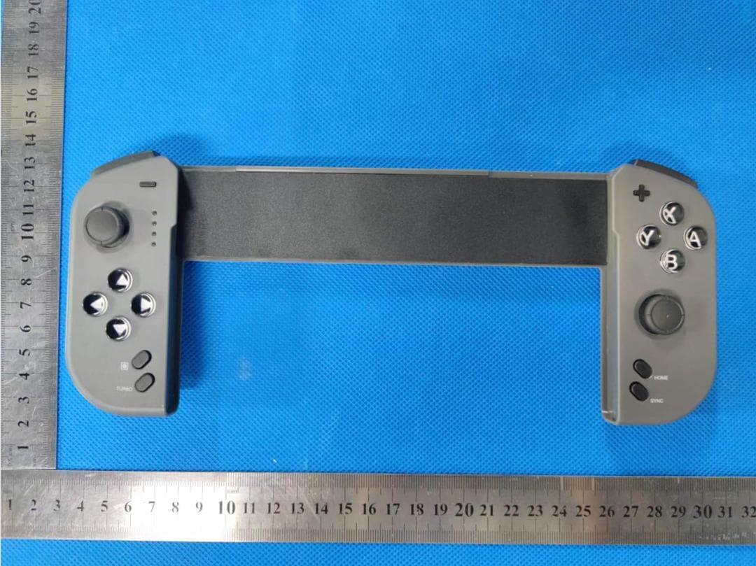
2ATI7STK-7046
Jul 03, 2023Protable Wireless Joypad
Equipment Class
DSS - Part 15 Spread Spectrum Transmitter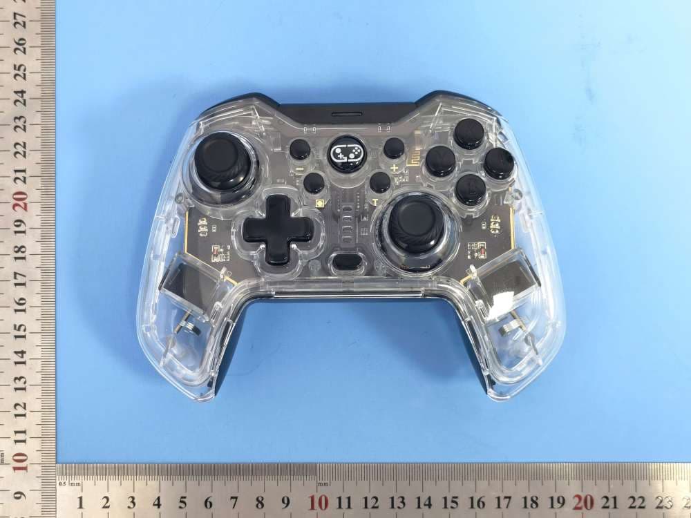
2ATI7STK-7040RG
Aug 13, 2022Wireless Controller
Equipment Class
DTS - Digital Transmission System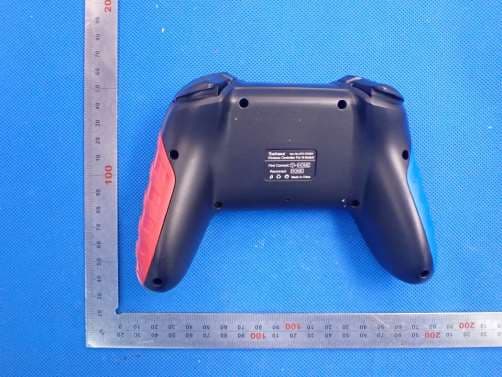
2ATI7STK-7033SN
Oct 13, 2020SWITCH WIRELESS GAMEPAD
Equipment Class
DSS - Part 15 Spread Spectrum Transmitter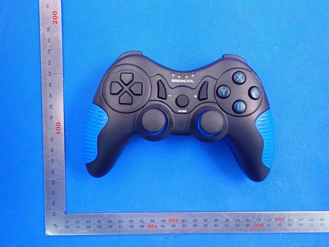
2ATI7STK-7021S
Sep 23, 2020SWITCH WIRELESS GAMEPAD
Equipment Class
DSS - Part 15 Spread Spectrum Transmitter