2AU29AMP25BDCV3DC Tubular Motor for Narrow Shades
Turnils North America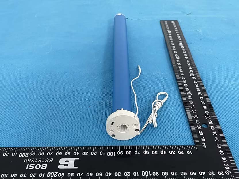
Click to zoom
Application Details
- Equipment Class
- DSC - Part 15 Security/Remote Control Transmitter
- Date of Grant
- Jul 09, 2023
- Application Purpose
- Original Equipment
- Date of Application
- Jul 09, 2023
- Equipment Note
- DC Tubular Motor for Narrow Shades
- Frequency Range
- 433.92500000 - 433.92500000
- Company
- Turnils North America
- Country
- United States
Documents & Files
Document Text
Text extracted from the exhibit documents filed with the FCC. Open a document above to read the original.
Users Manual
AMP25B Instruction Attention -1- The motor is suitable for motorization of roller blinds, sheer shadings, roman shades, and zebra shades. Never drop, knock, drill or submerge the motor. Keep the power cable in right position as following. Important safety instructions to be read before installation. Incorrect installation can lead to serious injury and will void manufacturer’s liability and warranty. Declarations Do not dispose of in general waste. Please recycle batteries and damaged electrical products appropriately. -2- Safety 1. Do not expose motor to humid, damp or extreme temperature conditions. 2. Do not drill into motor. 3. Do not cut the antenna and keep it clear from metal objects. 4. Do not allow children to play with this device. 5. If power cable or connector is damaged, do not use. 6. Ensure correct crown and drive adaptor are used. 7. Ensure power cable and aerial is clear and protected from moving parts. 8. Cable routed through walls shall be properly isolated. 9. Motor is to be mounted in horizontal position only. 10. Before installation, remove unnecessary cords and disable equipment not needed for powered operation. 11. Installation and programming to be performed by a qualified professional, use or modification outside the scope of this instruction may void warranty. Features Fields of Application Specifications Following data for reference Working temperature: -10°C ~ +50°C Input Voltage: USB 5V 1A / USB 5V 2A Radio Frequency: 433.925MHz Maximum Running Time: 6 minutes Model Rated Torque (N.m) Rated Speed (rpm) Rated Power (W) AMP25B - 0.7/340.7348 AMP25B -1.1/281.1288 Charging Instructions This motor has a built in Li-ion battery pack with integrated charge management. Max power input for recharging: 5V 2A. Before first use please charge motor for 6 hours. Using 5V charger (most phones charger is 5V ) . During operation, when the motor starts, the buzzer will beep 10 times, indicating a low-voltage alarm and needs to be charged. During operation, the voltage was detected to be too low, the battery was about to run out, the battery stopped running and needed to be recharged. Rechargeable Battery Blinking red: Low battery alert Blinking green: Charging is processing Solid green: Battery has finished charging. FCC Text - text 01 Add A zoom in on the charging port P1 Button Instructions P1 button Lithium Battery Switch LED light Micro-USB Port Add visual explanation of P1 - file 02 Sheer Roller Revolve Roman shades Working temperature: -10º C ~ +50º CRadio Frequency: 433.925 MHz Input Voltage: USB 5V 1A / USB 5V 2AMaximum Running Time: 6 minutes Model Rated Torque (N.m) Rated Speed (RPM) Rated Power (W) 25BDC - 1.1/281.12812 SettingsSteps 1PairingP1 (hold down for 2s) > Stop (hold down for 2s) 2Switch Rotating DirectionUp + Down (hold down for 2s) 3Setting Upper & Lower Limits 4Add / Remove Favorite PositionP2 > Stop > Stop 5Roller Mode & Sheer Mode SwitchUp + Down (hold down for 5s) > Stop 6Adjust Limits 7Pair / Unpair Additional EmitterP2 (existing) > P2 (existing) > P2 (new) 8Speed Regulation IssuesPossible CausesSolution External battery pack is depleted Recharge with compatible AC adaptor and check connection and positioning of solar PV panel Insufficient charging from Solar PV Panel Check connection and orientation of solar PV panel Remote control battery is dischargedReplace battery Battery is inserted incorrectly into remote control Check battery polarity The motor is not respondingRadio interference / shielding Ensure remote control and the antenna on the motor are positioned away from metal objects Receiver is far away from Remote Control Move remote control to a closer position Power failureCheck power supply to motor is connected and active Incorrect wiring Check that wiring is connected correctly (refer to motor installation instructions) Motor beeps 10 times when in use Battery voltage is low / PV (solar panel issue) Recharge with AC adapter or check connection and positioning of solar PV panel Always reserve an individual channel for programming functions SYSTEM BEST PRACTICE - Provide an extra 15 channel remote in your multi-motor projects that provides individual control for each motor for programming purposes Place all other motors into sleep mode (ref to P1 button instructions) The motor is suitable for motorization of roller shades, sheer shades, roman shades, and revolve shades. Do not dispose of in general waste. Please recycle batteries and damaged electrical products appropriately. RollerSheerBandedRomanNarrow Upper Limit: Up (hold down for 2s) > Up + Stop (hold down for 2s) Upper Limit: Up + Stop (hold down for 5s) > Up or Down > Up + Stop (hold down for 2s) Cannot program a single motor (multiple motors respond) Multiple motors are paired to the same channel. Acceleration: P2 > Up > Up Lower Limit: Down (hold down for 2s) > Down + Stop (hold down for 2s) Lower Limit: Down + Stop (hold down for 5s) > Up or Down > Down + Stop (hold down for 2s) Deceleration: P2 > Down > Down Please scan QR code to see more AMP ™ product information 1 2 3 4 ×××× 5 Test Motor 1 2 6 10 14 Activate Pairing Mode Sleep Mode Reverse Direction Reset To Factory Settings Approx. 2 sec. Happening as you press for 2 seconds Happening as you press for 1 second Happening as you press for 6 seconds Happening as you press for 10 seconds Happening as you press for 14 seconds when released when released when released when released when released Approx. 6 sec. Approx. 10 sec. Approx. 14 sec. Until Shade: Until Shade: Motor Response: Motor Response: Motor Response: Until Shade: Until Shade: Motor Response: Beep x1 Beep x2 Jog x3 Jog x4 Jog x1 Jog x2 Beep x3 Beep x4 Less than 1 sec. Press P1 Press P1 Press P1 Press P1 Press P1 Motor Response: Wakes & Runs AMP25BDC Declarations Fields of Application Specifications Quick Index Attention Safety Instructions Troubleshooting Charging Instructions P1 Button Instructions Never drop, knock, drill or submerge the motor. Keep the power cable i…
Text truncated - open the document above for the full version.
Users Manual
! Essential Settings The steps in factory mode must be completed to ensure proper operation. 7. Add or Remove Additional Remote 8. Adjust Motor Speed 6. Roller Mode and Sheer Mode 4. Adjust Limits 2. Change Motor Direction (if necessary) 3. Setting the Upper and Lower Limits 1. Pair / Unpair Remote Control Button Instructions Jog x1 Jog x1 Jog x2 Beep x1 Beep x1 Beep x3 LED light P1 button Lithium Battery Switch a. Press “P1” button (about 2 sec) on the motor head until motor jog x1 and beep x1. b. In the next 10 secs, press and hold “Stop” button on the remote control until motor jog x2 and beep x3. 4.1 Adjust the Upper Limit 6.1 Roller Shade Mode - continue movement after a short pr ess - Default Mode a. Press and hold (about 5 sec) “Up” and “Down” buttons simultaneously until motor jog x1. b. Press and hold (about 2 sec) “Stop” button until motor jog x2 and beep x3. 7.1 Using Current Remote Control a. On the current remote control, press one “P2” button until motor jog x1 and beep x1. b. Once more, on the current remote control, press one “P2” button until motor jog x1 and beep x1. c. On the New remote control, press one “P2” button until motor jog x2 and beep x3. 8.1 Acceleration Speed a. Press one “P2” button until motor jog x1 and beep x1. b. Press “Up” button until motor jog x1 and beep x1. c. Once more, press “Up” button until motor jog x2 and beep x1. 6.2 Sheer Shade Mode - jog movement after a short press (continue movement after a long press) a. Press and hold (about 5 sec) “Up” and “Down” buttons simultaneously until motor jog x1. b. Press and hold (about 2 sec) “Stop” button until motor jog x1 and beep x1. 8.2 Deceleration Speed a. Press one “P2” button until motor jog x1 and beep x1. b. Press “Down” button until motor jog x1 and beep x1. c. Once more, press “Down” button until motor jog x2 and beep x1. 5.1 Set Favorite Position a. Use “Up” or “Down” button to move the shade to desired Favorite position. b. Press one “P2” button on the back of remote control until motor jog x1 and beep x1. c. Press and hold (about 2 sec) “Stop” button until motor jog x1 and beep x1. d. Once more, press and hold (about 2 sec) “Stop” button until motor jog x2 and beep x3. 5.3 Delete Favorite Position a.Press one “P2” button until motor jog and beep x1. b.Press and hold (about 2 sec) “Stop” button until motor jog and beep x1. c.Once more, press and hold (about 2 sec) “Stop” button until motor jog x1 and long beep x1. 4.2 Adjust the Lower Limit 5.2 Send Shade to Favorite Position Press and hold (about 2 sec) “Stop” button, motor will move to Favorite position. Press “Up” or “Down” button to check if the shade moves in the desired direction. If you need to reverse the direction, press and hold (about 2 sec) “Up” and “Down” buttons simultaneously until motor jog x1 and beep x1. 3.1 Set Upper Limit *The operation is only valid when there are no limits. If the motor has already set the upper and lower limit, then you can only switch direction by pressing P1 button (See P1 button instructions). * Repeat the same procedure to unpair remote control. *If you exit the limit setting status before you finish the limit settings, the motor will take the previous existing limits. *If the motor has no response, it already has a Maximum or Minimum speed. *Repeat the same procedure to remove additional remote control. Action on Motor Action on Remote Control + Action on Remote Control Action on Remote Control Action on Remote Control Motor Response Motor Response Motor Response Motor Response Motor Response Stop UpDown LCD Display Up Stop Down P2 Switch P2 P1 a. a. a. a. a. a. b. b. b. a.b. a. a. c. b. b. b. b. c. c. b. c. c. c. c. d. Jog x2 Jog x2 Beep x3 Beep x3 + + Up Up Down Stop Stop Down a. a. b. a. b. b. Jog x1 Jog x2 Beep x1 Beep x3 + + Up Up Up Stop Action on Remote Control Action on Remote Control Action on Remote Control Motor Response Motor Response Motor Response Stop Jog x1 Beep x1 + DownStop Down Jog x2 Beep x3 + DownStop Jog x1 Jog x2 Beep x3 + UpDown Stop Action on Remote Control Action on Remote Control Motor Response Motor Response Jog x1 Jog x1 Beep x1 Action on Remote Control Action on Remote Control Motor Response Motor Response + UpDown Stop Jog x1 Jog x2 Jog x1 Beep x1 Beep x3 Beep x1 Current Remote Control New Remote Control Current Remote Control Action on Remote Control Action on Remote Control Motor Response Motor Response P2 P2 P2 Jog x1 Jog x1Jog x1 Jog x2 Jog x1 Jog x2 Beep x1 Beep x1Beep x1 Beep x1 Beep x1 Beep x1 Up Up Down Down Action on Remote Control Action on Remote Control Action on Remote Control Action on Remote Control Motor Response Motor Response Motor Response Motor Response P2 P2 Higher Channel Lower Channel 7.2 New Remote Control Follow instructions under the section 1. Pair / Unpair Remote Control Action on Remote Control Motor Response Jog x1 Jog x1Jog x2 Beep x1 Beep x1Beep x3 Jog x1 Jog x1 Jog x1 Beep x1 Beep x1 Beep x1 or or or UpDown Stop Stop Stop Stop Stop Action on Remote Control Action on Remote Control Action on Remote Control Action on Remote Control Action on Remote Control Motor Response Shade Response Motor Response Motor Response Motor Response P2 P2 a. Press “Up” button to raise the shade, then press “Stop” button when it is in the desired upper limit. b. Press and hold (about 2 sec) “Up” and “Stop” buttons simultaneously until motor jog x2 and beep x3. 3.2 Set Lower Limit a. Press “Down” button to lower the shade, then press “Stop” button when it is in the desired lower limit. b. Press and hold (about 2 sec) “Down” and “Stop” buttons simultaneously until motor jog x2 and beep x3. a. Press and hold (about 5 sec) “Up” and “Stop” buttons simultaneously until motor jog x1 and beep x1. b. Use “Up” button to raise the shade to the desired highest position, and use “Up” or “Down” button to do the final adjustment if necessary. c. Press and hold (about 2 sec) “Up” and “Stop” buttons simultaneously until motor jog x2 and beep x3. a. Press and hold (about 5 s…
Text truncated - open the document above for the full version.
Attestation Statements
C ompany name: Turnils North America Address: 1750 Satellite Blvd, Suite 100, Buford, Georgia, United States 30518 Tel: 770-878-2281 Fax: 770-995-2210 Email: [email protected] CFR 47 §2.911(d)(5)(i)(ii) Attestation Letter Attestation Letter Date: 06/12/2023 FEDERAL COMMUNICATIONS COMMISSIONS Authorization and Evaluation Division 7435 Oakland Mills Road Columbia, MD 21046 Ref: Attestation Statements CFR 47 §2.911(d)(5)(i)(ii) Filing FCC ID: 2AU29AMP25BDCV3 Turnils North America (“the applicant”) certifies that the equipment for which authorization is sought is not “covered” equipment prohibited from receiving an equipment authorization pursuant to section 2.903 of the FCC rules. Turnils North America ( “the applicant”) certifies that as of the date of the filing of the application, the applicant is not identified on the Covered List as an entity producing “covered” equipment. Sincerely, Signature Contact Person: Phoenix Lin Title: Senior Project Manager
Attestation Statements
U.S. AGENT LETTER OF ATTESTATION Date: 2023-06-12 FEDERAL COMMUNICATIONS COMMISSION Authorization and Evaluation Division 7435 Oakland Mills Road Columbia, MD 21046 Ref: Attestation Statements Part 2.911(d)(7) Filing FCC ID: 2AU29AMP25BDCV3 T urnils North America (“the Applicant”) certifies that, as of the date of the filing of the application, Turnils North America (U.S. agent). is our designated U.S. agent for service of process for the above referenced FCC ID. Turnils North America (“the Applicant”) accepts to maintain an agent for no less than one year after the grantee has terminated all marketing and importation or the conclusion of any Commission-related proceeding involving the equipment. Turnils North America (U.S. agent) accepts, as of the date of the filing of the application, the obligation of the designated U.S. agent for service of process for the above referenced FCC ID. Designated U.S. Agent and Applicant Information: Company Name: Turnils North America Address: 1750 Satellite Blvd, Suite 100, Buford, Georgia, United States 30518 FRN: 0028959575 Tel.: 770-878-2281 Email: [email protected] Signed by (printed name): Phoenix Lin Signature: CFR 47 §2.911(d)(7) U.S Agent
Cover Letter(s)
Company name: Turnils North America Address: 1750 Satellite Blvd, Suite 100, Buford, Georgia, United States 30518 Tel: 770-878-2281 Fax: 770-995-2210 Email: [email protected] FCC Authorization Date:2023-06-12 FEDERAL COMMUNICATIONS COMMISSION Authorization and Evaluation Division 7435 Oakland Mills Road Columbia, MD 21046 Subject: Agent Authorization To whom it may concern: We, Turnils North America, Hereby authorizes CHINA CERTIFICATION ICT CO., LTD (DONGGUAN) to ac t on its behalf in all matters relating to ap plication for Equipment authorization, including the signing of all documents relating to these matters. All acts carried out by CHINA CERTIFICATION ICT CO., LTD (DONGGUAN) on our behalf shall have t he same ef fect as our own action. We, the undersigned, hereby certify that we ar e not subject to a denial of federal benefits, that includes FCC benefits, pursuan t to Section 5301 of the Anti-Drug Abuse Act of 1988, 21 U.S.C. 862. Th is a uthorization is valid until further written notice from the applicant. Sincer ely Yours, Signature: Printed Name: Phoenix Lin Title: Senior Project Manager QA-FR-170-B
Cover Letter(s)
QA-FR-171-A Company name: Turnils North America Address: 1750 Satellite Blvd, Suite 100, Buford, Georgia, United States 30518 Tel: 770-878-2281 Fax: 770-995-2210 Email: [email protected] FCC Confidential Authorization Date: 2023-06-12 FEDERAL COMMUNICATIONS COMMISSIONS Authorization and Evaluation Division 7435 Oakland Mills Road Columbia, MD 21046 Subject: Confidentiality Request regarding application for certification of FCC ID: 2AU29AMP25BDCV3 In accordance with Sections 0.457 and 0.459 of the Commission’s Rules, Turnils North America hereby requests long-term confidential treatment of information accompanying this application as outlined below: • Block Diagram • Schematics • Operation Description The above materials contain proprietary and confidential information not customarily released to the public. The public disclosure of these materials provides unjustified benefits to its competitors in the market. Sincerely, Signature: Printed Name: Phoenix Lin Title: Senior Project Manager
External Photos
EXHIBIT B - EUT EXTERNAL PHOTOGRAPHS
ID Label/Location Info
1.Label 2.Label Location
Internal Photos
EXHIBIT C - EUT INTERNAL PHOTOGRAPHS Uncover Antenna
RF Exposure Info
China Certification ICT Co., Ltd (Dongguan) Report No.: CR230206425-00C Page 34 of 34 5. RF EXPOSURE EVALUATION 5.1 Applicable Standard FCC §1.1307(b)(3)(i)(A) a single RF source is exempt RF device (from the requirement to show data demonstrating compliance to RF exposure limits, as previously mentioned) if the available maximum time-averaged power is no more than 1 mW, regardless of separation distance. 5.2 Procedure According to 447498 D04 Interim General RF Exposure Guidance v01, clause 2.1.2- 1-mW Test Exemption: Per §1.1307(b)(3)(i)(A), a single RF source is exempt RF device (from the requirement to show data demonstrating compliance to RF exposure limits, as previously mentioned) if the available maximum time-averaged power is no more than 1 mW, regardless of separation distance. This exemption applies to all operating configurations and exposure conditions, for the frequency range 100 kHz to 100 GHz, regardless of fixed, mobile, or portable device exposure conditions. This is a standalone exemption, and it cannot be applied in conjunction with any other test exemption. 5.3 Measurement Result Frequency (MHz) Maximum ERP Power 1-mW Test Exemption dBm mW 433.925 -10.03 0.1 Compliant Note: 1. Chose the maximum power to do MPE analysis. 2. This device maximum E - Field level is 87.32 dBμV/m at 3m, so the EIRP power is -7.88dBm. 3. EIRP(dBm) = Field Strength of Fundamental(dBuV/m)-95.2 4. ERP = EIRP – 2.15 dB Result: Compliant. RF Exposure is exemption. ===== END OF REPORT =====
Test Report
TEST REPORT Applicant: Turnils North America Address: 1750 Satellite Blvd, Suite 100, Buford, Georgia, United States 30518 FCC ID: 2AU29AMP25BDCV3 Product Name: DC Tubular Motor for Narrow Shades Standard(s): 47 CFR Part 15, Subpart C(15.231) ANSI C63.10-2013 The above equipment has been tested and found compliance with the requirement of the relative standards by China Certification ICT Co., Ltd (Dongguan) Report Number: CR230206425-00C Date Of Issue: 2023/4/6 Reviewed By: Sun Zhong Title: Manager Test Laboratory: China Certification ICT Co., Ltd (Dongguan) No. 113, Pingkang Road, Dalang Town, Dongguan, Guangdong, China Tel: +86-769-82016888 China Certification ICT Co., Ltd (Dongguan) Report No.: CR230206425-00C Page 2 of 34 Test Facility The Test site used by China Certification ICT Co., Ltd (Dongguan) to collect test data is located on the No. 113, Pingkang Road, Dalang Town, Dongguan, Guangdong, China. The lab has been recognized as the FCC accredited lab under the KDB 974614 D01 and is listed in the FCC Public Access Link (PAL) database, FCC Registration No. : 442868, the FCC Designation No. : CN1314. The lab has been recognized by Innovation, Science and Economic Development Canada to test to Canadian radio equipment requirements, the CAB identifier: CN0123. Declarations China Certification ICT Co., Ltd (Dongguan) is not responsible for the authenticity of any test data provided by the applicant. Data included from the applicant that may affect test results are marked with a triangle symbol “▲”. Customer model name, addresses, names, trademarks etc. are not considered data. Unless otherwise stated the results shown in this test report refer only to the sample(s) tested. This report cannot be reproduced except in full, without prior written approval of the Company. This report is valid only with a valid digital signature. The digital signature may be available only under the Adobe software above version 7.0. This report may contain data that are not covered by the accreditation scope and shall be marked with an asterisk “★”. China Certification ICT Co., Ltd (Dongguan) Report No.: CR230206425-00C Page 3 of 34 CONTENTS T EST FACILITY .......................................................................................................................................... 2 DECLARATIONS .......................................................................................................................................... 2 DOCUMENT REVISION HISTORY .......................................................................................... 5 1. GENERAL INFORMATION .................................................................................................... 6 1.1 PRODUCT DESCRIPTION FOR EQUIPMENT UNDER TEST (EUT) ....................................................... 6 1.2 DESCRIPTION OF TEST CONFIGURATION ........................................................................................... 7 1.2.2 Support Equipment List and Details .............................................................................................................. 7 1.2.3 Support Cable List and Details ...................................................................................................................... 7 1.2.4 Block Diagram of Test Setup ......................................................................................................................... 7 1.3 MEASUREMENT UNCERTAINTY .......................................................................................................... 9 2. SUMMARY OF TEST RESULTS .......................................................................................... 10 3. REQUIREMENTS AND TEST PROCEDURES .................................................................. 11 3.1 AC LINE CONDUCTED EMISSIONS .................................................................................................... 11 3.1.1 Applicable Standard ..................................................................................................................................... 11 3.1.2 EUT Setup.................................................................................................................................................... 12 3.1.3 EMI Test Receiver Setup ............................................................................................................................. 12 3.1.4 Test Procedure ............................................................................................................................................. 13 3.1.5 Corrected Amplitude & Margin Calculation ................................................................................................ 13 3.2 RADIATION SPURIOUS EMISSIONS .................................................................................................... 14 3.2.1 Applicable Standard ..................................................................................................................................... 14 3.2.2 EUT Setup.................................................................................................................................................... 15 3.2.3 EMI Test Receiver & Spectrum Analyzer Setup ......................................................................................... 15 3.2.4 Test Procedure ............................................................................................................................................. 15 3.2.5 Corrected Amplitude & Margin Calculation ................................................................................................ 16 3.3 20 DB EMISSION BANDWIDTH: .......................................................................................................... 17 3.3.1 Applicable Standard ..................................................................................................................................... 17 3.3.2 EUT Setup...........................…
Text truncated - open the document above for the full version.
Test Setup Photos
EXHIBIT D - TEST SETUP PHOTOGRAPHS Conducted Emissions Front View Conducted Emissions Side View Radiated Emission Below 1GHz View Radiated Emission Above 1GHz View
Contact Information
Applicant
Phoenix Lin(Senior Project Manager)
Test Firm
CHINA CERTIFICATION ICT CO., LTD (DONGGUAN)Tanie Ou
[email protected]0086 0769 86858888
Technical Specifications
| # | Rule Parts | Frequency Range | Power Output |
|---|---|---|---|
| 1 | 15.231 | 433.925 MHz - 433.925 MHz | - |
Other Applications from Turnils North America
2AU29AMPSNHUBV1
Jan 18, 2024Smart Hub
Equipment Class
DSC - Part 15 Security/Remote Control Transmitter2AU29AMPSNHUBFV1
Jan 18, 2024Smith & Noble Smart Hub
Equipment Class
DSC - Part 15 Security/Remote Control Transmitter2AU29AMPRFWIFIUSBV3
Jan 16, 2024AMP Bridge
Equipment Class
DSC - Part 15 Security/Remote Control Transmitter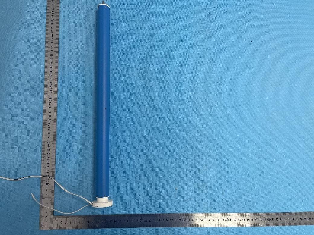
2AU29AMP28BDCV2
Dec 16, 2023DC Tubular Motor with built-in RF control
Equipment Class
DSR - Part 15 Remote Control/Security Device Transceiver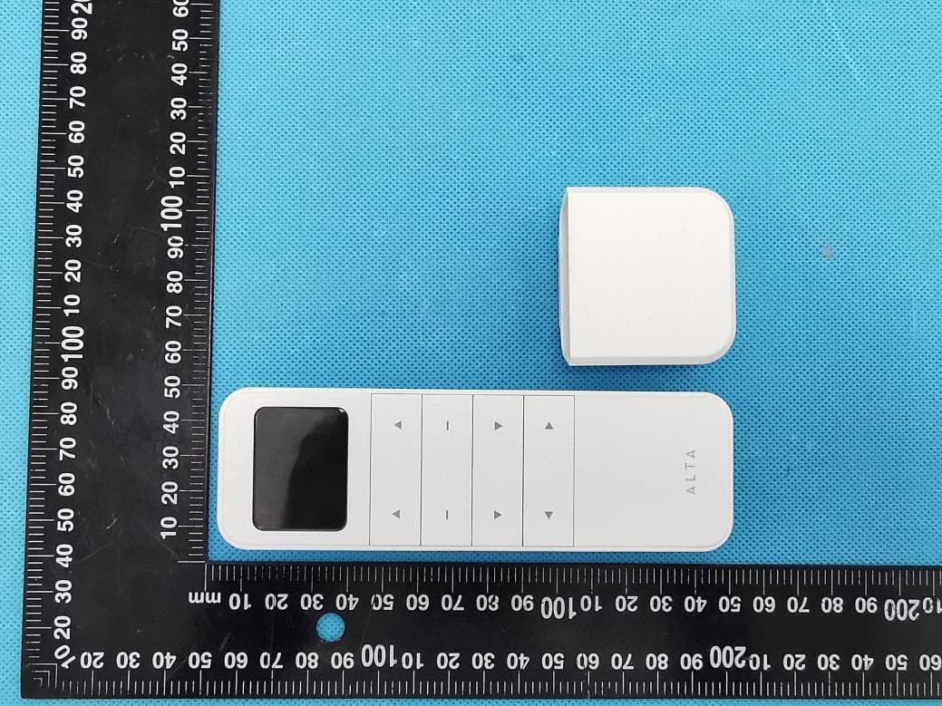
2AU29ALATAAAARE
Jul 01, 2023Remote
Equipment Class
DSC - Part 15 Security/Remote Control Transmitter