2AU29AMPRFWIFIUSBAMP Bridge
Turnils North America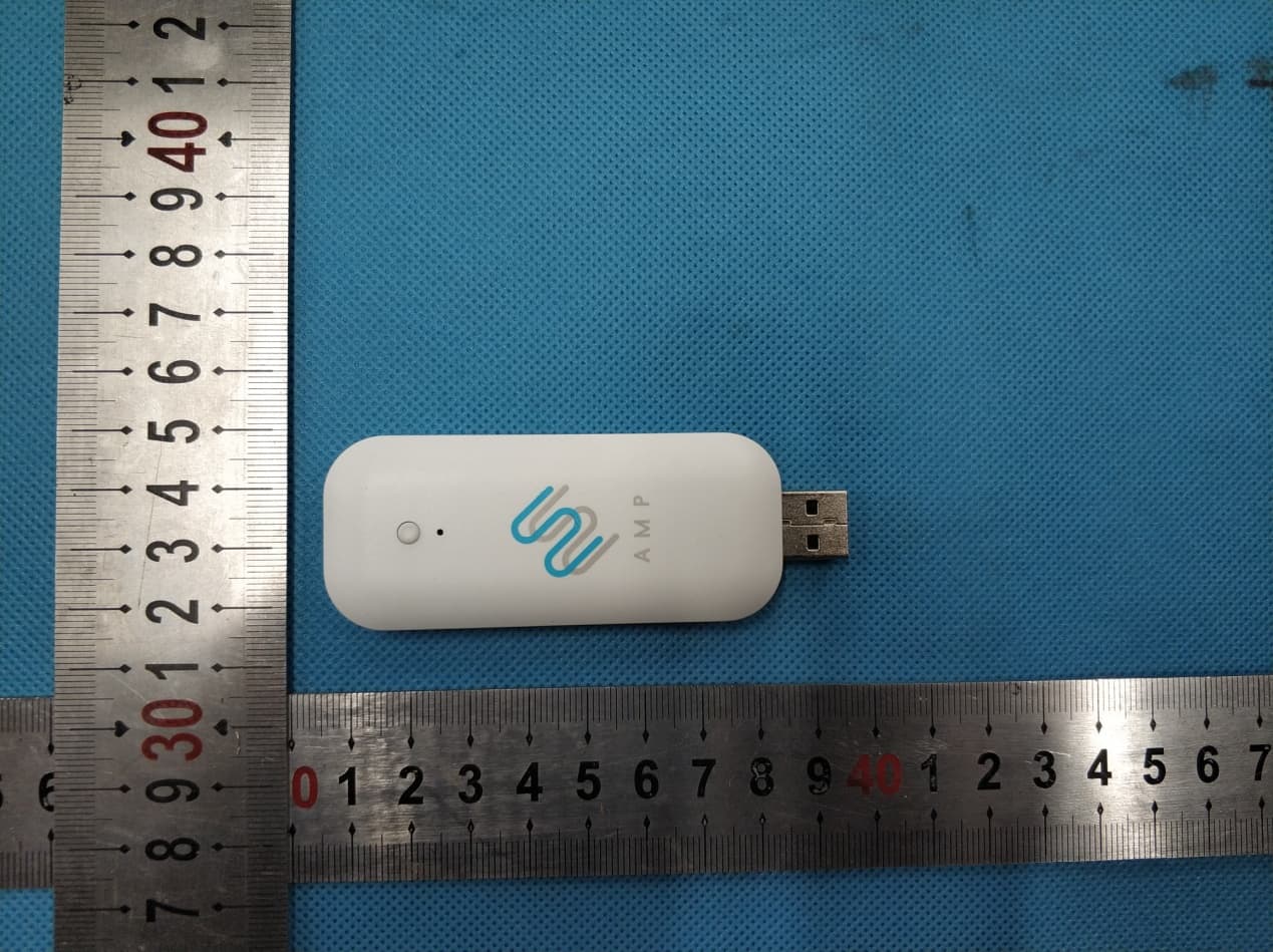
Click to zoom
Application Details
- Equipment Class
- DSR - Part 15 Remote Control/Security Device Transceiver
- Date of Grant
- May 25, 2020
- Application Purpose
- Original Equipment
- Date of Application
- May 25, 2020
- Equipment Note
- AMP Bridge
- Frequency Range
- 433.92000000 - 433.92000000
- Company
- Turnils North America
- Country
- United States
Documents & Files
Document Text
Text extracted from the exhibit documents filed with the FCC. Open a document above to read the original.
Users Manual
U.S. Radio Frequency FCC Compliance This device complies with Part 15 of the FCC Rules. Operation is subject to the following two conditions: (1) This device may not cause harmful interference, and (2) This device must accept any interference received, including interference that may cause undesired operation. This equipment has been tested and found to comply with the limits for a Class B digital device, pursuant to Part 15 of the FCC Rules. These limits are designed to provide reasonable protection against harmful interference in a residential installation. This equipment generates, uses, and can radiate radio frequency energy and, if not installed and used in accordance with the instructions, may cause harmful interference to radio communications. However, there is no guarantee that interference will not occur in a particular installation. If this equipment does cause harmful interference to radio or television reception, which can be determined by turning the equipment off and on, the user is encouraged to try to correct the interference by one or more of the following measures: • Reorient or relocate the receiving antenna. • Increase the separation between the equipment and receiver. • Connect the equipment into an outlet on a circuit different from that to which the receiver is connected. • Consult the dealer or an experienced radio/TV technician for help. Any Changes or modifications not expressly approved by the party responsible for compliance could void the user’s authority to operate the equipment. ISED RSS Warning: This device complies with Innovation, Science and Economic Development Canada licence- exempt RSS standard(s). Operation is subject to the following two conditions: (1) this device may not cause interference, and (2) this device must accept any interference, including interference that may cause undesired operation of the device. Le présent appareil est conforme aux CNR d’ISED applicables aux appareils radio exempts de licence. L’exploitation est autorisée aux deux conditions suivantes: (1) l’appareil ne doit pas produire de brouillage, et (2) l’utilisateur de l’appareil doit accepter tout brouillage radioélectrique subi, même si le brouillage est susceptible d’en compromettre le fonctionnement. FCC SAR Warning: RF Exposure Information (SAR): The SAR limit of USA (FCC)is 1.6W/Kg averaged over one gram of tissue. Product Type: AMP Bridge (FCC ID: 2AU29AMPRFWIFIUSB) has also been tested against this SAR limit. The device was tested for typical body-worn operations to keep the AMP Bridge at least 5mm from the body. When worn on body must be correct back clip for this product, use of non-approved accessories may result in exposure levels which exceed the uncontrolled environmental RF exposure limits. ISED SAR Warning: The SAR limit of IC is 1.6W/Kg averaged over one gram of tissue. Product Type: AMP Bridge, model number: AMP USB Bridge Wifi and RF (IC: 25624-AMPRFWIFI) has also been tested against this SAR limit. The device was tested for typical body-worn operations to keep the AMP Bridge at least 5mm from the body. When worn on body must be correct back clip for this product, use of non-approved accessories may result in exposure levels which exceed the uncontrolled environmental RF exposure limits. Le SAR de IC est limité à 1.6w / kg, avec une moyenne par gramme. Produits Type: AMP Bridge, type: AMP USB Bridge Wifi and RF (IC: 25624-AMPRFWIFI) a également été testé pour la limite SAR. Ce dispositif est utilisé pour tester des opérations d ‘usure corporelle typiques et des opérations en direction du Haut de physique, de manière à maintenir une distance d’ au moins 5mm entre le AMP Bridge et le visage. Osure.` Quick Start Guide for AMP ™ USB Bridge Product Certification AMP ™ USB Bridge allows the user to link their motorized Shades, Blinds, and Draperies into a Wi-Fi network, enabling control via smart APP and interaction with other IoT products. Step 1 Download APP Please scan the QR code below. Step 2 Please scan the QR code below to learn more about linking the AMP ™ USB Bridge with your home Wi-Fi router, setting up the AMP ™ APP, and establishing a connection with other IoT applications. Quick Start Guide for AMP ™ USB Bridge Product Certification AMP ™ USB Bridge allows the user to link their motorized Shades, Blinds, and Draperies into a Wi-Fi network, enabling control via smart APP and interaction with other IoT products. Step 1 Download APP Please scan the QR code below. Step 2 Please scan the QR code below to learn more about linking the AMP ™ USB Bridge with your home Wi-Fi router, setting up the AMP ™ APP, and establishing a connection with other IoT applications. Quick Start Guide for AMP ™ USB Bridge Product Certification AMP ™ USB Bridge allows the user to link their motorized Shades, Blinds, and Draperies into a Wi-Fi network, enabling control via smart APP and interaction with other IoT products. Step 1 Download APP Please scan the QR code below. Step 2 Please scan the QR code below to learn more about linking the AMP ™ USB Bridge with your home Wi-Fi router, setting up the AMP ™ APP, and establishing a connection with other IoT applications. Quick Start Guide for AMP ™ USB Bridge Product Certification AMP ™ USB Bridge allows the user to link their motorized Shades, Blinds, and Draperies into a Wi-Fi network, enabling control via smart APP and interaction with other IoT products. Step 1 Download APP Please scan the QR code below. Step 2 Please scan the QR code below to learn more about linking the AMP ™ USB Bridge with your home Wi-Fi router, setting up the AMP ™ APP, and establishing a connection with other IoT applications. AMP ™ Bridge Quick Start Guide DeclarationsStep 1 Step 2 AMP USB Bridge allows the user to link their motorized Shades, Blinds, and Draperies into a Wi-Fi network enabling control via smart APP and interaction with other IoT products. Please scan the QR Code below to download the app. Please scan the QR Code below to learn more …
Text truncated - open the document above for the full version.
Cover Letter(s)
QA-FR-170-B Company: Turnils North America Add: 1 750 Satellite Blvd, Suite 100, Buford, Georgia, 30518 United States Tel: 770-995-2222 Fax: 770-995-2210 FCC Authorization Date: 2020-03-02 FE DERAL COMMUNICATIONS COMMISSION Authorization and Evaluation Division 7435 Oakland Mills Road Columbia, MD 21046 Subject: Agent Authorization To whom it may concern: We, Turnils North America, the undersigned, Hereby authorizes Bay Area Compliance Laboratories Corporation to act on its behalf in all matters relating to application for Equipment authorization, including the signing of all documents relating to these matters. All acts carried out by Bay Area Compliance Laboratories Corp. on our behalf shall have the same effect as our own action. We, the undersigned, hereby certify that we are not subject to a denial of federal benefits, that includes FCC benefits, pursuant to Section 5301 of the Anti-Drug Abuse Act of 1988, 21 U.S.C. 862. This authorization is valid until further written notice from the applicant. Sincerely Yours, Signature: Typed or Printed Name: Phoenix Lin Title: Project Manager
Cover Letter(s)
Company: Turnils North America Add: 1750 Satellite Blvd, Suite 100, Buford, Georgia, 30518 United States Tel: 770-995-2222 Fax: 770-995-2210 E-mail: [email protected] FCC Confidential Authorization Date: 2020-03-02 FEDERAL COMMUNICATIONS COMMISSIONS Authorization and Evaluation Division 7435 Oakland Mills Road Columbia, MD 21046 Subject: Confidentiality Request regarding application for certification of FCC ID: 2AU29AMPRFWIFIUSB To: whom it may concern, In accordance with Sections 0.457 and 0.459 of the Commission’s Rules, Turnils North America hereby requests long-term confidential treatment of information accompanyi ng t his application as outlined below: Block Diagram Schematics Operation Description The above materials contain proprietary and confidential information not customarily released to the public. The public disclosure of these materials provides unjustified benefits to its competitors in the market. Sincerely Yours, Signature: Typed or Printed Name: Phoenix Lin Title: Project Manager
External Photos
EXHIBIT A - EUT EXTERNAL PHOTOGRAPHS
Internal Photos
EXHIBIT B- EUT INTERNAL PHOTOGRAPHS 2.4G Wi-Fi Antenna SRD Antenna
Test Report
Note: This test report is prepared for the customer shown above and for the device described herein. It may not be duplicated or used in part without prior written consent from Bay Area Compliance Laboratories Corp. This report is valid only with a valid digital signature. The digital signature may be available only under the Adobe software above version 7.0. FCC PART 15.231 TEST REPORT For Turnils North America 1750 Satellite Blvd, Suite 100, Buford, Georgia, 30518 United States FCC ID: 2AU29AMPRFWIFIUSB Report Type: Original Report Product Type: AMP Bridge Test Engineer: Nolan Xu Report Number: RSHA200302003-00B Report Date: 2020-04-26 Reviewed By: Oscar Ye EMC Manager Prepared By: Bay Area Compliance Laboratories Corp. (Kunshan) No.248 Chenghu Road, Kunshan, Jiangsu province, China Tel: +86-0512-86175000 Fax: +86-0512-88934268 www.baclcorp.com.cn Bay Area Compliance Laboratories Corp. (Kunshan) Report No.: RSHA200302003-00B FCC Part 15.231 Page 2 of 23 TABLE OF CONTENTS GENERAL INFORMATION ....................................................................................................................................... 3 PRODUCT DESCRIPTION FOR EQUIPMENT UNDER TEST (EUT) ..................................................................................... 3 OBJECTIVE ................................................................................................................................................................... 3 TEST METHODOLOGY .................................................................................................................................................. 3 MEASUREMENT UNCERTAINTY .................................................................................................................................... 4 TEST FACILITY ............................................................................................................................................................. 4 SYSTEM TEST CONFIGURATION .......................................................................................................................... 5 JUSTIFICATION ............................................................................................................................................................. 5 EUT EXERCISE SOFTWARE .......................................................................................................................................... 5 EQUIPMENT MODIFICATIONS ....................................................................................................................................... 5 SUPPORT EQUIPMENT LIST AND DETAILS .................................................................................................................... 5 EXTERNAL I/O CABLE .................................................................................................................................................. 5 BLOCK DIAGRAM OF TEST SETUP ................................................................................................................................ 6 SUMMARY OF TEST RESULTS ............................................................................................................................... 8 TEST EQUIPMENT LIST ........................................................................................................................................... 9 FCC§15.203 - ANTENNA REQUIREMENT ............................................................................................................ 10 APPLICABLE STANDARD ............................................................................................................................................ 10 ANTENNA CONNECTED CONSTRUCTION .................................................................................................................... 10 FCC §15.207 (A) - AC LINE CONDUCTED EMISSIONS ..................................................................................... 11 APPLICABLE STANDARD ............................................................................................................................................ 11 EUT SETUP ................................................................................................................................................................ 11 EMI TEST RECEIVER SETUP ....................................................................................................................................... 11 TEST PROCEDURE ...................................................................................................................................................... 11 FACTOR & OVER LIMIT CALCULATION ...................................................................................................................... 12 TEST RESULTS SUMMARY .......................................................................................................................................... 12 TEST DATA ................................................................................................................................................................ 12 FCC §15.205, §15.209, §15.231 (B) - RADIATED EMISSIONS ............................................................................. 15 APPLICABLE STANDARD ............................................................................................................................................ 15 EUT SETUP ................................................................................................................................................................ 16 EMI TEST RECEIVER SETUP ....................................................................................................................................... 17 TEST PROCEDURE ...................................................................................................................................................... 17 CORRECTED AMPLITUDE & MARGIN CA…
Text truncated - open the document above for the full version.
Test Setup Photos
EXHIBIT C- TEST SETUP PHOTOGRAPHS Conducted Emissions (Front View) Conducted Emissions (Side View) Radiated Emissions (Below 1GHz) Radiated Emissions (Above 1GHz)
Contact Information
Applicant
Phoenix Lin(Senior Project Manager)
Test Firm
Bay Area Compliance Laboratories Corp. (Kunshan)Mr. John Chan
[email protected]+86 0512 86175000
Technical Specifications
| # | Rule Parts | Frequency Range | Power Output |
|---|---|---|---|
| 1 | 15.231 | 433.92 MHz - 433.92 MHz | - |
Other Applications from Turnils North America
2AU29AMPSNHUBV1
Jan 18, 2024Smart Hub
Equipment Class
DSC - Part 15 Security/Remote Control Transmitter2AU29AMPSNHUBFV1
Jan 18, 2024Smith & Noble Smart Hub
Equipment Class
DSC - Part 15 Security/Remote Control Transmitter2AU29AMPRFWIFIUSBV3
Jan 16, 2024AMP Bridge
Equipment Class
DSC - Part 15 Security/Remote Control Transmitter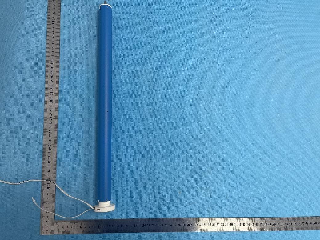
2AU29AMP28BDCV2
Dec 16, 2023DC Tubular Motor with built-in RF control
Equipment Class
DSR - Part 15 Remote Control/Security Device Transceiver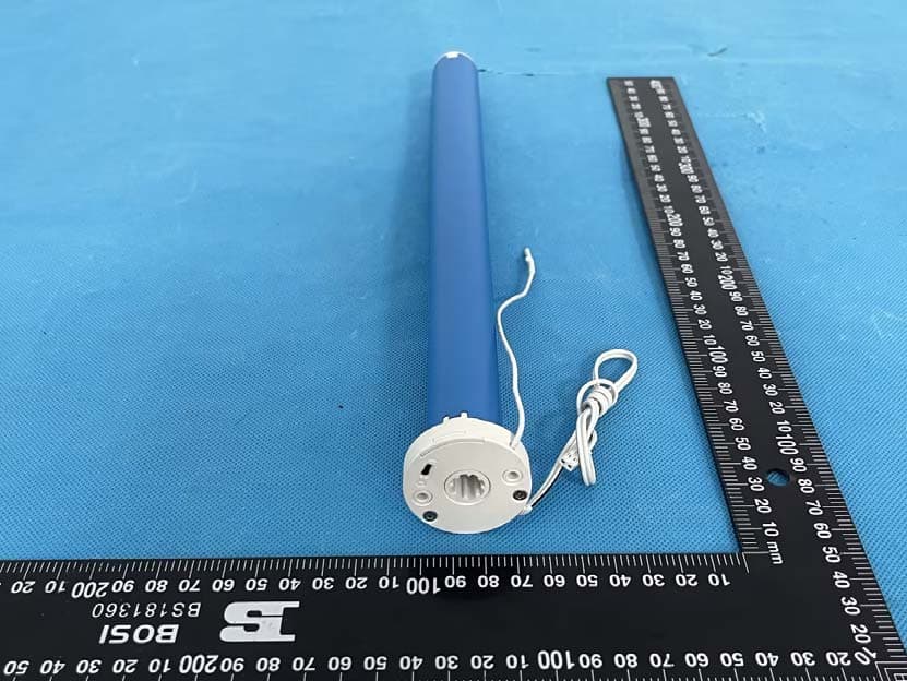
2AU29AMP25BDCV3
Jul 09, 2023DC Tubular Motor for Narrow Shades
Equipment Class
DSC - Part 15 Security/Remote Control Transmitter