2AUA9-RQZY002AC2100 Dual Band WiFi Repeater
Shenzhen Renqing Excellent Technology Co., Ltd.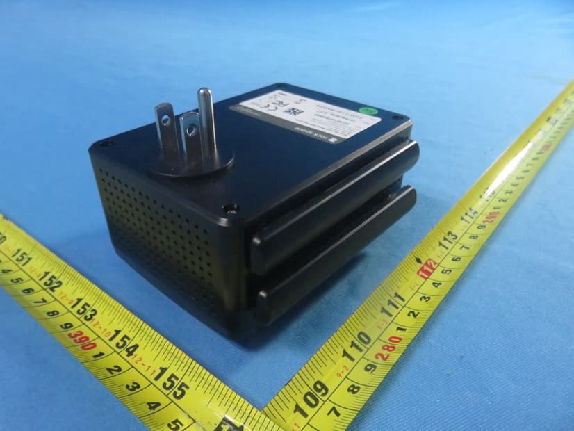
Click to zoom
Application Details
- Equipment Class
- NII - Unlicensed National Information Infrastructure TX
- Date of Grant
- Jul 27, 2020
- Application Purpose
- Original Equipment
- Date of Application
- Jul 27, 2020
- Equipment Note
- AC2100 Dual Band WiFi Repeater
- Frequency Range
- 5745.00000000 - 5825.00000000
- Country
- China
Documents & Files
Document Text
Text extracted from the exhibit documents filed with the FCC. Open a document above to read the original.
Users Manual
LED Descriptions O No connection. Solid red Poor connection. Solid blueBest connection WPS LED On WiFi security is enabled (WPA or WPA2). BlinkingA WPS connection is in progress. O WiFi security is not enabled. Power LED Solid on The extender is powered on. The extender is powered o . O The extender is booting.Blinking Signal LED This LED indicates the connection between the extender and the router. AC2100 Dual Band WiFi Repeater Model: RSD0617 Technical Support: Phone: 1-833-816-6558 (EST: 9:00-17:00 / PDT: 06:00-14:00 Monday to Friday) Email: [email protected] To restore the WiFi range extender to the original factory settings: Plug the extender into a power outlet (the reset pinhole is on the bottom of the extender), using a paperclip, press and hold the reset pinhole for 8 seconds, and then let go. The AC2100 WiFi range extender will then reboot and be at factory default settings. Description Button RST Quick Start Guide www.rockspace.hk WiFi router Antennas upward and vertical to the ground Blue: successfully connected Red: connection failed RSD0617 Signal Method 1: Connect to an Existing WiFi Network with Web Browser Setup 1 Place the Extender and Apply Power Place your extender in the same room as your WiFi router. Plug the extender into an electrical outlet. Wait for the Power LED to light blue. 3. Select a WiFi network to extend. 4. In the password eld, type the password for the existing WiFi network you previously selected. Select a WiFi network you want to extend... My_home_wi RescanSwitch Mode Your existing WiFi network Enter the password of “My_home_wi ” My_home_wi Password of the extended network is same as your existing WiFi network. The extended WiFi network SSID BackExtend Password (5-32 characters) Con rm NextNot Now http://re.rockspace.local 2 Extend Your WiFi Network 1. Use a WiFi network manager on your client device, such as a computer or WiFi device, to nd and connect to the "rockspace_EXT " (SSID) WiFi network. Ensure that the Mobile Data is disabled. WLAN rockspace_EXT 2. After the connection with your client device is established, the setup page will automatically pop up. If the setup page doesn't pop up automatically, you will need to launch web browser and enter http://re.rockspace.local or 192.168.0.254 to get started. In the Password eld, type the password that you wish to use to log into the management interface. Note: The password you entered in this step is NOT the password for your extended network, it is the password for the extender's management interface. The SSID of the extended network can be modi ed, otherwise it will remain the same as that of the existing network you chose to extend. Wait for the page to display a list of WiFi networks, connect your client device to the new extender WiFi network. Note: The password for the extended network you entered in step 4 should be the same as the password for your existing WiFi network. 3 Relocate the WiFi Range Extender 1. Unplug the extender and move it to a new location about halfway between your router and the area with a poor WiFi signal. The location that you choose must be within the range of your existing WiFi router network. 3. Use a WiFi network manager on your client device, such as a computer or WiFi device, to nd and connect to the extended WiFi network you've set up in the previous step. Note: The password for the extended network is the same as the password for your existing WiFi network. 2. Plug the extender into an electrical outlet and wait for the Signal LED to light blue. If not, plug the extender into an outlet closer to the router and try again. PWR Method 2: Connect to an Existing WiFi Network with WPS You can use Method 2 if your router has a WPS button (possible icons of a WPS button: , , or ). Otherwise, use Method 1. 1 Place the Extender and Apply Power Place your extender in the same room as your WiFi router. Plug the extender into an electrical outlet. Wait for the Power LED to light blue. PWR 2 Extend Your WiFi Network 1. Press the WPS button on your router. Within two minutes, press the WPS button on the extender. 2. Wait until the Signal LED on the repeater turns solid blue. If the Signal LED does not turn solid blue, try Method 1. Press A8: Q8: The indicator shows red or no light (weak signal or filed connecting)? How to con rm a successful extension? you can check the Network Name (SSID)if is still factory setting name ( "rockspace_EXT"), then it means a failed signal extension Log in to the extender website to check the extender state is extended signal or not. If you are sure that the extension is successful, you can keep the antenna upward and parallel with the antenna of the router; If not, please replace its angle. You can put the repeater and router closer, and observe if the indicator gets solid blue. A9: Q9: No internet access after extension? Con rm whether the extension is successful. (Judge by indicator and management interface) Disconnecting the device without internet access, and connect again to see if it is available. Check the router signal strength, if the router signal strength is too low, the extender has hardly extended the signal and doesn't have internet access.(We recommend the repeater should be placed somewhere between 40%-50% of the signal strength.) When the signal of the repeater is connected, see if its SSID is assigned by router. Reset the repeater and try others WIFI signal. FAQ Q3: Why is it useless to press the RST button? A3: Please con rm long press the RST button for 8 seconds with power on. A4: The router may be encrypted with WEP or WPA/WPA (Enterprise) algorithm. Change the encryption type of the router to WPA-PSK or WPA2-PSK, and try scanning again. Q4: The repeater cannot find the WiFi network of my router/modem. What should I do? Q2: How to reset the repeater? A2: When the PWR LED of the repeater is solid on, press the RESET button on the repeater with power on using a paper clip, and release. After the PWR LED turns …
Text truncated - open the document above for the full version.
External Photos
Report No.: 2006C111 Page 1 of 8 ATTACHMENT PHOTOGRAPHS OF EUT Report No.: 2006C111 Page 2 of 8 Report No.: 2006C111 Page 3 of 8
ID Label/Location Info
RSD0617 FCC ID:2AUA9-RQZY002 re.rockspace.local 57.7*34.7mm R=2.15mm 80g铜版纸 背油胶 单色印刷 -0.3mm 过哑膜 50PCS A21V1.0-ROC01铜版贴 A21V1.0-ROC01 2020/03/09 01 www.rockspace.hk
Internal Photos
Report No.: 2006C111 Page 1 of 8 ATTACHMENT PHOTOGRAPHS OF EUT Report No.: 2006C111 Page 2 of 8 Report No.: 2006C111 Page 3 of 8 Report No.: 2006C111 Page 4 of 8 5G Ant. 1 5G Ant. 2 5G Ant. 3+2.4G Ant. 1 5G Ant. 4+2.4G Ant. 2 Report No.: 2006C111 Page 5 of 8 Report No.: 2006C111 Page 6 of 8 Report No.: 2006C111 Page 7 of 8 Report No.: 2006C111 Page 8 of 8
RF Exposure Info
Report No.: BTL-FCCP-3-2006C111 Page 1 of 5 FCC RF EXPOSURE REPORT FCC ID: 2AUA9-RQZY002 Project No. : 2006C111 Equipment : AC2100 Dual Band WiFi Repeater Brand Name : ROCK, rock space Test Model : RSD0617 Series Model : N/A Applicant : Shenzhen Renqing Excellent Technology Co., Ltd. Address : 104, No.15, Longfu Industrial Zone, Tongsheng Community, Dalang Street, Longhua District, Shenzhen, Guangdong, China Manufacturer : Shenzhen Renqing Excellent Technology Co., Ltd. Address : 104, No.15, Longfu Industrial Zone, Tongsheng Community, Dalang Street, Longhua District, Shenzhen, Guangdong, China Date of Receipt : Jun. 22, 2020 Date of Test : Jun. 23, 2020 ~ Jul. 15, 2020 Issued Date : Jul. 23, 2020 Report Version : R00 Test Sample : Engineering Sample No.: DG2020061981 Standard(s) : FCC Guidelines for Human Exposure IEEE C95.1 & FCC Part 2.1091 FCC Title 47 Part 2.1091, OET Bulletin 65 Supplement C The above equipment has been tested and found compliance with the requirement of the relative standards by BTL Inc. Prepared by : Chay Cai Approved by : Ethan Ma Add: No.3, Jinshagang 1st Road, Shixia, Dalang Town,Dongguan, Guangdong, China. Te l : +86-769-8318-3000 Web: www.newbtl.com Report No.: BTL-FCCP-3-2006C111 Page 2 of 5 REPORT ISSUED HISTORY Report Version Description Issued Date R00 Original Issue Jul. 23, 2020 Report No.: BTL-FCCP-3-2006C111 Page 3 of 5 1. TEST FACILITY The test facilities used to collect the test data in this report is at the location of No.3,Jinshagang 1st Road, Shixia, Dalang Town, Dongguan, Guangdong, China. BTL's Test Firm Registration Number for FCC: 357015 BTL's Designation Number for FCC: CN1240 2. MPE CALCULATION METHOD Calculation Method of RF Safety Distance: where: S = power density P = power input to the antenna G = power gain of the antenna in the direction of interest relative to an isotropic radiator R = distance to the center of radiation of the antenna Table for Filed Antenna: For WLAN 2.4G: Ant. Brand Model Name Antenna Type Connector Gain (dBi) 1 N/A N/A Dipole N/A 3.4 2 N/A N/A Dipole N/A 3.5 Note: 1) This EUT supports CDD, and antenna gains are not equal, so Directional gain=10log [(10 G1/20 +10 G2/20 +...10 GN/20 ) 2 /N]dBi=6.46. So the output power limit is 30-(6.46-6)=29.54, the power spectral density limit is 8-(6.46-6)=7.54. 2) Beamforming Gain: 3 dB. Then the Directional Gain=3+3.5=6.5 dB. So the output power limit is 30-(6.5-6)=29.50. Table for Antenna Configuration: For Non Beamforming Operating Mode TX Mode 1TX 2TX 802.11b V (Ant. 1) - 802.11g V (Ant. 1) - IEEE 802.11n (HT20) - V (Ant. 1 + Ant. 2) IEEE 802.11n (HT40) - V (Ant. 1 + Ant. 2 ) For Beamforming Operating Mode TX Mode 2TX IEEE 802.11n (HT20) V (Ant. 1 + Ant. 2) IEEE 802.11n (HT40) V (Ant. 1 + Ant. 2) Report No.: BTL-FCCP-3-2006C111 Page 4 of 5 For WLAN 5G: Ant. Brand Model Name Antenna Type Connector Gain (dBi) Note 1 N/A N/A Dipole N/A 2.7 UNII-1 2 N/A N/A Dipole N/A 3.3 UNII-1 3 N/A N/A Dipole N/A 3.7 UNII-1 4 N/A N/A Dipole N/A 3.7 UNII-1 1 N/A N/A Dipole N/A 3.6 UNII-3 2 N/A N/A Dipole N/A 3.7 UNII-3 3 N/A N/A Dipole N/A 3.8 UNII-3 4 N/A N/A Dipole N/A 3.9 UNII-3 Note: 1) This EUT supports CDD, and all antenna gains are not equal. So, the Directional gain=10log[(10 G1/20 +10 G2/20 +...10 GN/20 ) 2 /N]dBi. a) For UNII-1, the Directional gain = 10log[(10 2.7/20 +10 3.3/20 +10 3.7/20 10 3.7/20 ) 2 /4]=9.38. So the output power limit is 30-(9.38-6)=26.62, the power spectral density limit is 17-(9.38-6)=13.62. b) For UNII-3, the Directional gain=10log[(10 3.6/20 +10 3.7/20 +10 3.8/20 10 3.9/20 ) 2 /4]=9.77. So the output power limit is 30-(9.77-6)=26.23, the power spectral density limit is 30-(9.77-6)=26.23. 2) Beamforming Gain: 6dB. a) For UNII-1: The Directional gain=6+3.7=9.70dB. So the output power limit is 30-(9.70-6)=26.30. b) For UNII-3: The Directional gain=6+3.9=9.90dB. So the output power limit is 30-(9.90-6)=26.10. Table for Antenna Configuration: For Non Beamforming: Operating Mode TX Mode 1TX 4TX IEEE 802.11a V (Ant. 1) - IEEE 802.11n (HT20) - V (Ant. 1 + Ant. 2 + Ant. 3 + Ant. 4) IEEE 802.11n (HT40) - V (Ant. 1 + Ant. 2 + Ant. 3 + Ant. 4) IEEE 802.11ac(VHT20) - V (Ant. 1 + Ant. 2 + Ant. 3 + Ant. 4 ) IEEE 802.11ac(VHT40) - V (Ant. 1 + Ant. 2 + Ant. 3 + Ant. 4) IEEE 802.11ac(VHT80) - V (Ant. 1 + Ant. 2 + Ant. 3 + Ant. 4) For Beamforming: Operating Mode TX Mode 4TX IEEE 802.11n (HT20) V (Ant. 1 + Ant. 2 + Ant. 3 + Ant. 4) IEEE 802.11n (HT40) V (Ant. 1 + Ant. 2 + Ant. 3 + Ant. 4) IEEE 802.11ac(VHT20) V (Ant. 1 + Ant. 2 + Ant. 3 + Ant. 4) IEEE 802.11ac(VHT40) V (Ant. 1 + Ant. 2 + Ant. 3 + Ant. 4) IEEE 802.11ac(VHT80) V (Ant. 1 + Ant. 2 + Ant. 3 + Ant. 4) Report No.: BTL-FCCP-3-2006C111 Page 5 of 5 3. TEST RESULTS For 2.4GHz Non Beamforming: Directional Gain (dBi) Directional Gain (numeric) Max. Average Output Power (dBm) Max. Average Output Power (mW) Power Density (S) (mW/cm 2 ) Limit of Power Density (S) (mW/cm 2 ) Test Result 6.46 4.4259 21.64 145.8814 0.12851 1 Complies For 2.4GHz Beamforming: Directional Gain (dBi) Directional Gain (numeric) Max. Average Output Power (dBm) Max. Average Output Power (mW) Power Density (S) (mW/cm 2 ) Limit of Power Density (S) (mW/cm 2 ) Test Result 6.50 4.4668 21.47 140.2814 0.12472 1 Complies For 5GHz UNII-1 Non Beamforming: Directional Gain (dBi) Directional Gain (numeric) Max. Output Power (dBm) Max. Output Power (mW) Power Density (S) (mW/cm 2 ) Limit of Power Density (S) (mW/cm 2 ) Test Result 9.38 8.6696 23.73 236.0478 0.40733 1 Complies For 5GHz UNII-1 Beamforming: Directional Gain (dBi) Directional Gain (numeric) Max. Output Power (dBm) Max. Output Power (mW) Power Density (S) (mW/cm 2 ) Limit of Power Density (S) (mW/cm 2 ) Test Result 9.70 9.3325 23.4 218.7762 0.40640 1 Complies For 5GHz UNII-3 Non Beamforming: Directional Gain (dBi) Directional Gain (numeric) Max. Output Power (dBm) Max. Output Power (mW) Power Density (S) (mW/cm 2 ) Limit of Power Density (S) (mW/cm 2 ) Test Result 9.77 9.4842 26.21 417.8304 0.78877 1 C…
Text truncated - open the document above for the full version.
Test Report
Report No.: BTL-FCCP-2-2006C111 Page 1 of 176 FCC Radio Test Report FCC ID: 2AUA9-RQZY002 This report concerns: Original Grant Project No. : 2006C111 Equipment : AC2100 Dual Band WiFi Repeater Brand Name : ROCK, rock space Test Model : RSD0617 Series Model : N/A Applicant : Shenzhen Renqing Excellent Technology Co., Ltd. Address : 104, No.15, Longfu Industrial Zone, Tongsheng Community, Dalang Street, Longhua District, Shenzhen, Guangdong, China Manufacturer : Shenzhen Renqing Excellent Technology Co., Ltd. Address : 104, No.15, Longfu Industrial Zone, Tongsheng Community, Dalang Street, Longhua District, Shenzhen, Guangdong, China Date of Receipt : Jun. 22, 2020 Date of Test : Jun. 23, 2020 ~ Jul. 15, 2020 Issued Date : Jul. 23, 2020 Report Version : R00 Test Sample : Engineering Sample No.: DG2020061981 for conducted, DG2020061982 for radiated. Standard(s) : FCC Part15, Subpart E(15.407) ANSI C63.10-2013 FCC KDB 789033 D02 General UNII Test Procedures New Rules v02r01 FCC KDB 662911 D01 Multiple Transmitter Output v02r01 The above equipment has been tested and found compliance with the requirement of the relative standards by BTL Inc. Prepared by : Chay Cai Approved by : Ethan Ma Add: No.3, Jinshagang 1st Road, Shixia, Dalang Town,Dongguan, Guangdong, China. Te l : +86-769-8318-3000 Web: www.newbtl.com Report No.: BTL-FCCP-2-2006C111 Page 2 of 176 Declaration BTL represents to the client that testing is done in accordance with standard procedures as applicable and that test instruments used has been calibrated with standards traceable to international standard(s) and/or national standard(s). BTL's reports apply only to the specific samples tested under conditions. It is manufacture’s responsibility to ensure that additional production units of this model are manufactured with the identical electrical and mechanical components. BTL shall have no liability for any declarations, inferences or generalizations drawn by the client or others from BTL issued reports. The report must not be used by the client to claim product certification, approval, or endorsement by NVLAP, NIST, A2LA, or any agency of the U.S. Government. This report is the confidential property of the client. As a mutual protection to the clients, the public and ourselves, the test report shall not be reproduced, except in full, without our written approval. BTL’s laboratory quality assurance procedures are in compliance with the ISO/IEC 17025 requirements, and accredited by the conformity assessment authorities listed in this test report. BTL is not responsible for the sampling stage, so the results only apply to the sample as received. The information, data and test plan are provided by manufacturer which may affect the validity of results, so it is manufacturer’s responsibility to ensure that the apparatus meets the essential requirements of applied standards and in all the possible configurations as representative of its intended use. Limitation For the use of the authority's logo is limited unless the Test Standard(s)/Scope(s)/Item(s) mentioned in this test report is (are) included in the conformity assessment authorities acceptance respective. Please note that the measurement uncertainty is provided for informational purpose only and are not use in determining the Pass/Fail results. Report No.: BTL-FCCP-2-2006C111 Page 3 of 176 Table of Contents Page REPORT ISSUED HISTORY 6 1 . SUMMARY OF TEST RESULTS 7 1.1 TEST FACILITY 8 1.2 MEASUREMENT UNCERTAINTY 8 1.3 TEST ENVIRONMENT CONDITIONS 9 2 . GENERAL INFORMATION 10 2.1 GENERAL DESCRIPTION OF EUT 10 2.2 TEST MODES 13 2.3 PARAMETERS OF TEST SOFTWARE 16 2.4 DUTY CYCLE 18 2.5 BLOCK DIAGRAM SHOWING THE CONFIGURATION OF SYSTEM TESTED 20 2.6 SUPPORT UNITS 20 3 . AC POWER LINE CONDUCTED EMISSIONS TEST 21 3.1 LIMIT 21 3.2 TEST PROCEDURE 21 3.3 DEVIATION FROM TEST STANDARD 21 3.4 TEST SETUP 22 3.5 EUT OPERATION CONDITIONS 22 3.6 TEST RESULTS 22 4 . RADIATED EMISSIONS TEST 23 4.1 LIMIT 23 4.2 TEST PROCEDURE 24 4.3 DEVIATION FROM TEST STANDARD 24 4.4 TEST SETUP 25 4.5 EUT OPERATION CONDITIONS 26 4.6 TEST RESULTS - 9 KHZ to 30 MHZ 26 4.7 TEST RESULTS - 30 MHz TO 1000 MHz 26 4.8 TEST RESULTS - ABOVE 1000 MHz 26 5 . BANDWIDTH TEST 27 5.1 LIMIT 27 5.2 TEST PROCEDURE 27 5.3 DEVIATION FROM STANDARD 27 Report No.: BTL-FCCP-2-2006C111 Page 4 of 176 Table of Contents Page 5.4 TEST SETUP 28 5.5 EUT OPERATION CONDITIONS 28 5.6 TEST RESULTS 28 6 . MAXIMUM OUTPUT POWER TEST 29 6.1 LIMIT 29 6.2 TEST PROCEDURE 29 6.3 DEVIATION FROM STANDARD 29 6.4 TEST SETUP 29 6.5 EUT OPERATION CONDITIONS 29 6.6 TEST RESULTS 29 7 . POWER SPECTRAL DENSITY TEST 30 7.1 LIMIT 30 7.2 TEST PROCEDURE 30 7.3 DEVIATION FROM STANDARD 30 7.4 TEST SETUP 31 7.5 EUT OPERATION CONDITIONS 31 7.6 TEST RESULTS 31 8 . FREQUENCY STABILITY MEASUREMENT 32 8.1 LIMIT 32 8.2 TEST PROCEDURE 32 8.3 DEVIATION FROM STANDARD 32 8.4 TEST SETUP 32 8.5 EUT OPERATION CONDITIONS 32 8.6 TEST RESULTS 32 9 . MEASUREMENT INSTRUMENTS LIST 33 10 . EUT TEST PHOTOS 35 APPENDIX A - AC POWER LINE CONDUCTED EMISSIONS 39 APPENDIX B - RADIATED EMISSION - 9 KHZ TO 30 MHZ 44 APPENDIX C - RADIATED EMISSION - 30 MHZ TO 1 GHZ 49 APPENDIX D - RADIATED EMISSION - ABOVE 1000 MHZ 52 APPENDIX E - BANDWIDTH 127 APPENDIX F - MAXIMUM OUTPUT POWER 136 Report No.: BTL-FCCP-2-2006C111 Page 5 of 176 Table of Contents Page APPENDIX G - POWER SPECTRAL DENSITY 158 APPENDIX H - FREQUENCY STABILITY 174 Report No.: BTL-FCCP-2-2006C111 Page 6 of 176 REPORT ISSUED HISTORY Report Version Description Issued Date R00 Original Issue. Jul. 23, 2020 Report No.: BTL-FCCP-2-2006C111 Page 7 of 176 1. SUMMARY OF TEST RESULTS Test procedures according to the technical standard(s): FCC Part15, Subpart E(15.407) Standard(s) Section Test Item Test Result Judgment Remark 15.207 15.407(b) AC Power Line Conducted Emissions APPENDIX A PASS ------ 15.407(b) 15.205(a) 15.209(a) Radiated Emissions APPENDIX B APPENDIX C APPENDIX D PASS ------ 15.407(a) 15.407(e) Spectrum Bandwidth APPENDIX E PASS ------ 15.…
Text truncated - open the document above for the full version.
Test Report
Report No.: BTL-FCCP-2-2006C111 Page 135 of 176 Test Mode UNII-3_TX AC (VHT80) Mode Channel Frequency (MHz) 6 dB Bandwidth (MHz) 99 % Emission Bandwidth (MHz) 6 dB Bandwidth Min. Limit (kHz) Result 155 5775 73.00 86.40 500 Complies CH155 6 dB Bandwidth Report No.: BTL-FCCP-2-2006C111 Page 136 of 176 APPENDIX F - MAXIMUM OUTPUT POWER Report No.: BTL-FCCP-2-2006C111 Page 137 of 176 Non Beamforming Test Mode UNII-1_TX A Mode Channel Frequency (MHz) Output Power (dBm) Duty Factor Output Power + Duty Factor (dBm) Max. Limit (dBm) Max. Limit (W) Result 36 5180 17.13 0.44 17.57 30.00 1.00 Complies 40 5200 17.97 0.44 18.41 30.00 1.00 Complies 48 5240 18.46 0.44 18.90 30.00 1.00 Complies Test Mode UNII-3_TX A Mode Channel Frequency (MHz) Output Power (dBm) Duty Factor Output Power + Duty Factor (dBm) Max. Limit (dBm) Max. Limit (W) Result 149 5745 21.03 0.44 21.47 30.00 1.00 Complies 157 5785 21.13 0.44 21.57 30.00 1.00 Complies 165 5825 20.93 0.44 21.37 30.00 1.00 Complies Report No.: BTL-FCCP-2-2006C111 Page 138 of 176 Te st Mode UNII-1_TX N (HT20) Mode_Ant. 1 Channel Frequency (MHz) Output Power (dBm) Duty Factor Output Power + Duty Factor (dBm) Max. Limit (dBm) Max. Limit (W) Result 36 5180 15.98 0.62 16.60 30.00 1.00 Complies 40 5200 16.13 0.62 16.75 30.00 1.00 Complies 48 5240 15.79 0.62 16.41 30.00 1.00 Complies Test Mode UNII-1_TX N (HT20) Mode_Ant. 2 Channel Frequency (MHz) Output Power (dBm) Duty Factor Output Power + Duty Factor (dBm) Max. Limit (dBm) Max. Limit (W) Result 36 5180 14.26 0.62 14.88 30.00 1.00 Complies 40 5200 14.96 0.62 15.58 30.00 1.00 Complies 48 5240 13.88 0.62 14.50 30.00 1.00 Complies Test Mode UNII-1_TX N (HT20) Mode_Ant. 3 Channel Frequency (MHz) Output Power (dBm) Duty Factor Output Power + Duty Factor (dBm) Max. Limit (dBm) Max. Limit (W) Result 36 5180 16.01 0.62 16.63 30.00 1.00 Complies 40 5200 16.33 0.62 16.95 30.00 1.00 Complies 48 5240 15.84 0.62 16.46 30.00 1.00 Complies Test Mode UNII-1_TX N (HT20) Mode_Ant. 4 Channel Frequency (MHz) Output Power (dBm) Duty Factor Output Power + Duty Factor (dBm) Max. Limit (dBm) Max. Limit (W) Result 36 5180 13.36 0.62 13.98 30.00 1.00 Complies 40 5200 12.86 0.62 13.48 30.00 1.00 Complies 48 5240 13.14 0.62 13.76 30.00 1.00 Complies Test Mode UNII-1_TX N (HT20) Mode_Total Channel Frequency (MHz) Output Power (dBm) Max. Limit (dBm) Max. Limit (W) Result 36 5180 21.68 26.62 0.46 Complies 40 5200 21.91 26.62 0.46 Complies 48 5240 21.46 26.62 0.46 Complies Report No.: BTL-FCCP-2-2006C111 Page 139 of 176 Test Mode UNII-1_TX N (HT40) Mode_Ant. 1 Channel Frequency (MHz) Output Power (dBm) Duty Factor Output Power + Duty Factor (dBm) Max. Limit (dBm) Max. Limit (W) Result 38 5190 15.83 1.27 17.10 30.00 1.00 Complies 46 5230 17.76 1.27 19.03 30.00 1.00 Complies Test Mode UNII-1_TX N (HT40) Mode_Ant. 2 Channel Frequency (MHz) Output Power (dBm) Duty Factor Output Power + Duty Factor (dBm) Max. Limit (dBm) Max. Limit (W) Result 38 5190 12.22 1.27 13.49 30.00 1.00 Complies 46 5230 15.46 1.27 16.73 30.00 1.00 Complies Test Mode UNII-1_TX N (HT40) Mode_Ant. 3 Channel Frequency (MHz) Output Power (dBm) Duty Factor Output Power + Duty Factor (dBm) Max. Limit (dBm) Max. Limit (W) Result 38 5190 14.93 1.27 16.20 30.00 1.00 Complies 46 5230 16.83 1.27 18.10 30.00 1.00 Complies Test Mode UNII-1_TX N (HT40) Mode_Ant. 4 Channel Frequency (MHz) Output Power (dBm) Duty Factor Output Power + Duty Factor (dBm) Max. Limit (dBm) Max. Limit (W) Result 38 5190 12.21 1.27 13.48 30.00 1.00 Complies 46 5230 14.18 1.27 15.45 30.00 1.00 Complies Test Mode UNII-1_TX N (HT40) Mode_Total Channel Frequency (MHz) Output Power (dBm) Max. Limit (dBm) Max. Limit (W) Result 38 5190 21.38 26.62 0.46 Complies 46 5230 23.55 26.62 0.46 Complies Report No.: BTL-FCCP-2-2006C111 Page 140 of 176 Test Mode UNII-3_TX N (HT20) Mode_Ant. 1 Channel Frequency (MHz) Output Power (dBm) Duty Factor Output Power + Duty Factor (dBm) Max. Limit (dBm) Max. Limit (W) Result 149 5745 18.06 0.62 18.68 30.00 1.00 Complies 157 5785 18.47 0.62 19.09 30.00 1.00 Complies 165 5825 18.29 0.62 18.91 30.00 1.00 Complies Test Mode UNII-3_TX N (HT20) Mode_Ant. 2 Channel Frequency (MHz) Output Power (dBm) Duty Factor Output Power + Duty Factor (dBm) Max. Limit (dBm) Max. Limit (W) Result 149 5745 14.82 0.62 15.44 30.00 1.00 Complies 157 5785 14.52 0.62 15.14 30.00 1.00 Complies 165 5825 15.91 0.62 16.53 30.00 1.00 Complies Test Mode UNII-3_TX N (HT20) Mode_Ant. 3 Channel Frequency (MHz) Output Power (dBm) Duty Factor Output Power + Duty Factor (dBm) Max. Limit (dBm) Max. Limit (W) Result 149 5745 16.86 0.62 17.48 30.00 1.00 Complies 157 5785 17.34 0.62 17.96 30.00 1.00 Complies 165 5825 17.52 0.62 18.14 30.00 1.00 Complies Test Mode UNII-3_TX N (HT20) Mode_Ant. 4 Channel Frequency (MHz) Output Power (dBm) Duty Factor Output Power + Duty Factor (dBm) Max. Limit (dBm) Max. Limit (W) Result 149 5745 15.04 0.62 15.66 30.00 1.00 Complies 157 5785 16.36 0.62 16.98 30.00 1.00 Complies 165 5825 16.57 0.62 17.19 30.00 1.00 Complies Test Mode UNII-3_TX N (HT20) Mode_Total Channel Frequency (MHz) Output Power (dBm) Max. Limit (dBm) Max. Limit (W) Result 149 5745 23.04 26.23 0.42 Complies 157 5785 23.54 26.23 0.42 Complies 165 5825 23.80 26.23 0.42 Complies Report No.: BTL-FCCP-2-2006C111 Page 141 of 176 Test Mode UNII-3_TX N (HT40) Mode_Ant. 1 Channel Frequency (MHz) Output Power (dBm) Duty Factor Output Power + Duty Factor (dBm) Max. Limit (dBm) Max. Limit (W) Result 151 5755 17.85 1.27 19.12 30.00 1.00 Complies 159 5795 17.22 1.27 18.49 30.00 1.00 Complies Test Mode UNII-3_TX N (HT40) Mode_Ant. 2 Channel Frequency (MHz) Output Power (dBm) Duty Factor Output Power + Duty Factor (dBm) Max. Limit (dBm) Max. Limit (W) Result 151 5755 14.91 1.27 16.18 30.00 1.00 Complies 159 5795 13.74 1.27 15.01 30.00 1.00 Complies Test Mode UNII-3_TX N (HT40) Mode_Ant. 3 Channel Frequency (MHz) Output Power (dBm) Duty Factor Output Power + Duty Factor (dBm) Max. Limit (dBm) Max. Limit (W) Result 151 5755 16.52 1.27 17.79 30.0…
Text truncated - open the document above for the full version.
Test Setup Photos
Report No.: BTL-FCCP-2-2006C111 Page 35 of 176 10. EUT TEST PHOTOS AC Power Line Conducted Emissions Test Photos Report No.: BTL-FCCP-2-2006C111 Page 36 of 176 Radiated Emissions Test Photos 9 kHz to 30 MHz Report No.: BTL-FCCP-2-2006C111 Page 37 of 176 Radiated Emissions Test Photos 30 MHz to 1 GHz Report No.: BTL-FCCP-2-2006C111 Page 38 of 176 Radiated Emissions Test Photos Above 1 GHz
Contact Information
Applicant
xiaoyan Jin(Quality Engineer)
Test Firm
BTL Inc.Sophia Huang
[email protected]+86-769-83183000
Technical Specifications
| # | Rule Parts | Frequency Range | Power Output |
|---|---|---|---|
| 2 | 15E | 5.75 GHz - 5.83 GHz | 417.80 mW |
Other Applications from Shenzhen Renqing Excellent Technology Co., Ltd.
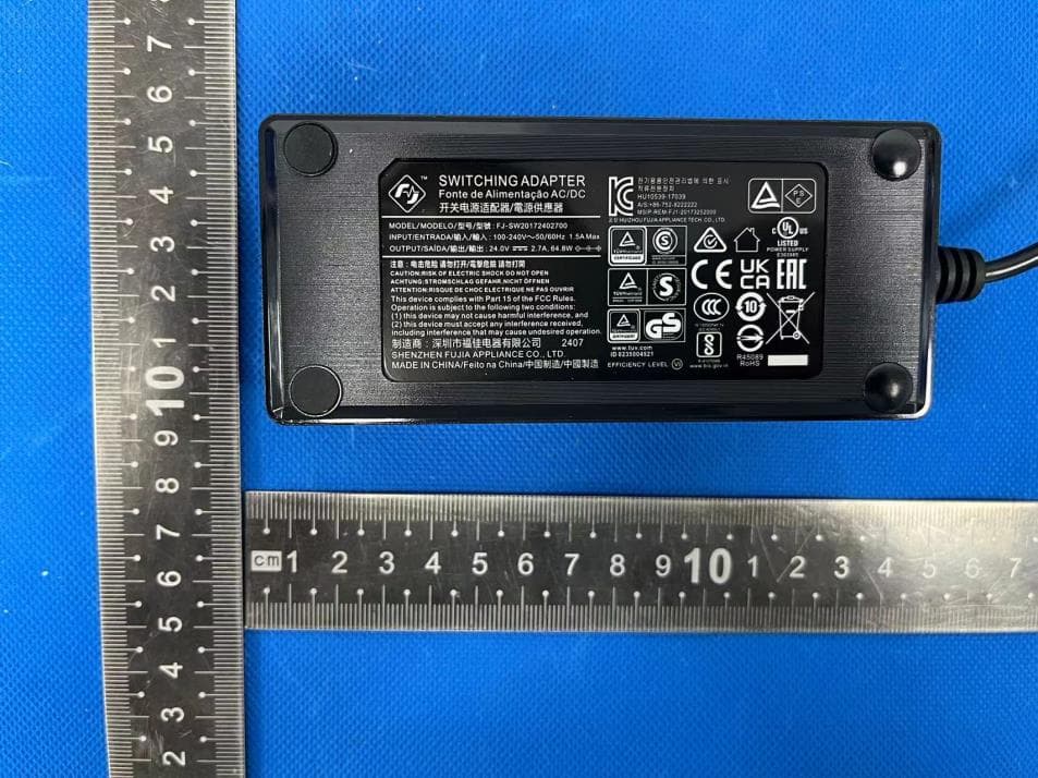
2AUA9-RQZY015
Sep 24, 2024Smart Protective Film Plotter ZC1 Max (V1.0)
Equipment Class
NII - Unlicensed National Information Infrastructure TX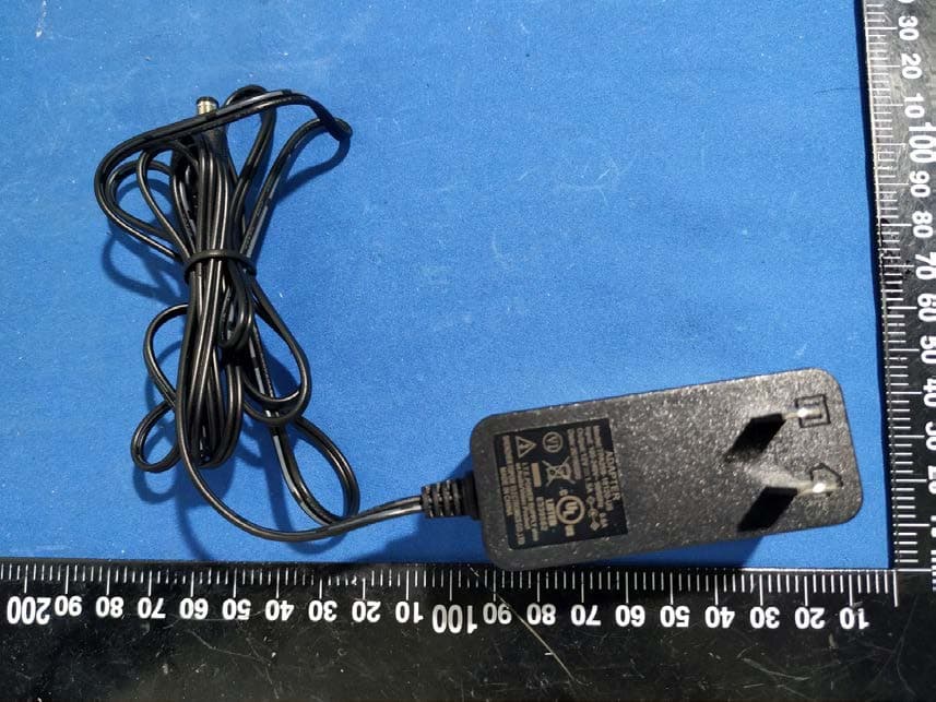
2AUA9-RQZY008
Feb 07, 2021AX1800 Dual-Band Wi-Fi 6 Router
Equipment Class
DTS - Digital Transmission System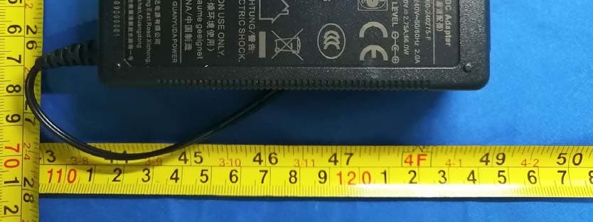
2AUA9-RQZY007
Oct 27, 2020Smart Plotter
Equipment Class
DSS - Part 15 Spread Spectrum Transmitter
2AUA9-RQZY004
Oct 11, 2020AX1800 Wi-Fi6 Smart WiFi Router
Equipment Class
DTS - Digital Transmission System
2AUA9-RQZY005
Jul 27, 2020Multi-function UVC Sterilizer(Wireless Charging)
Equipment Class
DCD - Part 15 Low Power Transmitter Below 1705 kHz