2AUCH-RIPT-ULTRABluetooth headphones
Finnovate Group, LLC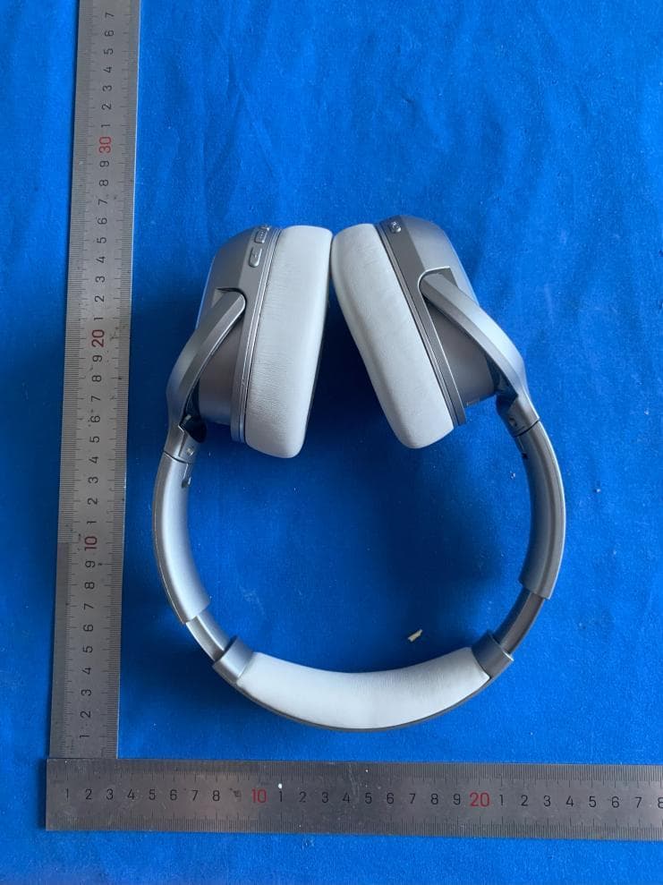
Click to zoom
Application Details
- Equipment Class
- DTS - Digital Transmission System
- Date of Grant
- Jul 20, 2025
- Application Purpose
- Original Equipment
- Equipment Note
- Bluetooth headphones
- Frequency Range
- 2402.00000000 - 2480.00000000
- Company
- Finnovate Group, LLC
- Country
- United States
Documents & Files
Document Text
Text extracted from the exhibit documents filed with the FCC. Open a document above to read the original.
Users Manual
FCC compliance statement: This device complies with Part 15 of the FCC Rules. Operation is subject to the following two conditions: (1) this device may not cause harmful interference, and (2) this device must accept any interference received, including interference that may cause undesired operation. Caution: The user is cautioned that changes or modifications not expressly approved by the party responsible for compliance could void the user's authority to operate the equipment. Note: This equipment has been tested and found to comply with the limits for a Class B digital device, pursuant to part 15 of the FCC Rules. These limits are designed to provide reasonable protection against harmful interference in a residential installation. This equipment generates, uses and can radiate radio frequency energy and, if not installed and used in accordance with the instructions, may cause harmful interference to radio communications. However, there is no guarantee that interference will not occur in a particular installation. If this equipment does cause harmful interference to radio or television reception, which can be determined by turning the equipment off and on, the user is encouraged to try to correct the interference by one or more of the following measures: —Reorient or relocate the receiving antenna. —Increase the separation between the equipment and receiver. —Connect the equipment into an outlet on a circuit different from that to which the receiver is connected. —Consult the dealer or an experienced radio/TV technician for help.
Attestation Statements
Covered Equipment Attestation Letter For Certification Service in the USA Federal Communications Commission Equipment Authorization Division, Application Processing Branch 7435 Oakland Mills Road Columbia, MD 21048 To whom it may concern Pursuant to Section 2.911(d)(5)(i)-(ii) of the Commission’s Rules (47 C.F.R.) we attest as follows for the product listed below: FCC ID Model name 2AUCH-RIPT-ULTRA RIPT-ULTRA,RIPT-ULTRA-BLK,RIPT- ULTRA-Zwift We, Applicant Company Name: Address: Phone: certify that the equipment for which authorization is sought is not “covered” equipment prohibited from receiving an equipment authorization pursuant to section 2.903 of the FCC rules. This includes the cybersecurity and anti-virus software produced or provided by Kaspersky Lab, Inc. or any of ist successors and assignees. We certify that, as of the date of the filing of the application, the applicant is not identified on the Covered List as an entity producing “covered” equipment. If you have any questions, please feel free to contact us at the address shown below. Sincerely, Jun.12,2025 Signature Date Printed Name of Signee: Kristian Rauhala Company: Finnovate Group,LLC Address: 124 E Cliff St Suite C1 Solana Beach, CA 92075 USA Phone: (858)771-4410 Fax: Email:[email protected]
Attestation Statements
LocalRepresentativeLetter ForCertificationServiceintheUSA FederalCommunicationsCommission EquipmentAuthorizationDivision,ApplicationProcessingBranch 7435OaklandMillsRoad Columbia,MD21048 Towhomitmayconcern PursuanttoSection2.911(d)(7),oftheCommission’sRules(47C.F.R.)weattestasfollowsfor theproductlistedbelow: FCCIDModelname 2BNG8-VN-FTD20-V1VN-FTD20-V1 Weherebyacknowledgeasfollows: i.bothsigneesconfirmthatthepointofcontactacceptsresponsibilitytoactasaUS- AmericanRepresentativeonbehalfoftheapplicant ii.thepointofcontactprovidesthephysicalU.S.addressandemailaslistedbelow iii.bothpartiesmaintaintherequirementsofthisagreementfornolessthanoneyear afterthegranteehasterminatedallmarketingandimportationortheconclusionof anyCommission-relatedproceedinginvolvingtheequipment. US-AmericanPointofContactApplicant/ApprovalHolder CompanyName:FinnovateGroup,LLCFinnovateGroup,LLC FRN:00287428230028742823 ContactName:KristianRauhalaKristianRauhala Address:124ECliffStSuiteC1Solana Beach,CA92075USA 124ECliffStSuiteC1Solana Beach,CA92075USA Phone:(858)771-4410(858)771-4410 Email:[email protected]@h2oaudio.com
Cover Letter(s)
Confidentiality Request Letter For Certification Service in the USA Federal Communication Commission Equipment Authorization Division, Application Processing Branch 7435 Oakland Mills Road Columbia, MD 21048 To whom it may concern Pursuant to Paragraphs §0.457 and 0.459 of the Commission’s Rules (47 C.F.R.) and Section §552(b)(4) of the Freedom of Information Act, we request confidentiality for the documentation of the following products: FCC ID Model name 2AUCH-RIPT-ULTRA RIPT-ULTRA,RIPT-ULTRA-BLK,RIPT- ULTRA-Zwift For the products listed above, we request permanent confidentiality for all applicable exhibits as there are: • the Operational Description • the Block Diagram • the Schematics The above listed exhibits contain trade secrets and proprietary information that could be of benefit to our competitors. If you have any questions, please feel free to contact us at the address shown below. Sincerely, Jun.12,2025 Signature Date Printed Name of Signee: Kristian Rauhala Company: Finnovate Group,LLC Address: 124 E Cliff St Suite C1 Solana Beach, CA 92075 USA Phone: (858)771-4410 Fax: Email: [email protected]
Cover Letter(s)
Finnovate Group,LLC 124 E Cliff St Suite C1 Solana Beach, CA 92075 USA Declaration Letter Date: Jun.17,2025 To: Federal Communications Commission Authorization and Evaluation Division 1435 Oakland Mills Road Columbia, MD 21046 To Whom It May Concern: For our business issue and marketing requirement, we would like to list different model number on the FCC certificates and reports, as following: FCC ID: 2AUCH-RIPT-ULTRA Model Number:RIPT-ULTRA,RIPT-ULTRA-BLK,RIPT-ULTRA-Zwift Model Difference: The only difference between the models is the color of appearance, the other (hardware and software) was the same as before. Sincerely, Name / Title Kristian Rauhala/Manager Company Name Finnovate Group,LLC Company Address 124 E Cliff St Suite C1 Solana Beach, CA 92075 USA Tel: (858)771-4410 Fax: Email: [email protected]
External Photos
External Photographs FCC ID: 2AUCH-RIPT-ULTRA
ID Label/Location Info
Label Sample for FCC ID: 2AUCH-RIPT-ULTRA Size for the label: 1.5cm X 1cm Product Name : Bluetooth headphones Model : RIPT-ULTRA FCC ID : 2AUCH-RIPT-ULTRA
Internal Photos
Internal photographs FCC ID: 2AUCH-RIPT-ULTRA Antenna
RF Exposure Info
MAXLAB Testing Co., Ltd. Report No.: MAX250623901601MPE Report No.: BSL250123901602MPE Page 1 of 6 MPE FCC Part 15C Measurement and Test Report For Finnovate Group,LLC FCC ID: 2AUCH-RIPT-ULTRA FCC Rule(s): FCC Part 15.247 Product Description: Bluetooth headphones Tested Model: RIPT-ULTRA Report No.: MAX250623901601MPE Tested Date: Jun.8~18,2025 Issued Date: Jun.18,2025 Tested By: Lris Yao / Engineer Reviewed By: Levi Xiao / EMC Manager Approved & Authorized By: Salon Ouyang / PSQ Manager Prepared By: MAXLAB Testing Co., Ltd. 1/F, Building B, Xinshidai GR Park, Shiyan Street, Bao'an District, Shenzhen, ShiyanStreet, Bao'an District, Shenzhen,Guangdong,518052,People’s Republic of China Tel: 400-882-9628 Fax: 86- 755-26508703 MAXLAB Testing Co., Ltd. Report No.: MAX250623901601MPE Report No.: BSL250123901602MPE Page 2 of 6 MPE 1. GENERAL INFORMATION 1.1 Product Description for Equipment Under Test (EUT) Client Information Applicant: Finnovate Group,LLC Address of applicant: 124 E Cliff St Suite C1 Solana Beach, CA 92075 USA Manufacturer: Finnovate Group,LLC Address of manufacturer: 124 E Cliff St Suite C1 Solana Beach, CA 92075 USA General Description of EUT Product Name: Bluetooth headphones Brand Name: N/A Models No.: RIPT-ULTRA,RIPT-ULTRA-BLK,RIPT-ULTRA-Zwift(The only difference between the models is the color of appearance) Rated Voltage: DC 3.7V by battery Note: The test data is gathered from a productio.0n sample provided by the manufacturer. Technical Characteristics of EUT Bluetooth Version: V5.1 Frequency Range: 2402-2480MHz Modulation: GFSK Quantity of Channels: 40 Channel Separation: 2MHz Type of Antenna: PCB Antenna Antenna Gain: 0dBi MAXLAB Testing Co., Ltd. Report No.: MAX250623901601MPE Report No.: BSL250123901602MPE Page 3 of 6 MPE 1.2 Test Standards The tests were performed according to following standards: ANSI C95.1–1999: IEEE Standard for Safety Levels with Respect to Human Exposure to Radio Frequency Electromagnetic Fields, 3 kHz to 300 GHz. FCC KDB 447498 D01 General RF Exposure Guidance v06: Mobile and Portable Device, RF Exposure, Equipment Authorization Procedures. FCC CFR 47 part1 1.1310: Radiofrequency radiation exposure limits. FCC CFR 47 part2 2.1091: Radiofrequency radiation exposure evaluation: mobile devices 1.3 Test Facility MAXLAB Testing Co., Ltd. 1/F, Building B, Xinshidai GR Park, Shiyan Street, Bao'an District, Shenzhen, ShiyanStreet, Bao'an District, Shenzhen,Guangdong,518052,People’s Republic of China FCC Test Firm Registration Number: 562200 Designation Number: CN1338 Tel: 400-882-9628 Fax: 86-755-26508703 1.4 Measurement Uncertainty Measurement uncertainty Parameter Conditions Uncertainty RF Output Power Conducted ±0.42dB MAXLAB Testing Co., Ltd. Report No.: MAX250623901601MPE Report No.: BSL250123901602MPE Page 4 of 6 MPE 2. TEST LIMIT 2.1 Requirement According to KDB447498 D01 General RF Exposure Guidance v06 Section 4.3.1 Standalone SAR test exclusion considerations: “Unless specifically required by the published RF exposure KDB procedures, standalone 1-g head or body and 10-g extremity SAR evaluation for general population exposure conditions, by measurement or numerical simulation, is not required when the corresponding SAR Test Exclusion Threshold condition, listed below, is satisfied. These test exclusion conditions are based on source-based time-averaged maximum conducted output power of the RF channel requiring evaluation, adjusted for tune-up tolerance, and the minimum test separation distance required for the exposure conditions. The minimum test separation distance is determined by the smallest distance from the antenna and radiating structures or outer surface of the device, according to the host form factor, exposure conditions and platform requirements, to any part of the body or extremity of a user or bystander (see 5) of section 4.1) To qualify for SAR test exclusion, the test separation distances applied must be fully explained and justified by the operating configurations and exposure conditions of the transmitter and applicable host platform requirements, typically in the SAR measurement or SAR analysis report, according to the required published RF exposure KDB procedures. When no other RF exposure testing or reporting is required, a statement of justification and compliance must be included in the equipment approval, in lieu of the SAR report, to qualify for the SAR test exclusion.When required, the device specific conditions described in the other published RF exposure KDB procedures must be satisfied before applying these SAR test exclusion provisions; for example, handheld PTT two-way radios, handsets, laptops & tablets etc.” [(max. power of channel, including tune-up tolerance, mW)/ (min. test separation distance, mm)] · [√f (GHz)] ≤ 3.0 for 1-g SAR and ≤ 7.5 for 10-g extremity SAR, where: • f (GHz) is the RF channel transmit frequency in GHz • Power and distance are rounded to the nearest mW and mm before calculation • The result is rounded to one decimal place for comparison • 3.0 and 7.5 are referred to as the numeric thresholds in the step 2 below The test exclusions are applicable only when the minimum test separation distance is ≤ 50 mm and for transmission frequencies between 100 MHz and 6 GHz. When the minimum test separation distance is < 5 mm, a distance of 5 mm according to 5) in section 4.1 is applied to determine SAR test exclusion. When one of the following test exclusion conditions is satisfied for all combinations of simultaneous transmission configurations, further equipment approval is not required to incorporate transmitter modules in host devices that operate in the mixed mobile and portable host platform exposure conditions. The grantee is responsible for documenting this according to Class I permissive change requirements. Antennas that qualify for standalone SAR test exclusion must apply the estimated standalone SAR to determine simultaneous transmission test exclusion. a) The [∑ of (the highest measu…
Text truncated - open the document above for the full version.
Test Report
M9-1-BT Manufacturer: Finnovate Group,LLC Address of manufacturer:124 E Cliff St Suite C1 Solana Beach, CA 92075 USA PCB Antenna
Test Report
MAXLAB TESTING CO., LTD. Report No.: MAX250623901601RF Report No.: MAX250623901601RF Page 1 of 31 FCC Part 15.247 FCC Part 15C Measurement and Test Report For Finnovate Group,LLC FCC ID: 2AUCH-RIPT-ULTRA FCC Rule(s): FCC Part 15.247 Product Description: Bluetooth headphones Tested Model: RIPT-ULTRA Report No.: MAX250623901601RF Tested Date: Jun.8~18,2025 Issued Date: Jun.18,2025 Tested By: Lris Yao / Engineer Reviewed By: Levi Xiao / EMC Manager Approved & Authorized By: Salon Ouyang / PSQ Manager Prepared By: MAXLAB TESTING CO., LTD. 1/F, Building B, Xinshidai GR Park, Shiyan Street, Bao'an District, Shenzhen, Guangdong,518052,People’s Republic of China Tel: 400-882-9628 Fax: 86- 755-26508703 MAXLAB TESTING CO., LTD. Report No.: MAX250623901601RF Report No.: MAX250623901601RF Page 2 of 31 FCC Part 15.247 TABLE OF CONTENTS 1. GENERAL INFORMATION ...................................................................................................................................... 3 1.1 PRODUCT DESCRIPTION FOR EQUIPMENT UNDER TEST (EUT) .................................................................................. 3 1.2 TEST STANDARDS ...................................................................................................................................................... 4 1.3 TEST METHODOLOGY ................................................................................................................................................ 4 1.4 TEST FACILITY .......................................................................................................................................................... 4 1.5 EUT SETUP AND TEST MODE .................................................................................................................................... 5 1.6 MEASUREMENT UNCERTAINTY ................................................................................................................................. 5 1.7 TEST EQUIPMENT LIST AND DETAILS ........................................................................................................................ 6 2. SUMMARY OF TEST RESULTS .............................................................................................................................. 7 3. RF EXPOSURE ............................................................................................................................................................ 8 3.1 STANDARD APPLICABLE ............................................................................................................................................ 8 3.2 TEST RESULT............................................................................................................................................................. 8 4. ANTENNA REQUIREMENT ..................................................................................................................................... 9 4.1 STANDARD APPLICABLE ............................................................................................................................................ 9 4.2 EVALUATION INFORMATION ..................................................................................................................................... 9 5. POWER SPECTRAL DENSITY .............................................................................................................................. 10 5.1 STANDARD APPLICABLE .......................................................................................................................................... 10 5.2 TEST PROCEDURE .................................................................................................................................................... 10 5.3 ENVIRONMENTAL CONDITIONS ............................................................................................................................... 10 5.4 SUMMARY OF TEST RESULTS/PLOTS ....................................................................................................................... 10 6. 6DB BANDWIDTH .................................................................................................................................................... 13 6.1 STANDARD APPLICABLE .......................................................................................................................................... 13 6.2 TEST PROCEDURE .................................................................................................................................................... 13 6.3 ENVIRONMENTAL CONDITIONS ............................................................................................................................... 13 6.4 SUMMARY OF TEST RESULTS/PLOTS ....................................................................................................................... 13 7. RF OUTPUT POWER ............................................................................................................................................... 16 7.1 STANDARD APPLICABLE .......................................................................................................................................... 16 7.2 TEST PROCEDURE .................................................................................................................................................... 16 7.3 ENVIRONMENTAL CONDITIONS ............................................................................................................................... 16 7.4 SUMMARY OF TEST RESULTS/PLOTS ....................................................................................................................... 16 8. FIELD STRENGTH OF SPURIOUS EMISSIONS ................................................................................................ 17 8.1 STANDARD APPLICABLE ..........................................................................................…
Text truncated - open the document above for the full version.
Test Setup Photos
Test Setup Photos FCC ID: 2AUCH-RIPT-ULTRA
Contact Information
Applicant
Kristian Rauhala(CEO)
[email protected]Fax: 858 771-4410
Test Firm
MAXLAB Testing Co., Ltd.Bill Zhao
Technical Specifications
| # | Rule Parts | Frequency Range | Power Output |
|---|---|---|---|
| 1 | 15C | 2.40 GHz - 2.48 GHz | 2.00 mW |
Other Applications from Finnovate Group, LLC
2AUCH-H2OTRI2PRO
Aug 06, 2024H2O TRI 2 PRO
Equipment Class
DSS - Part 15 Spread Spectrum Transmitter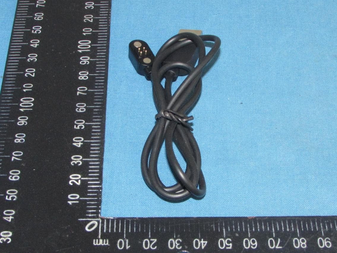
2AUCH-H2OAUDIO
Jun 05, 2023TRI PRO Multi-Sport Headphone
Equipment Class
DSS - Part 15 Spread Spectrum Transmitter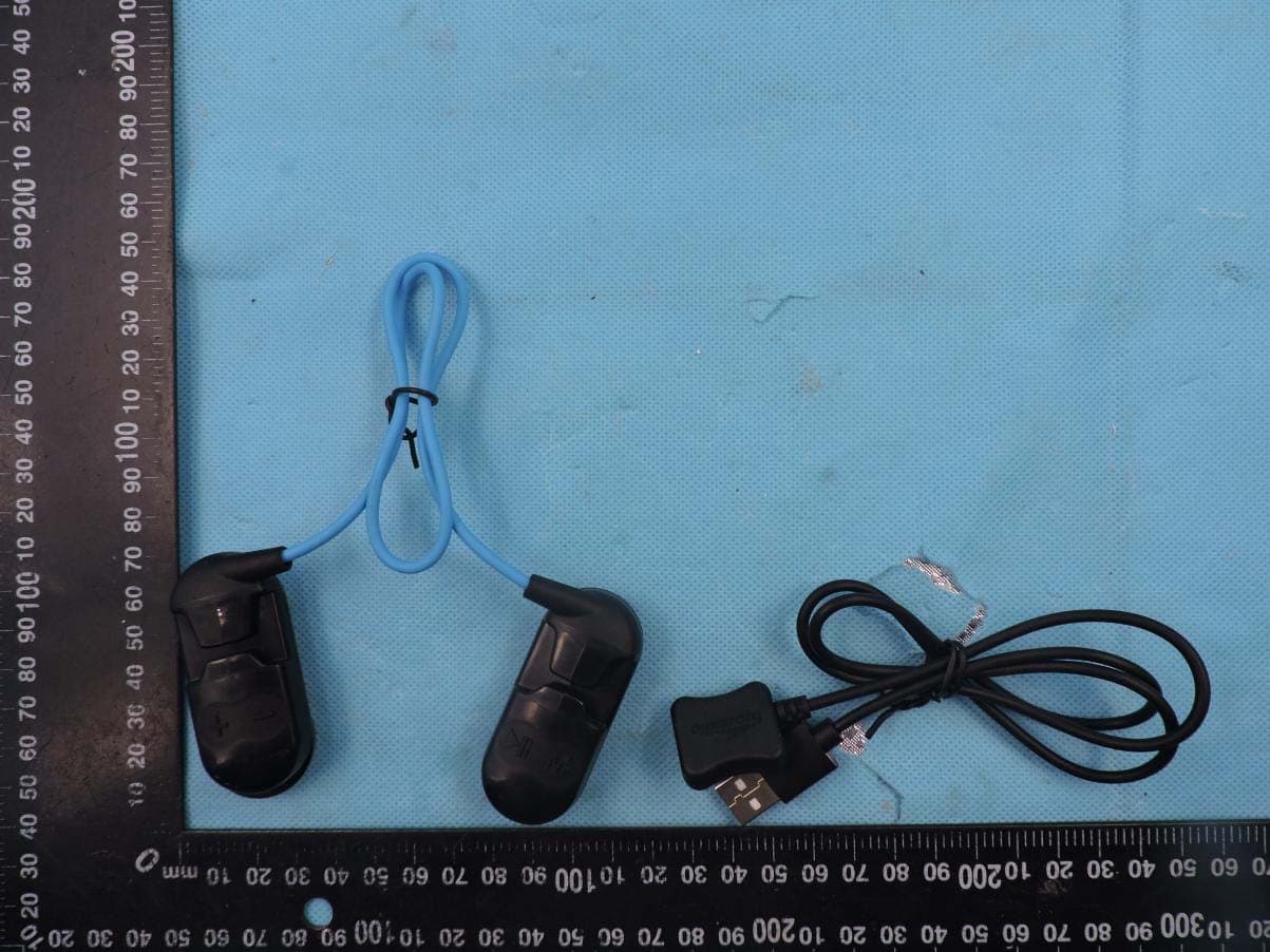
2AUCH-SONAR
Nov 14, 2020Underwater Headphones
Equipment Class
DSS - Part 15 Spread Spectrum Transmitter