2AUHN-SUNLED LIGHT
GLAMCOR GLOBAL LLC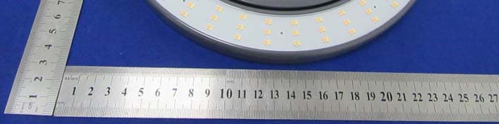
Click to zoom
Application Details
- Equipment Class
- DTS - Digital Transmission System
- Date of Grant
- Apr 12, 2020
- Application Purpose
- Original Equipment
- Date of Application
- Apr 12, 2020
- Equipment Note
- LED LIGHT
- Frequency Range
- 2402.00000000 - 2480.00000000
- Company
- GLAMCOR GLOBAL LLC
- Country
- United States
Documents & Files
Document Text
Text extracted from the exhibit documents filed with the FCC. Open a document above to read the original.
Users Manual
Quick Start Guide US and foreign Patent(s) Pending Thank you, and congratulations! :-) YOU JUST MADE THE BEST INVESTMENT INTO YOUR CAREER Your new Sunrise is the most popular light kit in the world for content creation professionals. Read through these easy instructions so you can get setup to take your first high-quality video or photo with your phone. THANK YOU We cannot thank you enough for choosing GLAMCOR to be part of your profession. We work really hard to constantly improve our products, and you can always expect something new from us. It is our commitment to you, and we are honored to be part of your professional career. STAY IN TOUCH Share your success with us! You can reach us here: Email: [email protected] Website: www.glamcor.com Instagram: @glamcorofficial Facebook: www.facebook.com/GLAMCOR NEED SERVICE OR SUPPORT? GREAT! We have legendary service supported by a team that operates almost around the clock. No matter where you are, send us an email so we can log your support issue in our system. Include your phone number so we can text or call you if you would like! Email: [email protected] Identifying the kit components 5V 2A Power Supply Included (not shown) i Carry Bag Phone Clip Remote Control Ring Light Suction Cup Battery Fold upwards to turn on right light Rotates 60 ̊ Rotating the light Push suction cup firmly onto any glass surface like a mirror or window Rotate lever in the direction of the arrow for the suction cup to create a strong suction onto the surface Attaching the suction cup Attaching the suction cup Align the clip inserts with the suction cup and slide the light down to snap it into place. Press for power Charging port Power and function controls without the remote Charging the battery Insert to charge NOTE: The SUNRISE will operate using the power supply without the battery Battery Installation NOTE: Make sure the magnets are facing downwards Attaching the Phone Clip The phone clip magnetizes onto the face of the light as shown below Attaching your Phone 360 ̊ rotation feature Safety Instructions ! PROPER USE This lamp is designed for illumination in dry indoor rooms. It is not suitable for use in damp rooms, e.g. bathrooms. The lamp must never be used for direct irradiation of persons, animals, or plants. Only use this product as described in this manual. RISK OF INJURY FOR CHILDREN, PERSON, AND ANIMALS • Keep children away from packaging - risk of suffocation! • Keep unsupervised children away from the lamp. • Do not look directly into the light source! Your eyes could be damaged. • The lamp is not suitable for irradiation of persons. • Keep animals away from the lamp! The lamp is not to be used for irradiation of animals, such as poultry, lambs etc. Risk of burning. LOCATION • Place the lamp at least 8” or 20 cm from flammable materials. • Always place the lamp on an even and stable surface to prevent tipping over. • Do not subject the device to extreme temperatures, severe changes in temperatures, direct sunlight, or moisture. • Do not allow the device to fall, and do not subject it to strong impacts. • Keep the lamp well away from heat sources such as stovetops or ovens. • Ensure that the device is not able to fall in water and cannot get wet. DO NOT SUBSTITUTE A POWER SUPPLY OTHER THAN THE INCLUDED APPROVED GLAMCOR BRANDED POWER SUPPLY OR GENUINE REPLACEMENT. Safety Instructions (con’t) ELECTRICITY - RISK OF ELECTRIC SHOCK • Keep the lamp away from humidity. • Connect the lamp only to outlets corresponding with the technical data of the lamp. • Check the lamp before each use for damage.The lamp is not to be used when it shows visible damage. • Do not take the lamp apart and only have it repaired at your local electrical store. • Before cleaning or if the lamp is not to be used for a long period, unplug the lamp from the main power supply. • During storms; unplug the lamp from the main power supply. When removing the plug from the socket, always pull on the plug and not the cable. • A damaged cable must only be repaired at your local electrical store. • Do not use the lamp if it is damaged or if the connecting cable shows any kind of visible damage. DAMAGES ON DEVICE AND MATERIALS • Do not cover lamp, for example with drapes or anything else. This could lead to fire. CHANGING BULBS • LED lights last for 20,000 hours. Do not attempt to change bulbs. CARE / MAINTENANCE • Keep the lamp away from humidity. • Unplug the lamp from the mains power supply. • Dust off the lamp if necessary with a dry cloth. ! Product Contents i SPECIFICATIONS • Unit: GLAMCOR Sunrise • Voltage supply: Input 100-240AC, Output 5V 2A • Bulb: LED • Protection class: 1 • Weight: 4.5lbs/2kg INCLUDED IN KIT • GLAMCOR Sunrise right light • 3.7V Battery • Phone clip • Suction cup • Carry bag • 5V 2A power supply • Remote control • Instruction booklet WARNING: FOR INDOOR USE ONLY This device complies with Part 15 of the FCC Rules. Operation is subject to the following two conditions: (1) this device may not cause harmful interference, and (2) this device must accept any interference received, including interference that may cause undesired operation. WARNING: Changes or modifications to this unit not expressly approved by the party responsible for compliance could void the user’s authority to operate the equipment. NOTE: This equipment has been tested and found to comply with the limits for a Class B digital device, pursuant to Part 15 of the FCC Rules. These limits are designed to provide reasonable protection against harmful interference in a residential installation. This equipment generates, uses, and can radiate radio frequency energy and, if not installed and used in accordance with the instructions, may cause harmful interference to radio communications. However, there is no guarantee that interference will not occur in a particular installation. If this equipment does cause harmful interference to radio or television reception, which can be determined by turning the e…
Text truncated - open the document above for the full version.
External Photos
External Photos
ID Label/Location Info
40*20mm Label Location FCC ID: 2AUHN-SUN This device complies with Part 15 of the FCC Rules. Operation is subject to the following two conditions:(1)This device may not cause harmful interference, and (2) this device must accept any interference received, including interference that may cause und esired operation.
Internal Photos
Internal Photos Antenna
RF Exposure Info
Shenzhen BCTC Testing Co., Ltd. FCC ID: 2AUHN-SUN Portable device According to §15.247(e)(i) and §1.1307(b)(1), systems operating under the provisions of this section shall be operated in a manner that ensures that the public is not exposed to radio frequency energy level in excess of the Commission’s guidelines. According to KDB447498 D01 General RF Exposure Guidance V06 The 1-g SAR and 10-g SAR test exclusion thresholds for 100 MHz to 6 GHz at test separation distances ≤ 50 mm are determined by: [(max. power of channel, including tune-up tolerance, mW)/(min. test separation distance, mm)]·[√f(GHZ)] ≤ 3.0 for 1-g SAR and ≤ 7.5 for 10-g extremity SAR, where: • f(GHZ) is the RF channel transmit frequency in GHz • Power and distance are rounded to the nearest mW and mm before calculation • The result is rounded to one decimal place for comparison When the minimum test separation distance is < 5 mm, a distance of 5 mm is applied to determine SAR test exclusion. Modulation Channel Freq. (GHz) Conduct ed power (dBm) Conducte d power (mW) Tune-up power (dBm) Max tune-up power (dBm) Max tune-up power (mW) Distance (mm) Result calculatio n SAR Exclusion threshold SAR test exclusion GFSK2.402-5.810.26-5±1-4.000.40<50.123403.00YES GFSK2.440-4.860.33-5±1-4.000.40<50.124373.00YES GFSK2.480-4.310.37-5±1-4.000.40<50.125393.00YES Conclusion: For the max result : 0.12340≤3.0, the SAR testing is not required.
Test Report
Shenzhen BCTC Testing Co., Ltd. Report No.: BCTC2003000615E Test Report Tel: 400-788-9558 Web: https://www.bctc-lab.com BCTC/RF-EMC-007 Ver.:A.0 Page 1 of 42 Test Report FCC: 2AUHN-SUN Product Name: LED LIGHT Trademark: Model Name : Sunrise Prepared For : GLAMCOR GLOBAL LLC Address : 110 Wall Street, 5th Floor, Manhattan NY10005 United States Prepared By : Shenzhen BCTC Testing Co., Ltd. Address : BCTC Building & 1-2F, East of B Building, Pengzhou Industrial, Fuyuan 1st Road, Qiaotou Community, Fuyong Street, Bao’an District, Shenzhen, China Test Date: Mar. 17, 2020 – Mar. 25, 2020 Date of Report : Mar. 25, 2020 Report No.: BCTC2003000615E Shenzhen BCTC Testing Co., Ltd. Report No.: BCTC2003000615E Test Report Tel: 400-788-9558 Web: https://www.bctc-lab.com BCTC/RF-EMC-007 Ver.:A.0 Page 2 of 42 TEST RESULT CERTIFICATION Applicant’s name ................. : GLAMCOR GLOBAL LLC Address ................................. : 110 Wall Street, 5th Floor, Manhattan NY10005 United States Manufacture's Name ............ : GLAMCOR GLOBAL LLC Address ................................. : 110 Wall Street, 5th Floor, Manhattan NY10005 United States Product description Product name ........................... : LED LIGHT Trademark ................................. : Model and/or type reference : Sunrise Standards ............................. : FCC Part15.247 ANSI C63.10:2013 This device described above has been tested by BCTC, and the test results show that the equipment under test (EUT) is in compliance with the FCC requirements. And it is applicable only to the tested sample identified in the report. This report shall not be reproduced except in full, without the written approval of BCTC, this document may be altered or revised by BCTC, personal only, and shall be noted in the revision of the document. Prepared by(Engineer): Cai Fang Zhong Reviewer(Supervisor): Eric Yang Approved(Manager): Zero Zhou Shenzhen BCTC Testing Co., Ltd. Report No.: BCTC2003000615E Test Report Tel: 400-788-9558 Web: https://www.bctc-lab.com BCTC/RF-EMC-007 Ver.:A.0 Page 3 of 42 Table of Contents Page 1 . SUMMARY OF TEST RESULTS 5 1.1 TEST FACILITY 6 1.2 MEASUREMENT UNCERTAINTY 6 2 . GENERAL INFORMATION 7 2.1 GENERAL DESCRIPTION OF EUT 7 2.2 DESCRIPTION OF TEST MODES 8 2.3 BLOCK DIGRAM SHOWING THE CONFIGURATION OF SYSTEM TESTED 9 2.4 DESCRIPTION OF SUPPORT UNITS(CONDUCTED MODE) 9 2.5 EQUIPMENTS LIST FOR ALL TEST ITEMS 10 3 . EMC EMISSION TEST 11 3.1 CONDUCTED EMISSION MEASUREMENT 11 3.1.1 POWER LINE CONDUCTED EMISSION LIMITS 11 3.1.2 TEST PROCEDURE 11 3.1.3 DEVIATION FROM TEST STANDARD 11 3.1.4 TEST SETUP 12 3.1.5 EUT OPERATING CONDITIONS 12 3.1.6 TEST RESULTS 12 3.2 RADIATED EMISSION MEASUREMENT 15 3.2.1 RADIATED EMISSION LIMITS 15 3.2.2 TEST PROCEDURE 16 3.2.3 DEVIATION FROM TEST STANDARD 16 3.2.4 TEST SETUP 16 3.2.5 EUT OPERATING CONDITIONS 18 3.2.6 TEST RESULTS (BETWEEN 9KHZ – 30 MHZ) 19 3.2.7 TEST RESULTS (BETWEEN 30MHZ – 1GHZ) 20 3.3 RADIATED BAND EMISSION MEASUREMENT AND RESTRICTED BANDS OF OPERATION 23 3.3.1 TEST REQUIREMENT: 23 3.3.2 TEST PROCEDURE 23 3.3.3 DEVIATION FROM TEST STANDARD 24 3.3.4 TEST SETUP 24 3.3.5 EUT OPERATING CONDITIONS 24 4 . POWER SPECTRAL DENSITY TEST 26 4.1 APPLIED PROCEDURES / LIMIT 26 Shenzhen BCTC Testing Co., Ltd. Report No.: BCTC2003000615E Test Report Tel: 400-788-9558 Web: https://www.bctc-lab.com BCTC/RF-EMC-007 Ver.:A.0 Page 4 of 42 Table of Contents Page 4.1.1 TEST PROCEDURE 26 4.1.2 DEVIATION FROM STANDARD 26 4.1.3 TEST SETUP 26 4.1.4 EUT OPERATION CONDITIONS 26 4.1.5 TEST RESULTS 27 5 . BANDWIDTH TEST 29 5.1 APPLIED PROCEDURES / LIMIT 29 5.1.1 TEST PROCEDURE 29 5.1.2 DEVIATION FROM STANDARD 29 5.1.3 TEST SETUP 29 5.1.4 EUT OPERATION CONDITIONS 29 5.1.5 TEST RESULTS 30 6 . PEAK OUTPUT POWER TEST 32 6.1 APPLIED PROCEDURES / LIMIT 32 6.1.1 TEST PROCEDURE 32 6.1.2 DEVIATION FROM STANDARD 32 6.1.3 TEST SETUP 32 6.1.4 EUT OPERATION CONDITIONS 32 6.1.5 TEST RESULTS 33 7 . 100 KHZ BANDWIDTH OF FREQUENCY BAND EDGE 34 7.1 APPLICABLE STANDARD 34 7.2 TEST PROCEDURE 34 7.3 DEVIATION FROM STANDARD 34 7.4 TEST SETUP 34 7.5 EUT OPERATION CONDITIONS 34 8 . DUTY CYCLE OF TEST SIGNAL 37 8.1 STANDARD REQUIREMENT 37 8.2 FORMULA 37 9 . ANTENNA REQUIREMENT 38 9.1 STANDARD REQUIREMENT 38 9.2 EUT ANTENNA 38 10 . EUT TEST PHOTO 39 11 . EUT PHOTO 41 APPENDIX-PHOTOGRAPHS OF EUT CONSTRUCTIONAL DETAILS Shenzhen BCTC Testing Co., Ltd. Report No.: BCTC2003000615E Test Report Tel: 400-788-9558 Web: https://www.bctc-lab.com BCTC/RF-EMC-007 Ver.:A.0 Page 5 of 42 1. SUMMARY OF TEST RESULTS Test procedures according to the technical standards: FCC Part15 (15.247) , Subpart C Standard Section Test Item Judgment Remark 15.207 Conducted Emission PASS 15.247 (a)(2) 6dB Bandwidth PASS 15.247 (b) Peak Output Power PASS 15.247 (d), 15.205 Radiated Spurious Emission PASS 15.247 (e) Power Spectral Density PASS 15.205 Restricted Band of Operation PASS 15.247(d) Band Edge (Out of Band Emissions) PASS 15.203 Antenna Requirement PASS NOTE: (1)” N/A” denotes test is not applicable in this Test Report Shenzhen BCTC Testing Co., Ltd. Report No.: BCTC2003000615E Test Report Tel: 400-788-9558 Web: https://www.bctc-lab.com BCTC/RF-EMC-007 Ver.:A.0 Page 6 of 42 1.1 TEST FACILITY Shenzhen BCTC Testing Co., Ltd. Add.: BCTC Building & 1-2F, East of B Building, Pengzhou Industrial, Fuyuan 1st Road, Qiaotou Community, Fuyong Street, Bao’an District, Shenzhen, China FCC Test Firm Registration Number: 712850 IC Registered No.: 23583 1.2 MEASUREMENT UNCERTAINTY The reported uncertainty of measurement y ± U,where expended uncertainty U is based on a standard uncertainty multiplied by a coverage factor of k=2,providing a level of confidence of approximately 95 %。 No. Item Uncertainty 1 3m camber Radiated spurious emission(30MHz-1GHz) U=4.3dB 2 3m chamber Radiated spurious emission(1GHz-18GHz) U=4.5dB 3 3m chamber Radiated spurious emission(18GHz-40GHz) U=3.34dB 4 Conducted Adjacent channel power U=1.38dB 5 Conducted output power uncertainty Above 1G …
Text truncated - open the document above for the full version.
Test Setup Photos
Shenzhen BCTC Testing Co., Ltd. Conducted Emission Shenzhen BCTC Testing Co., Ltd. Radiated Measurement Photos
Contact Information
Applicant
Erik.A. Kaiser
Technical Contact
Shenzhen BCTC Testing Co., Ltd.Alan Mei
[email protected]86-755-36882589
BCTC Bldg&1-2F,East of B Bldg,Pengzhou Industrial · Baoan District, Shenzhen · China
Test Firm
Shenzhen BCTC Testing Co., Ltd.Alan Mei
[email protected]+8675536882589
Technical Specifications
| # | Rule Parts | Frequency Range | Power Output |
|---|---|---|---|
| 1 | 15C | 2.40 GHz - 2.48 GHz | 370.00 µW |
Other Applications from GLAMCOR GLOBAL LLC
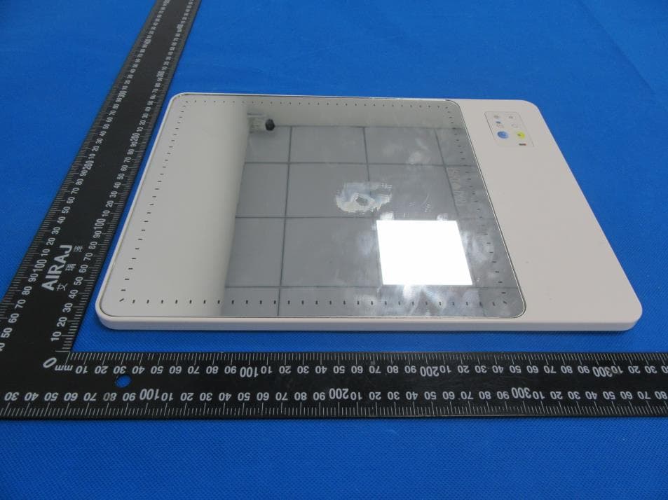
2AUHN-RIKISKINNYDUO
Mar 02, 2023LED Lighted Mirror
Equipment Class
DTS - Digital Transmission System
2AUHN-HOLLYWOOD-L
Nov 08, 2022LED Lighted Mirror
Equipment Class
DTS - Digital Transmission System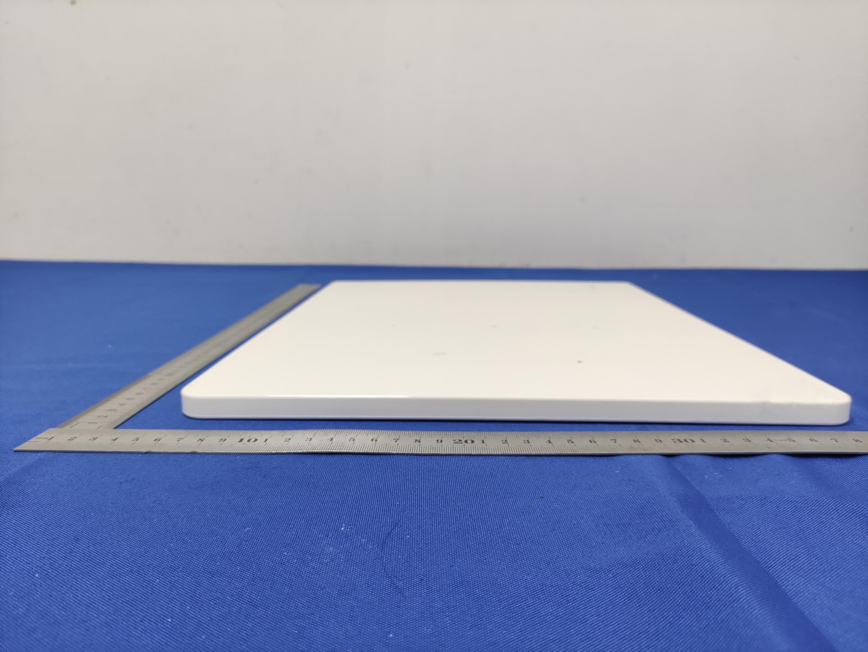
2AUHN-RIKIPRETTY
Jun 03, 2021LED Lighted Mirror
Equipment Class
DTS - Digital Transmission System
2AUHN-GALILEO
Aug 16, 2020LED LIGHT
Equipment Class
DSS - Part 15 Spread Spectrum Transmitter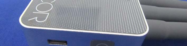
2AUHN-MULTIMEDIA
Apr 09, 2020LED LIGHT
Equipment Class
DTS - Digital Transmission System