2AUPH-VX508Marine Amp
Velex Tech Ltd.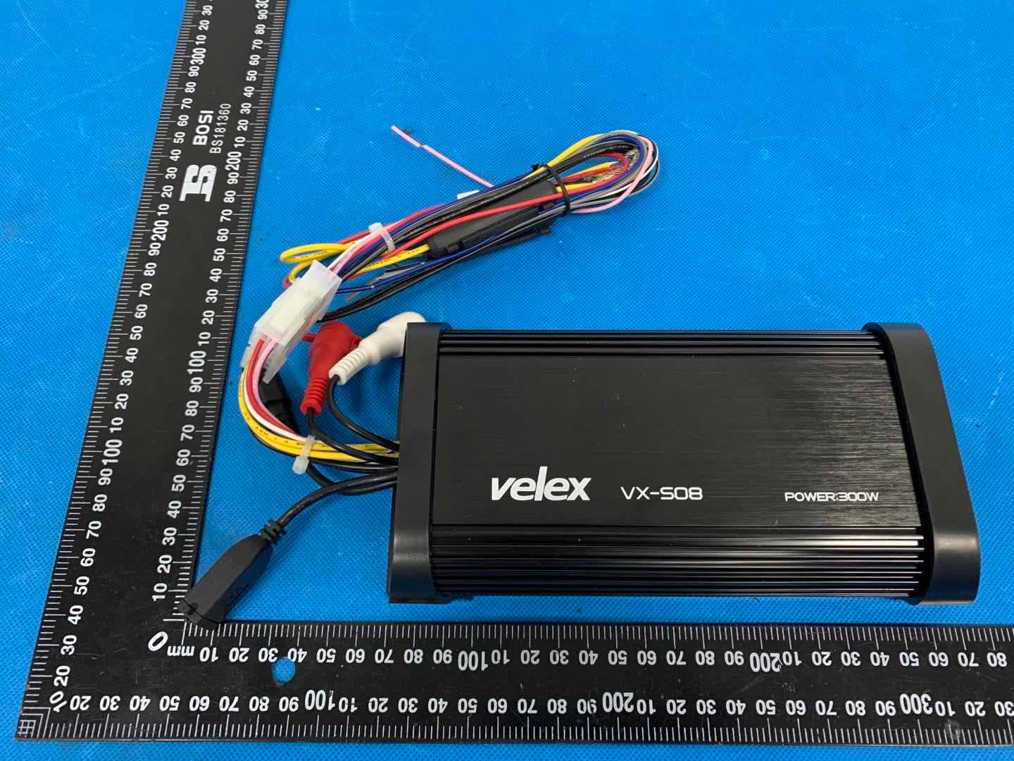
Click to zoom
Application Details
- Equipment Class
- DXX - Part 15 Low Power Communication Device Transmitter
- Date of Grant
- Mar 11, 2021
- Application Purpose
- Original Equipment
- Date of Application
- Mar 11, 2021
- Equipment Note
- Marine Amp
- Frequency Range
- 2402.00000000 - 2480.00000000
- Company
- Velex Tech Ltd.
- Country
- China
Documents & Files
Document Text
Text extracted from the exhibit documents filed with the FCC. Open a document above to read the original.
Users Manual
Please read through these instructions carefully so you will know how to operate your model properly. Thank you for purchasing this VX508 Bluetooth Amplifier After you have finished reading the instructions, keep this document in a safe place for future reference. THIS PACKAGE CONTAINS 1-VX508 Bluetooth 2-CH Class D Amplifier 1-Multi-Function Controller 1-Flush Mount Bezel (preinstalled on the remote) 1-Handleber Mounting Bracket & Hardware Kit 1-Power Harness 1-User Manual BEFORE YOU START IMPORTANT SAFETY PRECAUTIONS BE SURE TO OBSERVE THE FOLLOWING GUIDELINES: - Do not turn up the volume so high that you can't hear what's around you. - Use caution or temporarily discontinue use in potentially hazardous situations. Do not operate mobile video equipment while driving a motorized vehicle - safe driving and safety consideration of others should always be your highest priority. Set your volume control at a low setting, then slowly increase the sound until you can hear it comfortably without distortion, or ear discomfort. In the event you should notice smoke, strange noises or odor from this product, or any other abnormal signs, immediately turn off the power and consult technician. Using this product in this condition may result in permanent damage to the system. INSTALLATION PRECAUTIONS WARNING Always consult with a professional installer Do not attempt to install or service this product by yourself. Installation or servicing of this product by persons without professional training and experience in electronic equipment and motorized vehicle accessories may be dangerous and could expose you to the risk of electric shock, injury or other hazards. VX508 should be powered directly to a vehicle battery When wiring directly to vehicle battery, be sure to disconnect the batteries negative terminal wire before starting any wiring procedures, if extending the main power wire, it is suggested that an optional fuse and fuse holder (not included) with minimum rating of 20 Amperes be in-line with the positive battery terminal. The ground cable length should not exceed 18-inches (See wiring diagram PG 4) The VX508 has a weather resistant design, it should not be submerged in or under water under any circumstances Use only the installation parts provided with the VX508 CAUTIONS!! Using other mounting methods may void this warranty 2 WIRE DIAGRAM CAUTION!! Do not ground or short the PINK antenna wire 3 WHITE WHITE/BLK + - RMS 150W 4-OHM SPEAKERS LEFT CHANNEL 1 GRAY GRAY/BLK + - RIGHT CHANNEL 1 REMOTE OUT (500mA MAX) +12V BLUE +12V RED IGNITION +12V YELLOW BATTERY FUSE REPLACEMENT BATTERY CHASSIS GROUND POINT DIRECT BATTERY WIRING CIRCUIT PINK ANTENNA (DO NOT CUT) BLACK CHASSIS GROUND PIONT VX502 SRC INSERT REMOTE CONTROL USB CHARGING (1A MAX) (R) INPUT RED (L) INPUT WHITE RCA TO 3.5mm ADAPTOR NOT INCLUDED 1 14 10 AMP BLK BLACK 10 AMP BEFORE INSTALLING THIS PRODUCT To avoid potential shorts in the electrical system, be sure to disconnect the (-) battery cable before installation. Use this unit with a 12-volt battery and negative grounding only. Failure to do so may result in a fire or malfunction. TOOLS NEEDED: -Wrench and/or Pliers -#2 Philips screwdriver -Crimp tool -Electrical tape 4 When replacing the fuse, be sure to only use a fuse of the rating specified on this product. To avoid short-circuiting, cover any disconnected lead with insulating tape. It is especially important to insulate any unused wires, which if left uncovered may cause a short circuit. When connecting other devices to this product, refer to the manual for the product to be connected. The black cable is ground, make sure to connect the ground wire first. Ensure that the ground cable is properly connected to metal parts of the vehicles body frame or direct to the battery if your vehicle does not have a grounded chassis frame. The ground cable of this units power amp and a second powered system must be connected to the frame separately with different screws. If the screw for the ground wire loosens or falls out, it could result in fire or malfunction. CAUTION RISK OF ELECTRIC SHOCK DO NOT OPEN CAUTION: TO REDUCE THE RISK OF ELECTRIC SHOCK DO NOT REMOVE COVER (OR BACK). NO USER-SERVICEABLE PARTS INSIDE. REFER SERVICING TO QUALIFIED SERVICE PERSONNEL. SUGGESTED MOUNTING METHODS 5 The VX508 can mounted in three different configurations: The flush mount quick mount bezel requires no screws Use cutout dimensions: 3-3/16” W x 1-11/16” H (82mm x 43mm) 1 Flush Mount MULTI-FUNCTION CONTROLLER UNIT CUTOUT HOLE The flush mount bezel has two recessed screw holes to facilitate the included two oval-head screws. 2 Surface Mount MULTI-FUNCTION CONTROLLER UNIT To release the VX508 controller from the mounting bezel, insert a small jewelers screwdriver into the left/right slots of the bezel. Tips: Use provided pan-head screws and stainless steel clamp, there are three mounting variations to secure the stainless steel clamp, try the best one for your application, securely tighten the stainless clamp to fit your application. 3 HANDLEBAR MOUNT MULTI-FUNCTION CONTROLLER UNIT VX502 SRC VX502 SRC HANDLEBAR CLAMP LEFTRIGHTor GETTING STARTED 6 GETTING TO KNOW YOUR VX508 MULTIFUNCTION CONTROLLER (MFC) MFC-MULTIFUNCTIONAL CONTORLLER SRC PURPLE = AUX IN / RED = USB MODE = BLUETOOTH VOLUME UP SHORT PRESS - NEXT TRACK / LONG PRESS – EQ SETTING PLAY / PAUSE VOLUME DOWN SHORT PRESS – PREVIOUS TRACK / LONG PRESS- EQ SETTING 1 2 3 4 5 6 7 SRC 1 3 2 6 5 7 4 BLUETOOTH OPERATION 7 PAIRING & DISCOVERING A NEW BLUETOOTH CONNECTION To avoid battery exhaustion be sure to run the vehicles engine while using this product. Using this product without running the engine can drain the battery. Tips: SRC 2 2 1. Power on the VX508 by short press the SRC button, the Bluetooth blue LED will be switched on, a confirmation tone will be heard, signaling that VX508 is now ready for Bluetooth pairing. 2. Now that the VX508 (VELEX) is in pairing mode: Android users: a. Go into the Setting …
Text truncated - open the document above for the full version.
Attestation Statements
Velex Tech Ltd. Model Difference Product Name: Marine Amp Model Number: VX508 VX502, VX503, VX504, VX505, VX506, VX507, VX508, VX509, VX510 FCC Identifier: 2AUPH-VX508 All the models are the same circuit and RF module, except the mode names and outlook color. Regards Sincerely Client’s signature Client’s name / title: Hauer Huang / Manager Contact information: 2F, Bldg F, Jin Guang Industry Park, 17-1 Pingxi South Road, Pingdi, Shenzhen, China
Cover Letter(s)
Velex Tech Ltd. 1/1 Letter of Authorization Company: Velex Tech Ltd. Address: 2F, Bldg F, Jin Guang Industry Park, 17-1 Pingxi South Road, Pingdi, Shenzhen, China Product Name: Marine Amp Model Number: VX508 VX502, VX503, VX504, VX505, VX506, VX507, VX508, VX509, VX510 FCC Identifier: 2AUPH-VX508 We authorize LGAI Technological Center S.A., Ronda de la Font del Carme, s/n, 08193 Bellaterra, Spain, to act on our behalf on all matters concerning the above named equipment. Any individual within LGAI Technological Center S.A. is authorized to act on our behalf and take action on the application. We declare that authorize LGAI Technological Center S.A., Ronda de la Font del Carme, s/n, 08193 Bellaterra, Spain, is allowed to forward all information related to the approval project to the Federal Communication Commission and to discuss any issues concerning the approval application. Any and all acts carried out by LGAI Technological Center S.A. on our behalf shall have the same effect as acts of our own. Name: Hauer Huang Date: 2021-03-02 Title: Manager Signature of applicant:
Cover Letter(s)
Velex Tech Ltd. 1/1 Office of Engineering Technology Federal Communications Commission 7435 Oakland Mills Road Columbia, MD 21046 Date: 2021-03-02 Subject: Request for Confidentiality FCC ID: 2AUPH-VX508 To Whom It May Concern, Pursuant to the provisions of Sections 0.457 and 0.459 of Commission's rules (47CFR0.457, 0.459), we are requesting the Commission to withhold the following attachment(s) as confidential document from public disclosure. Exhibits Long-Term Confidentiality Short-Term Confidentiality NOTE 2 ID Label/Location No No Attestation Statement No No External Photos No ☐ Block Diagram ☒ ☐ Schematics ☒ ☐ Test Report No No Test Setup Photos No ☐ User’s Manual No ☐ Internal Photos No ☐ Parts List / Tune Up ☐ ☐ RF Exposure Info No No Operational Description ☒ ☐ Cover Letter(s) No No SDR Software / Security Info ☐ No NOTE 1: Long-Term Confidentiality may be permitted under special conditions (See II. LONG-TERM CONFIDENTIALITY, Section 3 of KDB 726920, use last in force) NOTE 2: Short-Term Confidentiality can be requested for a maximum of 180 days from the date of the grant. Above mentioned document contains detailed system and equipment description are considered as proprietary information in operation of the equipment. The public disclosure of above documents might be harmful to our company and would give competitor an unfair advantage in the market. It is our understanding that all measurement test reports, FCC ID label format and correspondent during certification review process cannot be granted as confidential documents and those information will be available for public review once the grant of equipment authorization is issued. Sincerely, Signature: Name: Hauer Huang Title: Manager
External Photos
Model: VX508
ID Label/Location Info
Size:17*10.5mm M/N: VX508 FCC ID: 2AUPH-VX508 Label location
Internal Photos
Model: VX508 Antenna location
Test Report
Global United Technology Services Co., Ltd. Report No.: GTSL202102000058F01 Authorized Signature: Robinson Luo Laboratory Manager This results shown in this test report refer only to the sample(s) tested, this test report cannot be reproduced, except in full, without prior written permission of the company. The report would be invalid without specific stamp of test institute and the signatures of compiler and approver. Page 1 of 31 + TEST REPORT Applicant: Velex Tech Ltd. Address of Applicant: 2F, Bldg F, Jin Guang Industry Park, 17-1 Pingxi South Road, Pingdi, Shenzhen, China Manufacturer: Velex Tech Ltd. Address of Manufacturer: 2F, Bldg F, Jin Guang Industry Park, 17-1 Pingxi South Road, Pingdi, Shenzhen, China Equipment Under Test (EUT) Product Name: Marine Amp Model No.: VX508 VX502, VX503, VX504, VX505, VX506, VX507, VX508, VX509, VX510 Trade Mark: Velex FCC ID: 2AUPH-VX508 Applicable standards: FCC CFR Title 47 Part 15 Subpart C Section 15.249 Date of sample receipt: Feb. 05, 2021 Date of Test: Feb. 05, 2021 - Mar. 03, 2021 Date of report issued: Mar. 03, 2021 Test Result: PASS * * In the configuration tested, the EUT complied with the standards specified above. Report No.: GTSL202102000058F01 Global United Technology Services Co., Ltd. No. 123-128, Tower A, Jinyuan Business Building, No.2, Laodong Industrial Zone, Xixiang Road, Baoan District, Shenzhen, Guangdong, China 518102 Telephone: +86 (0) 755 2779 8480 Fax: +86 (0) 755 2779 8960 Page 2 of 31 Version Version No. Date Description 00 Mar. 03, 2021 Original Prepared By: Date: Mar. 03, 2021 Project Engineer Check By: Date: Mar. 03, 2021 Reviewer Report No.: GTSL202102000058F01 Global United Technology Services Co., Ltd. No. 123-128, Tower A, Jinyuan Business Building, No.2, Laodong Industrial Zone, Xixiang Road, Baoan District, Shenzhen, Guangdong, China 518102 Telephone: +86 (0) 755 2779 8480 Fax: +86 (0) 755 2779 8960 Page 3 of 31 2 Contents Page 1 COVER PAGE .............................................................................................................................................1 2 VERSION ...................................................................................................................................................2 3 CONTENTS ...............................................................................................................................................3 4 TEST SUMMARY ......................................................................................................................................4 4.1 MEASUREMENT UNCERTAINTY .............................................................................................................4 5 GENERAL INFORMATION .......................................................................................................................5 5.1 GENERAL DESCRIPTION OF EUT ..........................................................................................................5 5.2 TEST MODE .........................................................................................................................................7 5.3 DESCRIPTION OF SUPPORT UNITS ........................................................................................................7 5.4 DEVIATION FROM STANDARDS ..............................................................................................................7 5.5 ABNORMALITIES FROM STANDARD CONDITIONS ....................................................................................7 5.6 TEST FACILITY ....................................................................................................................................8 5.7 TEST LOCATION ..................................................................................................................................8 5.8 ADDITIONAL INSTRUCTIONS ..................................................................................................................8 6 TEST INSTRUMENTS LIST ......................................................................................................................9 7 TEST RESULTS AND MEASUREMENT DATA .....................................................................................11 7.1 ANTENNA REQUIREMENT ....................................................................................................................11 7.2 CONDUCTED EMISSIONS ....................................................................................................................12 7.3 RADIATED EMISSION METHOD ............................................................................................................13 7.3.1 Field Strength of The Fundamental Signal ..................................................................................15 7.3.2 Spurious emissions .....................................................................................................................16 7.3.3 Bandedge emissions ...................................................................................................................21 7.4 20DB OCCUPY BANDWIDTH ...............................................................................................................22 8 TEST SETUP PHOTO .............................................................................................................................24 9 EUT CONSTRUCTIONAL DETAILS .......................................................................................................25 Report No.: GTSL202102000058F01 Global United Technology Services Co., Ltd. No. 123-128, Tower A, Jinyuan Business Building, No.2, Laodong Industrial Zone, Xixiang Road, Baoan District, Shenzhen, Guangdong, China 518102 Telephone: +86 (0) 755 2779 8480 Fax: +86 (0) 755 2779 8960 Page 4 of 31 3 Test Summary Test Item Section in CFR 47 Result Antenna requirement 15.203 Pass AC Power Line Conducted Emission 15.207 N/A Field strength of the fundamental signal 15.249 (a) …
Text truncated - open the document above for the full version.
Test Setup Photos
Measurement Photos Model: VX508
Contact Information
Applicant
Hauer Huang
Technical Contact
Global United Technology Services Co. Ltd.robinson lo
[email protected]86-0-755-2779-8480
Shenzhen · China
Test Firm
Global United Technology Services Co. Ltd.Robinson Lo
Technical Specifications
| # | Rule Parts | Frequency Range | Power Output |
|---|---|---|---|
| 1 | 15C | 2.40 GHz - 2.48 GHz | - |
Other Applications from Velex Tech Ltd.
2AUPH-VX163
Mar 11, 2021Marine Stereo
Equipment Class
DXX - Part 15 Low Power Communication Device Transmitter
2AUPH-VX230
Mar 10, 2021Marine Stereo
Equipment Class
DXX - Part 15 Low Power Communication Device Transmitter