2AVHACV1-03NOLO Base Station
Beijing Lingyu century Information Technology Co., Ltd.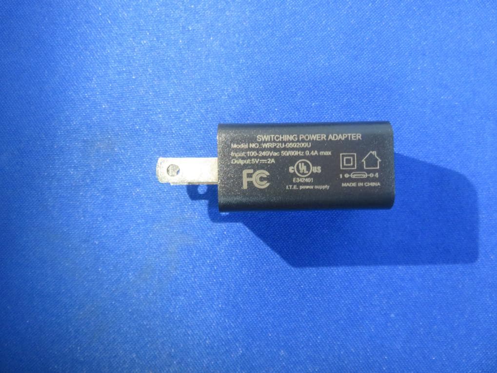
Click to zoom
Application Details
- Equipment Class
- DXT - Part 15 Low Power Transceiver, Rx Verified
- Date of Grant
- Mar 01, 2020
- Application Purpose
- Original Equipment
- Date of Application
- Mar 01, 2020
- Equipment Note
- NOLO Base Station
- Frequency Range
- 2402.00000000 - 2475.00000000
- Country
- China
Documents & Files
Document Text
Text extracted from the exhibit documents filed with the FCC. Open a document above to read the original.
Users Manual
NOLO使用说明 NOLO Instructions 详细使用教程,请访问官网(www.nolovr.com/getstarted/)进行査看。 For detailed instructions, please visit the official website (www.nolovr.com/getstarted) 包装内容 Package Contents 定位基站X1 交互手柄X2 头盔定位器X1 Model:CV1 PRO PositioningBaseStation*1 InteractiveController*2 HeadsetMarker*1 电源适配器X1 一字型定位器卡座X1 L型定位器卡座X1 PowerAdapter*1 SlottedPositionerSocket*1 L-typePositionerSocket*1 一分三充电线X1 OTG数据线X2 1米数据线X1 一字型定位器卡座X1 Three-In-OneChargingCable*1 OTGDataCable*2 1mDataCable*1 SlottedPositionerSocket*1 了解设备 LearnMoreabouttheDevice 交互手柄 1扳机键 2配对键 3侧按键 4触控板 5菜单键 6指示灯 7系统/电源键 InteractiveController 1TriggerKey 2PairingKey 3SideKeys(Eachfortheleftandrightsides) 4TouchKey 5MenuKey 6IndicatorLamp 7System/PowerKey 定位基站 电源键 配对键 PositioningBaseStation PowerKey PairingKey 头盔定位器 指示灯 USB接口 配对键 HeadsetMarker IndicatorLamp USBInterface PairingKey 一.配合VR—体机使用说明 I.InstructionsforStandaloneHeadsets 1.搭建网络环境 1.Setupthenetworkenvironment 将路由器和电脑通过网线连接; 将VR—体机和电脑连接至同一路由器的5GWi-Fi频段。 Connecttherouterandthecomputerwiththenetworkcable; Connectthestandaloneheadsetsandcomputertothe5GWi-Fibandofthesamerouter. 2.电脑软件准备 2.SoftwarePreparationofPCs 电脑下裁并安装NOLOHOMEWindows版(http://download.nolovr.com)。 DownloadandinstalltheWindowsversionofNOLOHOME(http://download.nolovr.com). 3.VR_体机端软件准备 使用VR+体机中的应用市场下裁并安装NOLOHOME。 3.SoftwarePreparationoftheStandaloneHeadsets DownloadandinstalltheNOLOHOMEthroughtheapplicationmarketofthestandalone headsets. 4.运行VR—体机中的NOLOHOME 使用VR—体机的手柄操作,打开NOLOHOME。 4.RuntheNOLOHOMEoftheStandaloneHeadsets RuntheNOLOHOMEbythecontrollersofthestandaloneheadsets. 5.开启NOLO设备 将基站放置在与肩同高的水平桌面边缘,并保持基站正面朝外正对使用者,然后开启基站 和手柄的电源开关。 5.TurnontheNOLODevice Placethebasestationontheshoulder-heighttableedgewiththefrontsidefacingtheuser,and thenturnonthepowerswitchesofthebasestationandcontrollers. 6.连接头盔定位器 把NOLO附带的头盔定位器底座粘贴在VR+体机上(注意不要遮挡电源键然后将头盔定位器 插入底座; 使用OTG线连接头盔定位器和VR+体机。 6.ConnecttheHeadsetMarker StickthebaseoftheattachedheadsetmarkerofNOLOtothestandaloneheadsets(Becarefulnot tocoverthepowerkey)andtheninserttheheadsetmarkerintothebase; ConnecttheheadsetmarkerandthestandaloneheadsetsthroughtheOTGcable. 7.建立PC连接 开启电脑上和VR—体机内的NOLOHOME,呆持VR—体机中的NOLOHOME为等待连接 状态,待电脑自动扫描到一体机后,点击连接按纽。 7.ConnectthePC RuntheNOLOHOMEsoftwareofthecomputerandstandaloneheadsets,andkeeptheNOLO HOMEofthestandaloneheadsetsrunning,andthenclickthebuttonofConnectafterthe standaloneheadsetsissearchedbythecomputer. 8.开始游戏 正确佩戴VR—体机进行标定后,手持NOLO手柄,正对基站,开始享受精彩极致的游戏体 验吧! 注:标定方法请参考-四.NOLO使用说明 8.StartGame Aftercorrectlywearingthestandaloneheadsetstocalibrate,taketheNOLOcontrollers,facethe basestationandstarttoenjoytheultimategamingexperience. Notes:PleaserefertoIV.Instructionsforthecalibrationmethod. 二.配合PC头显使用说明 II.InstructionsforthePCHead-MountedDisplay Device 1.连接PC头显 使用PC头显专用数据线连接PC头显。 1.ConnectthePChead-mounteddisplaydevice ConnectthePChead-mounteddisplaydevicewiththespecialdatacable. 2.电脑软件准备 使用电脑下裁并安装NOLOHOMEWindows版(http://download.nolovr.com)。 2.SoftwarePreparationofPC DownloadandinstalltheWindowsversionofNOLOHOME(http://download.nolovr.com). 3.连接头盔定位器 把NOLO附带的头盔定位器底座粘贴在PC头显上,然后将头盔定位器插入底座; 使用OTG线连接头盔定位器和PC头显。 3.ConnecttheHeadsetMarker StickthebaseoftheattachedheadsetmarkerofNOLOtothePChead-mounteddisplaydevice andtheninserttheheadsetmarkerintothebase; ConnecttheheadsetmarkerandthePChead-mounteddisplaydevicethroughtheOTGcable. 4.开启NOLO设备 将基站放置在与肩同高的水平桌面边缘,并保持基站正面朝外正对使用者,然后开启基站 和手柄的电源开关。 4.TurnontheNOLODevice Placethebasestationontheshoulder-heighttableedgewiththefrontsidefacingtheuser,and thenturnonthepowerswitchesofthebasestationandcontrollers. 5.建立PC连接 开启电脑上的NOLOHOME,寺自动扫描到PC头显后,点击连接按纽。 5.ConnectthePC RuntheNOLOHOMEsoftwareofthecomputerandthenclickthebuttonofConnectafterthePC head-mounteddisplaydeviceissearched. 6.开始游戏 正确佩戴PC头显进彳Tfe定后,手持NOL◦手柄,正对基站,开始享受精彩极致的游戏体 验吧! 注:标定方法请参考-四.NOLO使用说明 6.StartGame AftercorrectlywearingthePChead-mounteddisplaydevicetocalibrate,taketheNOLO controllers,facethebasestationandstarttoenjoytheultimategamingexperience. Notes:PleaserefertoIV.Instructionsforthecalibrationmethod. 三.配合安卓手机使用说明 III.InstructionsforAndroidMobilePhone 注:需同时搭配VR眼镜使用。 Note:TheVRglassesareneeded. 1.搭建网络环境 将路由器和电脑通过网线连接; 将手机和电脑连接至同一路由器的5GWi-Fi频段。 1.Setupthenetworkenvironment Connecttherouterandthecomputerwiththenetworkcable; Connectthemobilephoneandcomputertothe5GWi-Fibandofthesamerouter. 2.电脑软件准备 2.SoftwarePreparationofPC 使用电脑下裁并安装NOLOHOMEWindows版(http://download.nolovr.com)。 DownloadandinstalltheWindowsversionofNOLOHOME(http://download.nolovr.com). 3.手机端软件准备 使用手机中的应用市场下裁并安装NOLOHOME手机版;运行手机中的NOLOHOME。 3.SoftwarePreparationoftheStandaloneHeadsets DownloadandinstalltheNOLOHOMEthroughtheapplicationmarketofthemobilephone;Run theNOLOHOMEonthemobilephone. 4.连接头盔定位器 使用OTG短线连接手机和头盔定位器,并允许手机上的USB权限弹窗。 4.ConnecttheHeadsetMarker ConnecttheheadsetmarkerandthemobilephonewiththeOTGcableandallowtheUSB pop-ups. 5.安装手机到VR眼镜上 把NOLO附带的头盔定位器底座粘贴在VR眼镜上,然后将头盔定位器插入底座; 将手机放入VR眼镜中并固定。 5.InstallthemobilephoneintotheHeadsetMarker StickthebaseoftheattachedheadsetmarkerofNOLOtotheVRGlassandtheninsertthe headsetmarkerintothebase; PlacethemobilephoneintotheVRGlassandfixit. 6.开启NOLO设备 将基站放置在高度适当的桌面上,并保持基站正面朝外正对使用者,然后开启基站和手柄的 电源开关。 6.TurnontheNOLODevice Placethebasestationontheshoulder-heighttableedgewiththefrontsidefacingtheuser,and thenturnonthepowerswitchesofthebasestationandcontrollers. 7.建立PC连接 运行电脑上和手机中的NOLOHOME; 保持手机中的NOLOHOME为等待连接状态,待电脑自动扫描到手机后,点击连接按纽。 7.ConnectthePC RuntheNOLOHOMEofthecomputerandthemobilephone; KeeptheNOLOHOMEonthemobilephonerunningandthenclickthebuttonofConnectafter themobilephoneissearchedbythecomputer. 8.开始游戏 正确佩戴手机和VR眼镜进行标定后,手持NOLO手柄,正对基站,享受精彩极致的游戏体 验。 注:标定方法请参考-四.NOL◦使用说明 8.StartGame AftercorrectlywearingthemobilephoneandtheVRGlasstocalibrate,taketheNOLO controllers,facethebasestationandstarttoenjoytheultimategamingexperience. Notes:PleaserefertoIV.Instructionsforthecalibrationmethod. 四.NOLO使用说明 IV.NOLOInstructions 定位基站摆放要求 1.建议将基站摆放在与肩同高的位置; 2.确保基站位于水平桌面的边缘; 3.确保基站正面朝向使用者(带有NOLO标识的为正面)。 PlacementRequirementsforthePositioningBaseStation 1.Thebasestationissuggeste…
Text truncated - open the document above for the full version.
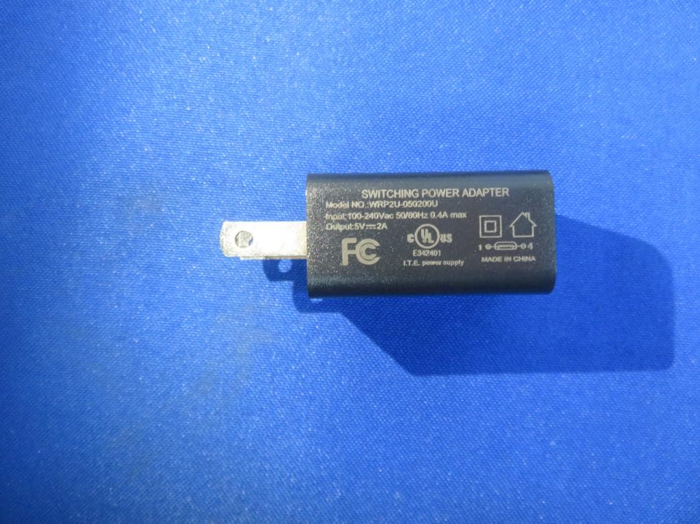
External Photos
FCC ID: 2AVHACV1-03
ID Label/Location Info
Label Location On EUT Label Product Name: NOLO Base Station Model No.: CV1 PRO FCC ID: 2AVHACV1-03
Internal Photos
FCC ID: 2AVHACV1-03 ANT
Operational Description
version01 Beijing Lingyu century Information Technology Co.,Ltd. Declaration concerning Antenna Specification It is hereby declared that the product Model No.: CV1 PRO FCCID:2AVHACV1-03 fulfills the requirement in FCC test relating to the antenna type. The device specified above confirms to the FCC recommendations for internal antenna type(s) described below: Model No. of antenna: N.A. Type of antenna:PCB Antenna Gain of the antenna: 2.46 dBi Frequency range:2402~2475MHz The mounting of the antenna is fixed to the radio module and no other antenna should be used. Company name: Beijing Lingyu century Information Technology Co.,Ltd. Address: Room 101-05, 2f, building 20, yard 1, Baosheng South Road, Haidian District, Beijing, China City: Beijing ZIP / Postal code: Country:China Place:ChinaDate: 2020-02-24 Signature:
RF Exposure Info
RF EXPOSURE EVALUATION EUT Specification EUT NOLO Base Station Model Name CV1 PRO Frequency band (Operating) WLAN: 2.412GHz ~ 2.462GHz WLAN: 5.18GHz ~ 5.32GHz / 5.50GHz ~ 5.70GHz WLAN: 5.745GHz ~ 5825GHz Others: 2402‐2475MHz Device category Portable (<20cm separation) Mobile (>20cm separation) Others ___ Antenna diversity Single antenna Multiple antennas Tx diversity Rx diversity Tx/Rx diversity Max. output power 95.54 dBuV/m (0.2825dBm)(1.068mW) Antenna gain 2.46 dBi Evaluation applied MPE Evaluation SAR Evaluation Standard Requirement Portable Device According to §15.247(i) and §1.1307b(1), systems operating under the provisions of this section shall be operated in a manner that ensures that the public is not exposed to radio frequency energy levels in excess of the Commission’s guidelines. See KDB 447498 D01 General RF Exposure Guidance V6, section 4.3.1. The 1-g and 10-g SAR test exclusion thresholds for 100 MHz to 6 GHz at test separation distances ≤ 50 mm are determined by: [(max. power of channel, including tune-up tolerance, mW)/(min. test separation distance, mm)] ·[√f(GHz)] ≤ 3.0 for 1-g SAR and ≤ 7.5 for 10-g extremity SAR, 16 where ·f(GHz) is the RF channel transmit frequency in GHz ·Power and distance are rounded to the nearest mW and mm before calculation17 ·The result is rounded to one decimal place for comparison The test exclusions are applicable only when the minimum test separation distance is ≤ 50 mm and for transmission frequencies between 100 MHz and 6 GHz. When the minimum test separation distance is < 5 mm, a distance of 5 mm is applied to determine SAR test exclusion. Measurement Result Channel Frequency (MHz) Max Output power (dBm) Tune up tolerance (dBm) Max Tune Up Power (dBm) Distance (mm) Calculati on Value (Note 1) Threshold Value 2441 0.2825 ±1 1.2825 5 0.42 3.0 EIRP=E-104.8+20logD= 95.54 -104.8+20log3= 0.2825dbm Note 1: Calculation Value =[(max. power of channel, included Tune up tolerance, mW)/(min. test separation distance, mm)] ·[√f(GHz)]. Fox example: 1.344/5*√ 2.441=0.42 ≤3.0 According to KDB447498 D01 V6, threshold at which no SAR required is ≤3.0 for 1-g SAR, separation distance is 5mm, and no simultaneous SAR measurement is required. The SAR measurement is not necessary.
Test Report
Report No.: SZAWW191118007-01FCC ID: 2AVHACV1-03Page 1 of 43 Code:AB-RF-05-a FCC TEST REPORT Client Name: Beijing Lingyu century Information Technology Co.,Ltd. Address: Room 101-05, 2f, building 20, yard 1, Baosheng South Road, Haidian District, Beijing, China Product Name: NOLO Base Station Date: Feb. 18, 2020 Shenzhen Anbotek Compliance Laboratory Limited Report No.: SZAWW191118007-01FCC ID: 2AVHACV1-03Page 2 of 43 Code:AB-RF-05-a Contents 1. General Information ............................................................................................................................................... 4 1.1. Client Information ....................................................................................................................................... 4 1.2. Description of Device (EUT) ..................................................................................................................... 4 1.3. Auxiliary Equipment Used During Test ................................................................................................... 5 1.4. Description of Test Modes ........................................................................................................................ 5 1.5. List of Channels .......................................................................................................................................... 6 1.6. Description of Test Setup .......................................................................................................................... 7 1.7. Test Equipment List .................................................................................................................................... 8 1.8. Measurement Uncertainty ......................................................................................................................... 9 1.9. Description of Test Facility ........................................................................................................................ 9 2. Summary of Test Results ................................................................................................................................... 10 3. Conducted Emission Test ................................................................................................................................... 11 3.1. Test Standard and Limit .......................................................................................................................... 11 3.2. Test Setup .................................................................................................................................................. 11 3.3. Test Procedure .......................................................................................................................................... 11 3.4. Test Data .................................................................................................................................................... 12 4. Radiated Emission and Band Edge .................................................................................................................. 15 4.1. Test Standard and Limit .......................................................................................................................... 15 4.2. Test Setup .................................................................................................................................................. 16 4.3. Test Procedure .......................................................................................................................................... 17 4.4. Test Data .................................................................................................................................................... 18 5. 20dB Bandwidth Test .......................................................................................................................................... 28 5.1. Test Standard and Limit .......................................................................................................................... 28 5.2. Test Setup .................................................................................................................................................. 28 5.3. Test Procedure .......................................................................................................................................... 28 5.4. Test Data .................................................................................................................................................... 28 6. Antenna Requirement ......................................................................................................................................... 31 6.1. Test Standard and Requirement ............................................................................................................ 31 6.2. Antenna Connected Construction .......................................................................................................... 31 APPENDIX I -- TEST SETUP PHOTOGRAPH ................................................................................................... 32 APPENDIX II -- EXTERNAL PHOTOGRAPH ..................................................................................................... 34 APPENDIX III -- INTERNAL PHOTOGRAPH ..................................................................................................... 38 Report No.: SZAWW191118007-01FCC ID: 2AVHACV1-03Page 3 of 43 Code:AB-RF-05-a TEST REPORT Applicant: Beijing Lingyu century Information Technology Co.,Ltd. Manufacturer: Beijing Lingyu century Information Technology Co.,Ltd. Product Name: NOLO Base Station Model No.: CV1 PRO Trade Mark: NOLO Rating(s): Input: DC 5V, 1.8A ,9W (DC 3.7V, 1800mAh,6.66Wh Battery inside) Test Standard(s) : FCC Part15 Subpart C, Paragraph 15.249 Test Method(s): ANSI C63.10: 2013 The device described above is tested by Shenzhen Anbot…
Text truncated - open the document above for the full version.
Test Setup Photos
FCC ID: 2AVHACV1-03 Photo of Conducted Emission Test Photo of Radiation Emission Test
Contact Information
Applicant
Kevin Guo(G.M.)
Test Firm
Shenzhen Anbotek Compliance Laboratory LimitedJeff Zhu
Technical Specifications
| # | Rule Parts | Frequency Range | Power Output |
|---|---|---|---|
| 1 | 15C | 2.40 GHz - 2.48 GHz | 1.10 mW |
Other Applications from Beijing Lingyu century Information Technology Co., Ltd.
2AVHACV1-02
Mar 01, 2020NOLO Controller
Equipment Class
DXT - Part 15 Low Power Transceiver, Rx Verified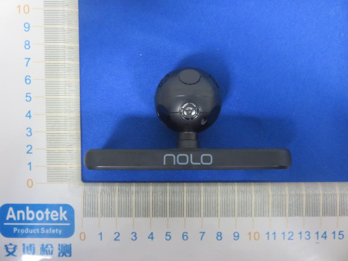
2AVHACV1-PRO
Feb 27, 2020NOLO Headset Marker
Equipment Class
DXT - Part 15 Low Power Transceiver, Rx Verified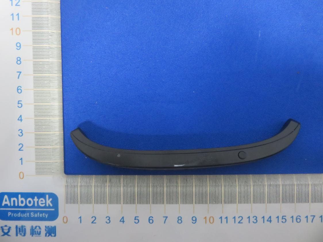
2AVHA-CV1AIR
Feb 27, 2020NOLO Headset Marker
Equipment Class
DXX - Part 15 Low Power Communication Device Transmitter