2AVRVCLT13640114 inch notebook
DP AUDIO VIDEO LLC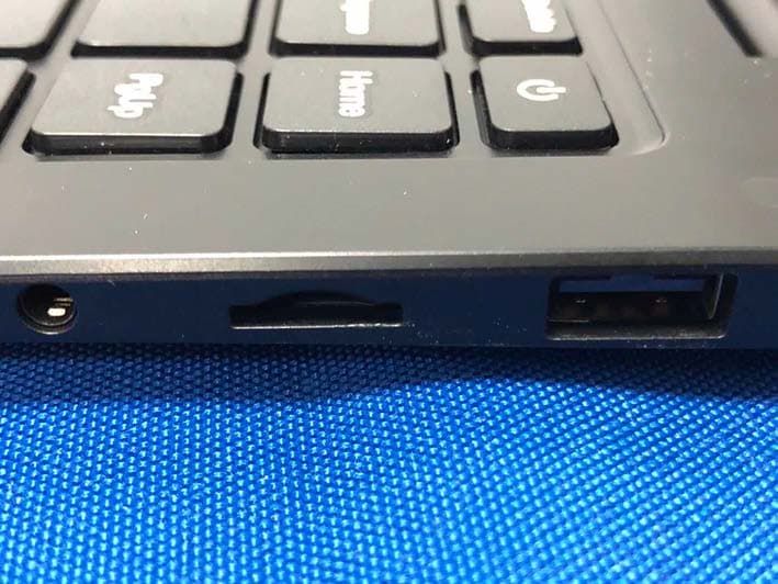
Click to zoom
Application Details
- Equipment Class
- DSS - Part 15 Spread Spectrum Transmitter
- Date of Grant
- Jul 27, 2020
- Application Purpose
- Original Equipment
- Date of Application
- Jul 27, 2020
- Equipment Note
- 14 inch notebook
- Frequency Range
- 2402.00000000 - 2480.00000000
- Company
- DP AUDIO VIDEO LLC
- Country
- United States
Documents & Files
Document Text
Text extracted from the exhibit documents filed with the FCC. Open a document above to read the original.
Users Manual
CORE INNOVATIONS 14" Laptop with Windows™ 10 S CLT136401 User Manual TM 2 1. This laptop works best in non-tropical areas below 6560 feet (2000 meters). 2. Protect your device from impact from bumps and falls. 3. Do not use this device for extended periods of time in environments that are either too cold, too hot, too humid or too dusty. Do not expose the device to direct sunlight. 4. Avoid using this device in strong magnetic and static environments as much as possible. 5. If the device comes into contact with water or any other liquid, power it off immediately and wait for it to dry completely before turning it on again. 6. Do not clean the device with any cleaning products containing chemicals, to avoid damage caused by corrosion and dampness. When cleaning is necessary, use a dry, soft cloth. 7. The company shall not be held responsible for the loss or deletion of material inside the device caused by abnormal software and hardware operation, maintenance or any other accidents. 8. Please regularly back up important data and files to avoid loss. 9. Please do not disassemble the device by yourself; doing so will void the warranty. Read Before Use 3 Unit at a Glance 1. Power Button: Turn your device on or off. Use to set your device to Sleep or to wake it from Sleep. 2. Front Camera: Take photos and videos. 3. Touchpad: Use the touchpad to move your cursor. FRONTTOP BOTTOM LEFTRIGHT 2 5 6 6 1 4 3 14 7 9 8 10 11 12 13 14 4 4. Keyboard: Use the keyboard for typing. 5. Indicators: 1 - The first light from the left indicates that the Power is on. 2 - The middle light indicates that Caps Lock is on. 3 - The third is the Num Lock indicator. When this light is on, you may use the secondary keys on your keyboard. 6. Microphone: Transmits audio signals. 7. Charging Indicator: Red light illuminates when connected to a power adapter. 8. Charging Port: 12V/2A charger. 9. USB 3.0 Port: Provides a faster transfer rate to USB devices. 10. Mini-HDMI Port: Connect your laptop to a monitor or TV. 11. USB 2.0 Port: Connect external USB devices. 12. Headphone Jack: Transmit audio signals to speakers or headphones. 13. Micro SD Card Slot: Built-in memory card reader slot that supports Micro SD format up to 64GB. 14. Speakers: Built-in 2x1W speakers allow you to playback sound without connecting external devices. Unit at a Glance (Continued) Fully charge your laptop for at least six hours before initial use. Use the included wall charger. The battery indicator will confirm that your device is charging. Turn your laptop on by pressing and holding the power key for two seconds. Once the screen is loaded, connect to your Wi-Fi network. To wake the screen from sleep, press the power key and the lock screen should appear. Next, press the upwards arrow key () and log in. Sign in if your laptop requires a password to log in. Getting Started Use your information to create a user account. You can use this account to create, modify or remove other accounts on this device. 5 Windows 10 S Start Menu You will see many applications fixed on the Start menu. These apps are displayed in the form of magnets, allowing you to easily visit programs at the click of a button. You will need to log in to your Microsoft account before the applications can fully run. Learn more about Windows 10 S at: https:/ /www.microsoft.com/en-us/windows/s-mode Interface Introduction 6 Microsoft-Verified Security With Windows 10 in S mode, your favorite applications, such as Office, Evernote and Spotify are available from the Microsoft Store where they’re Microsoft-verified for security. Feel secure when you’re online. Microsoft Edge, your default browser, gives you more protection against phishing and socially-engineered malware than Chrome or Firefox. Switching out of S Mode Windows 10 in S mode is designed for security and performance, exclusively running apps from the Microsoft Store. If you want to install an app that isn’t available in the Microsoft Store, you’ll need to switch out of S mode. Note: Switching out of S mode is one-way. If you make the switch, you won’t be able to go back to Windows 10 in S mode. You may switch back only if a software upgrade is made available. We recommend that you back up all your files onto an external hard drive before switching OS. Switching out of S mode is free of charge. To switch out of S Mode, follow these steps: 1. Make sure you are logged into the Microsoft Store. Windows 10 in S Mode 7 2. In the Microsoft Store, search for “Switch out of S Mode.” 3. Click on the Get button. Once the software has downloaded, click on the Install button and follow the onscreen instructions to complete the setup. Windows 10 in S Mode (Continued) 8 In addition to the applications already fixed on the Start Menu, all other apps can be accessed from your laptop’s homepage. To add multiple apps to the Start Menu: 1. Right click on the app icon you wish to pin to the Start Menu 2. Select Pin to Start Conversely, if you want to remove an app from the Start Menu: 1. Right click on the app icon 2. Select Unpin from Start Applications Introduction 9 The Menu bar is located within your Windows Start Menu, found at the bottom of your screen. PC: Allows you to set up, lock and sign out Documents: Opens the Documents folder in your laptop Pictures: Opens the Pictures folder in your laptop Settings: Setup and customize your device Power: Sleep, shutdown or restart your device Menu Bar You can download more apps from the Microsoft Store found on the Windows Start Menu. Note: You need a Microsoft account to be able to download apps. You can create an account by logging on to https://account.microsoft.com/account Once you’ve created an account, go to the Microsoft Store app on your laptop and sign in by clicking the icon. Downloading Apps 10 You can see notifications on the Action Center. The Search Bar can be found in your Start Menu. Use it to find documents or files stored in your device. You can also use the Search Bar to search fo…
Text truncated - open the document above for the full version.
Attestation Statements
DP AUDIO VIDEO LLC Date: 2020-07-18 To: Federal Communications Commission FCC ID: 2AVRVCLT136401 To Whom It May Concern: This letter is to ascertain that DP AUDIO VIDEO LLC MODEL No.: CLT136401CLT136401BL, CLT136401SL, CLT136401BU, CLT136401PN,CLT136401PR, CLT136401TL, CLT136401RD Has been the units used for conducting FCC compliance testing, the SDoC part will be tested by Shenzhen BCTC Testing Co., Ltd. If you have any question or concerns, pls. contact us. Sincerely, Client’s signature : Client’s name / title : Roy Ryan (Manager) Contact information / address: DP AUDIO VIDEO LLC
Cover Letter(s)
DP AUDIO VIDEO LLC Model Difference 2020-07-18 EUT NAME: 14 inch notebook FCC ID: FCC: 2AVRVCLT136401 MODEL : CLT136401 CLT136401PR, CLT136401TL, CLT136401RD All the model are the same circuit and RF module, except model names. Regards Sincerely Client’s signature Client’s name / title : Roy Ryan (Manager) Contact information / address: 10660 WILSHIRE BLVD LOS ANGELES, California United States 90024 CLT136401BL, CLT136401SL, CLT136401BU, CLT136401PN,
Cover Letter(s)
(DP AUDIO VIDEO LLC) Federal Communications Commission Authorization and Evaluation Division 1435 Oakland Mills Road Columbia, MD 21046 Date: 2020.7.18 SUBJECT: FCC Application for FCC ID: 2AVRVCLT136401 To Whom It May Concern: We, the undersigned, hereby authorize Alan Mei at Shenzhen BCTC Testing Co., Ltd. on our behalf, to apply to the Federal Communications Commission on our equipment. Any and all acts carried out by Alan Mei of Shenzhen BCTC Testing Co., Ltd. on our behalf shall have the same effect as acts of our own. This is to advise that we are in full compliance with the Anti- Drug Abuse Act. We, the applicant, are not subject to a denial of federal benefits pursuant to Section 5301 of the Anti-Drug Act of 1988, 21 USC853a, and no party to the application is subject to a denial of federal benefits pursuant to that section. Regards, (Roy Ryan)
External Photos
External Photos
ID Label/Location Info
Label & label location
Internal Photos
Internal Photos Antenna
RF Exposure Info
RF EXPOSURE EVALUATION METHOD FCC ID: 2AVRVCLT136401 SAR Test Exclusion Thresholds for 100 MHz – 6 GHz and ≤ 50 mm Approximate SAR Test Exclusion Power Thresholds at Selected Frequencies and Test Separation Distances are illustrated in the following Table. The 1-g and 10-g SAR test exclusion thresholds for 100 MHz to 6 GHz at test separation distances ≤ 50 mm are determined by: [(max. power of channel, including tune-up tolerance, mW)/(min. test separation distance, mm)] · [√f(GHz)] ≤ 3.0 for 1-g SAR and ≤ 7.5 for 10-g extremity SAR,where f(GHz) is the RF channel transmit frequency in GHz Power and distance are rounded to the nearest mW and mm before calculation The result is rounded to one decimal place for comparison The test exclusions are applicable only when the minimum test separation distance is ≤ 50 mm and for transmission frequencies between 100 MHz and 6 GHz. When the minimum test separation distance is < 5 mm, a distance of 5 mm is applied to determine SAR test exclusion. BT-EDR max possible output power (PK,conducted):0±1dbm 1dBi logarithmic terms convert to numeric result is nearly 1.259 1dBm=1.26mW 2402MHz [(max. power of channel, including tune-up tolerance, mW)/(min. test separation distance,mm)] · [√f(GHz)]=1.26/5*√2.402=0.39≤3.0 Threshold at which no SAR required is 10mw and ≤ 3.0 for 1-g SAR, Separation distance is 5mm. Modulation Frequency (MHz) Output Power (dBm) Max Antenna Gain (dBi) GFSK Low 1.040 1 GFSK Middle 1.040 1 GFSK High 0.916 1 Pi/4 DQPSK Low 1.361 1 Pi/4 DQPSK Middle 1.360 1 Pi/4 DQPSK High 1.247 1 8DPSK Low 1.300 1 8DPSK Middle 1.302 1 8DPSK High 1.216 1 2441MHz [(max. power of channel, including tune-up tolerance, mW)/(min. test separation distance,mm)] · [√f(GHz)]= 1.26/5*√2.441 =0.39≤3.0 Threshold at which no SAR required is 10mw and ≤ 3.0 for 1-g SAR, Separation distance is 5mm. 2480MHz [(max. power of channel, including tune-up tolerance, mW)/(min. test separation distance,mm)] · [√f(GHz)]=1.26/5*√2.48=0.40≤3.0 Threshold at which no SAR required is 10mw and ≤ 3.0 for 1-g SAR, Separation distance is 5mm. BT-BLE max possible output power (PK,conducted):1±1dbm 1dBi logarithmic terms convert to numeric result is nearly 1.259 2dBm=1.58mW 2402MHz [(max. power of channel, including tune-up tolerance, mW)/(min. test separation distance,mm)] · [√f(GHz)]=1.58/5*√2.402=0.49≤3.0 Threshold at which no SAR required is 10mw and ≤ 3.0 for 1-g SAR, Separation distance is 5mm. Modulation Frequency (MHz) Output Power (dBm) Max Antenna Gain (dBi) GFSK 2402 1.10 1 GFSK 2440 1.02 1 GFSK 2480 0.37 1 2440MHz [(max. power of channel, including tune-up tolerance, mW)/(min. test separation distance,mm)] · [√f(GHz)]= 1.58/5*√2.44=0.50≤3.0 Threshold at which no SAR required is 10mw and ≤ 3.0 for 1-g SAR, Separation distance is 5mm. 2480MHz [(max. power of channel, including tune-up tolerance, mW)/(min. test separation distance,mm)] · [√f(GHz)]=1.58/5*√2.48=0.50≤3.0 Threshold at which no SAR required is 10mw and ≤ 3.0 for 1-g SAR, Separation distance is 5mm. WIFI Frequency Maximum Conducted Output Power(PK) LIMIT (MHz) (dBm) dBm 802.11b 2412 8.34 30 2437 8.94 30 2462 8.88 30 802.11g 2412 7.06 30 2437 7.60 30 2462 7.25 30 802.11n20 2412 7.93 30 2437 7.42 30 2462 7.03 30 802.11n40 2422 7.31 30 2437 7.23 30 2452 7.54 30 max possible output power (PK,conducted):8.5±1dbm 1dBi logarithmic terms convert to numeric result is nearly 1.259 9.5dbm=8.91mW 2412MHz [(max. power of channel, including tune-up tolerance, mW)/(min. test separation distance,mm)] · [√f(GHz)]=8.91/5*√2.412=2.77≤3.0 Threshold at which no SAR required is 10mw and ≤ 3.0 for 1-g SAR, Separation distance is 5mm. 2437MHz [(max. power of channel, including tune-up tolerance, mW)/(min. test separation distance,mm)] · [√f(GHz)]= 8.91/5*√2.437=2.78≤3.0 Threshold at which no SAR required is 10mw and ≤ 3.0 for 1-g SAR, Separation distance is 5mm. 2462 MHz [(max. power of channel, including tune-up tolerance, mW)/(min. test separation distance,mm)] · [√f(GHz)]=8.91/5*√2.462=2.80≤3.0 Threshold at which no SAR required is 10mw and ≤ 3.0 for 1-g SAR, Separation distance is 5mm. Conclusion: No SAR is required.
Test Report
Shenzhen BCTC Testing Co., Ltd. Report No.: BCTC2006001390-1E FCC Part 15C Test Report FCC ID: 2AVRVCLT136401 Product Name: 14 inch notebook Trademark: CORE INNOVATIONS Model Name : CLT136401 CLT136401BL, CLT136401SL, CLT136401BU, CLT136401PN, CLT136401PR, CLT136401TL, CLT136401RD Prepared For : DP AUDIO VIDEO LLC Address : 920 Malcolm Ave Los Angeles, California, USA 90024 Prepared By : Shenzhen BCTC Testing Co., Ltd. Address : BCTC Building & 1-2F, East of B Building, Pengzhou Industrial, Fuyuan 1st Road, Qiaotou Community, Fuyong Street, Bao’an District, Shenzhen, China Test Date: Jun. 17, 2020 – Jun. 30, 2020 Date of Report : Jun. 30, 2020 Report No.: BCTC2006001390-1E Te s t Report Tel: 400-788-9558 Web: https://www.bctc-lab.com BCTC/RF-EMC-0 07 Ver.:A.0 Page 1 of 69 Shenzhen BCTC Testing Co., Ltd. Report No.: BCTC2006001390-1E TEST RESULT CERTIFICATION Applicant’s name ............. : DP AUDIO VIDEO LLC Address .............................. : 920 Malcolm Ave Los Angeles, California, USA 90024 Manufacture's Name ........ : Shenzhen KeJinMing Electronic CO., Limited Address .............................. : Floor1-6, BlockB7, Yintian Industrial Park, Yantian Community, XixiangStreet, Bao'an Dist., Shenzhen, China Product description Product name .................... : 14 inch notebook Trademark ......................... : CORE INNOVATIONS Model and/or type reference CLT136401 CLT136401BL, CLT136401SL, CLT136401BU, CLT136401PN, CLT136401PR, CLT136401TL, CLT136401RD Standards ......................... : FCC Part15.247 ANSI C63.10:2013 This device described above has been tested by BCTC, and the test results show that the equipment under test (EUT) is in compliance with the FCC requirements. And it is applicable only to the tested sample identified in the report. This report shall not be reproduced except in full, without the written approval of BCTC, this document may be altered or revised by BCTC, personal only, and shall be noted in the revision of the document. Prepared by(Engineer): Sam zeng Reviewer(Supervisor): Eric Yang Approved(Manager): Zero Zhou Te s t Report Tel: 400-788-9558 Web: https://www.bctc-lab.com BCTC/RF-EMC-0 07 Ver.:A.0 Page 2 of 69 Shenzhen BCTC Testing Co., Ltd. Report No.: BCTC2006001390-1E Table of Contents Test Report Declaration Page 1. TEST SUMMARY .............................................................................................. 5 2. TEST FACILITY ................................................................................................ 6 3. MEASUREMENT UNCERTAINTY .................................................................... 6 4. GENERAL INFORMATION ............................................................................... 7 4.1 GENERAL DESCRIPTION OF EUT ..................................................................... 7 4.2 Test Setup Configuration ...................................................................................... 8 4.3 Support Equipment ............................................................................................... 8 4.4 Channel List .......................................................................................................... 9 4.5 Test Mode ........................................................................................................... 10 5. TEST FACILITY AND TEST INSTRUMENT USED...........................................11 5.1 Test Facility ......................................................................................................... 11 5.2 Test Instrument Used ......................................................................................... 11 6. CONDUCTED EMISSIONS ..............................................................................13 6.1 Block Diagram Of Test Setup ............................................................................. 13 6.2 Limit .................................................................................................................... 13 6.3 Test procedure .................................................................................................... 13 6.4 Test Result.......................................................................................................... 15 7. RADIATED EMISSIONS ..................................................................................17 7.1 Block Diagram Of Test Setup ............................................................................. 17 7.2 Limit .................................................................................................................... 18 7.3 Test procedure .................................................................................................... 18 7.4 Test Result.......................................................................................................... 20 7.5 RADIATED BAND EMISSION MEASUREMENT AND RESTRICTED BANDS OF OPERATION ......................................................................................................... 24 8. CONDUCTED EMISSION ................................................................................27 8.1 Block Diagram Of Test Setup ............................................................................. 27 8.2 Limit .................................................................................................................... 27 8.3 Test procedure .................................................................................................... 27 8.4 Test Result.......................................................................................................... 28 9. 20 DB BANDWIDTH ........................................................................................37 9.1 Block Diagram Of Test Setup ............................................................................. 37 Te s t Report Tel: 400-788-9558 Web: https://www.bctc-lab.com BCTC/RF-EMC-0 07 Ver.:A.0 Page 3 of 69 Shenzhen BCTC Testing Co., Ltd. Report No.: B…
Text truncated - open the document above for the full version.
Test Report
Shenzhen BCTC Testing Co., Ltd. Report No.: BCTC2006001390-1E GFSK Transmitting Band edge-right side GFSK Hopping Band edge-right side Te s t Report Tel: 400-788-9558 Web: https://www.bctc-lab.com BCTC/RF-EMC-0 07 Ver.:A.0 Page 32 of 69 Shenzhen BCTC Testing Co., Ltd. Report No.: BCTC2006001390-1E Pi/4 DQPSK Transmitting Band edge-left side Pi/4 DQPSK Hopping Band edge-left side Te s t Report Tel: 400-788-9558 Web: https://www.bctc-lab.com BCTC/RF-EMC-0 07 Ver.:A.0 Page 33 of 69 Shenzhen BCTC Testing Co., Ltd. Report No.: BCTC2006001390-1E Pi/4 DQPSK Transmitting Band edge-right side Pi/4 DQPSK Hopping Band edge-right side Te s t Report Tel: 400-788-9558 Web: https://www.bctc-lab.com BCTC/RF-EMC-0 07 Ver.:A.0 Page 34 of 69 Shenzhen BCTC Testing Co., Ltd. Report No.: BCTC2006001390-1E 8DPSK Transmitting Band edge-left side 8DPSK Hopping Band edge-left side Te s t Report Tel: 400-788-9558 Web: https://www.bctc-lab.com BCTC/RF-EMC-0 07 Ver.:A.0 Page 35 of 69 Shenzhen BCTC Testing Co., Ltd. Report No.: BCTC2006001390-1E 8DPSK Transmitting Band edge-right side 8DPSK Hopping Band edge-right side Te s t Report Tel: 400-788-9558 Web: https://www.bctc-lab.com BCTC/RF-EMC-0 07 Ver.:A.0 Page 36 of 69 Shenzhen BCTC Testing Co., Ltd. Report No.: BCTC2006001390-1E 9. 20 DB BANDWIDTH 9.1 Block Diagram Of Test Setup 9.2 Limit N/A 9.3 Test procedure 1. Set RBW = 30 kHz. 2. Set the video bandwidth (VBW) ≥ 3 x RBW. 3. Detector = Peak. 4. Trace mode = max hold. 5. Sweep = auto couple. 6. Allow the trace to stabilize. 7. Measure the maximum width of the emission that is constrained by the frequencies associated with the two outermost amplitude points (upper and lower frequencies) that are attenuated by 20 dB relative to the maximum level measured in the fundamental emission. EUT Radio Test System Te s t Report Tel: 400-788-9558 Web: https://www.bctc-lab.com BCTC/RF-EMC-0 07 Ver.:A.0 Page 37 of 69 Shenzhen BCTC Testing Co., Ltd. Report No.: BCTC2006001390-1E 9.4 Test Result Modulation Test Channel Bandwidth(MHz) GFSK Low 1.040 GFSK Middle 1.040 GFSK High 0.916 Pi/4 DQPSK Low 1.361 Pi/4 DQPSK Middle 1.360 Pi/4 DQPSK High 1.247 8DPSK Low 1.300 8DPSK Middle 1.302 8DPSK High 1.216 Test plots GFSK Low Channel Te s t Report Tel: 400-788-9558 Web: https://www.bctc-lab.com BCTC/RF-EMC-0 07 Ver.:A.0 Page 38 of 69 Shenzhen BCTC Testing Co., Ltd. Report No.: BCTC2006001390-1E GFSK Middle Channel GFSK High Channel Te s t Report Tel: 400-788-9558 Web: https://www.bctc-lab.com BCTC/RF-EMC-0 07 Ver.:A.0 Page 39 of 69 Shenzhen BCTC Testing Co., Ltd. Report No.: BCTC2006001390-1E Pi/4 DQPSK Low Channel Pi/4 DQPSK Middle Channel Te s t Report Tel: 400-788-9558 Web: https://www.bctc-lab.com BCTC/RF-EMC-0 07 Ver.:A.0 Page 40 of 69 Shenzhen BCTC Testing Co., Ltd. Report No.: BCTC2006001390-1E Pi/4 DQPSK High Channel 8DPSK Low Channel Te s t Report Tel: 400-788-9558 Web: https://www.bctc-lab.com BCTC/RF-EMC-0 07 Ver.:A.0 Page 41 of 69 Shenzhen BCTC Testing Co., Ltd. Report No.: BCTC2006001390-1E 8DPSK Middle Channel 8DPSK High Channel Te s t Report Tel: 400-788-9558 Web: https://www.bctc-lab.com BCTC/RF-EMC-0 07 Ver.:A.0 Page 42 of 69 Shenzhen BCTC Testing Co., Ltd. Report No.: BCTC2006001390-1E 10. MAXIMUM PEAK OUTPUT POWER 10.1 Block Diagram Of Test Setup 10.2 Limit For frequency hopping systems operating in the 2400-2483.5 MHz band employing at least 75 non-overlapping hopping channels, and all frequency hopping systems in the 5725-5850 MHz band: 1 watt. For all other frequency hopping systems in the 2400-2483.5 MHz band: 0.125 watts. 10.3 Test procedure 1. Remove the antenna from the EUT and then connect a low RF cable from the antenna port to the spectrum. 2. Set the spectrum analyzer: RBW = 3MHz. VBW = 3MHz. Sweep = auto; Detector Function = Peak. 3. Keep the EUT in transmitting at lowest, medium and highest channel individually. Record the max value. EUT Radio Test System Te s t Report Tel: 400-788-9558 Web: https://www.bctc-lab.com BCTC/RF-EMC-0 07 Ver.:A.0 Page 43 of 69 Shenzhen BCTC Testing Co., Ltd. Report No.: BCTC2006001390-1E 10.4 Test Result Modulation Test Channel Output Power (dBm) Limit (dBm) GFSK Low 3.81 21 GFSK Middle 3.91 21 GFSK High 3.29 21 Pi/4 DQPSK Low 4.89 21 Pi/4 DQPSK Middle 4.88 21 Pi/4 DQPSK High 4.24 21 8DPSK Low 5.03 21 8DPSK Middle 5.05 21 8DPSK High 4.43 21 Test plots GFSK Low Channel Te s t Report Tel: 400-788-9558 Web: https://www.bctc-lab.com BCTC/RF-EMC-0 07 Ver.:A.0 Page 44 of 69 Shenzhen BCTC Testing Co., Ltd. Report No.: BCTC2006001390-1E GFSK Middle Channel GFSK High Channel Te s t Report Tel: 400-788-9558 Web: https://www.bctc-lab.com BCTC/RF-EMC-0 07 Ver.:A.0 Page 45 of 69 Shenzhen BCTC Testing Co., Ltd. Report No.: BCTC2006001390-1E Pi/4 DQPSK Low Channel Pi/4 DQPSK Middle Channel Te s t Report Tel: 400-788-9558 Web: https://www.bctc-lab.com BCTC/RF-EMC-0 07 Ver.:A.0 Page 46 of 69 Shenzhen BCTC Testing Co., Ltd. Report No.: BCTC2006001390-1E Pi/4 DQPSK High Channel 8DPSK Low Channel Te s t Report Tel: 400-788-9558 Web: https://www.bctc-lab.com BCTC/RF-EMC-0 07 Ver.:A.0 Page 47 of 69 Shenzhen BCTC Testing Co., Ltd. Report No.: BCTC2006001390-1E 8DPSK Middle Channel 8DPSK High Channel Te s t Report Tel: 400-788-9558 Web: https://www.bctc-lab.com BCTC/RF-EMC-0 07 Ver.:A.0 Page 48 of 69 Shenzhen BCTC Testing Co., Ltd. Report No.: BCTC2006001390-1E 11. HOPPING CHANNEL SEPARATION 11.1 Block Diagram Of Test Setup 11.2 Limit Frequency hopping systems shall have hopping channel carrier frequencies separated by a minimum of 25 kHz or the 20 dB bandwidth of the hopping channel, whichever is greater. Alternatively, frequency hopping systems operating in the 2400-2483.5 MHz band may have hopping channel carrier frequencies that are separated by 25 kHz or two-thirds of the 20 dB bandwidth of the hopping channel, whichever is greater, provided the systems operate with an output power no greater than 0.125W. 11.3 Test procedure 1. Remove the antenna from the EUT and then connect a low RF cable from t…
Text truncated - open the document above for the full version.
Test Report
Shenzhen BCTC Testing Co., Ltd. Report No.: BCTC2006001390-1E 12.4 Test Result Test Plots: 79 Channels in total GFSK Pi/4 DQPSK Te s t Report Tel: 400-788-9558 Web: https://www.bctc-lab.com BCTC/RF-EMC-0 07 Ver.:A.0 Page 56 of 69 Shenzhen BCTC Testing Co., Ltd. Report No.: BCTC2006001390-1E 8DPSK Te s t Report Tel: 400-788-9558 Web: https://www.bctc-lab.com BCTC/RF-EMC-0 07 Ver.:A.0 Page 57 of 69 Shenzhen BCTC Testing Co., Ltd. Report No.: BCTC2006001390-1E 13. DWELL TIME 13.1 Block Diagram Of Test Setup 13.2 Limit Frequency hopping systems in the 2400-2483.5 MHz band shall use at least 15 channels. The average time of occupancy on any channel shall not be greater than 0.4 seconds within a period of 0.4 seconds multiplied by the number of hopping channels employed. Frequency hopping systems may avoid or suppress transmissions on a particular hopping frequency provided that a minimum of 15 channels are used. 13.3 Test procedure 1. Remove the antenna from the EUT and then connect a low RF cable from the antenna port to the spectrum. 2. Set spectrum analyzer span = 0. Centred on a hopping channel; 3. Set RBW = 1MHz and VBW = 3MHz.Sweep = as necessary to capture the entire dwell time per hopping channel. Set the EUT for DH5, DH3 and DH1 packet transmitting. 4. Use the marker-delta function to determine the dwell time. If this value varies with different modes of operation (e.g.. data rate. modulation format. etc.). repeat this test for each variation. The limit is specified in one of the subparagraphs of this Section. Submit this plot(s). EUT Radio Test System Te s t Report Tel: 400-788-9558 Web: https://www.bctc-lab.com BCTC/RF-EMC-0 07 Ver.:A.0 Page 58 of 69 Shenzhen BCTC Testing Co., Ltd. Report No.: BCTC2006001390-1E 13.4 Test Result DH5 Packet permit maximum 1600 / 79 / 6 hops per second in each channel (5 time slots RX, 1 time slot TX). DH3 Packet permit maximum 1600 / 79 / 4 hops per second in each channel (3 time slots RX, 1 time slot TX). DH1 Packet permit maximum 1600 / 79 /2 hops per second in each channel (1 time slot RX, 1 time slot TX). So, the Dwell Time can be calculated as follows: DH5:1600/79/6*0.4*79*(MkrDelta)/1000 DH3:1600/79/4*0.4*79*(MkrDelta)/1000 DH1:1600/79/2*0.4*79*(MkrDelta)/1000 Remark: Mkr Delta is once pulse time. Modulation Channel Data Packet pulse time(ms) Dwell Time(s) Limits(s) GFSK Middle DH1 0.412 0.132 0.4 DH3 1.680 0.269 0.4 DH5 2.930 0.313 0.4 Pi/4DQPSK Middle 2DH1 0.420 0.134 0.4 2DH3 1.686 0.270 0.4 2DH5 2.940 0.314 0.4 8DPSK Middle 3DH1 0.421 0.135 0.4 3DH3 1.680 0.269 0.4 3DH5 2.940 0.314 0.4 Te s t Report Tel: 400-788-9558 Web: https://www.bctc-lab.com BCTC/RF-EMC-0 07 Ver.:A.0 Page 59 of 69 Shenzhen BCTC Testing Co., Ltd. Report No.: BCTC2006001390-1E Test Plots GFSK DH1 Middle Channel GFSK DH3 Middle Channel Te s t Report Tel: 400-788-9558 Web: https://www.bctc-lab.com BCTC/RF-EMC-0 07 Ver.:A.0 Page 60 of 69 Shenzhen BCTC Testing Co., Ltd. Report No.: BCTC2006001390-1E GFSK DH5 High Middle Channel Pi/4DQPSK DH1 Middle Channel Te s t Report Tel: 400-788-9558 Web: https://www.bctc-lab.com BCTC/RF-EMC-0 07 Ver.:A.0 Page 61 of 69 Shenzhen BCTC Testing Co., Ltd. Report No.: BCTC2006001390-1E Pi/4DQPSK DH3 Middle Channel Pi/4DQPSK DH5 Middle Channel Te s t Report Tel: 400-788-9558 Web: https://www.bctc-lab.com BCTC/RF-EMC-0 07 Ver.:A.0 Page 62 of 69 Shenzhen BCTC Testing Co., Ltd. Report No.: BCTC2006001390-1E 8DPSK DH1 Middle Channel 8DPSK DH3 Middle Channel Te s t Report Tel: 400-788-9558 Web: https://www.bctc-lab.com BCTC/RF-EMC-0 07 Ver.:A.0 Page 63 of 69 Shenzhen BCTC Testing Co., Ltd. Report No.: BCTC2006001390-1E 8DPSK DH5 Middle Channel Te s t Report Tel: 400-788-9558 Web: https://www.bctc-lab.com BCTC/RF-EMC-0 07 Ver.:A.0 Page 64 of 69 Shenzhen BCTC Testing Co., Ltd. Report No.: BCTC2006001390-1E 14. ANTENNA REQUIREMENT An intentional radiator shall be designed to ensure that no antenna other than that furnished by the responsible party shall be used with the device. The use of a permanently attached antenna or of an antenna that uses a unique coupling to the intentional radiator shall be considered sufficient to comply with the provisions of this section. The manufacturer may design the unit so that a broken antenna can be replaced by the user, but the use of a standard antenna jack or electrical connector is prohibited. This requirement does not apply to carrier current devices or to devices operated under the provisions of §15.211, §15.213, §15.217, §15.219, or §15.221. Further, this requirement does not apply to intentional radiators that must be professionally installed, such as perimeter protection systems and some field disturbance sensors, or to other intentional radiators which, in accordance with §15.31(d), must be measured at the installation site. However, the installer shall be responsible for ensuring that the proper antenna is employed so that the limits in this part are not exceeded. For intentional device, according to FCC 47 CFR Section 15.203, an intentional radiator shall be designed to ensure that no antenna other than that furnished by the responsible party shall be used with the device. The EUT antenna is FPCB antenna, antenna Gain 1dBi. It comply with the standard requirement. Te s t Report Tel: 400-788-9558 Web: https://www.bctc-lab.com BCTC/RF-EMC-0 07 Ver.:A.0 Page 65 of 69 Shenzhen BCTC Testing Co., Ltd. Report No.: BCTC2006001390-1E 15. EUT PHOTOGRAPHS EUT Photo 1 EUT Photo 2 Te s t Report Tel: 400-788-9558 Web: https://www.bctc-lab.com BCTC/RF-EMC-0 07 Ver.:A.0 Page 66 of 69 Shenzhen BCTC Testing Co., Ltd. Report No.: BCTC2006001390-1E EUT Photo 3 EUT Photo 4 Te s t Report Tel: 400-788-9558 Web: https://www.bctc-lab.com BCTC/RF-EMC-0 07 Ver.:A.0 Page 67 of 69 Shenzhen BCTC Testing Co., Ltd. Report No.: BCTC2006001390-1E 16. EUT TEST SETUP PHOTOGRAPHS Conducted Measurement Photos Te s t Report Tel: 400-788-…
Text truncated - open the document above for the full version.
Contact Information
Applicant
Roy Ryan
Test Firm
Shenzhen BCTC Testing Co., Ltd.Alan Mei
[email protected]+8675536882589
Technical Specifications
| # | Rule Parts | Frequency Range | Power Output |
|---|---|---|---|
| 1 | 15C | 2.40 GHz - 2.48 GHz | 3.20 mW |
Other Applications from DP AUDIO VIDEO LLC
2AVRVBS500HT
Sep 10, 2024Hot Tub & Pool Bluetooth Floating Speaker
Equipment Class
DSS - Part 15 Spread Spectrum Transmitter
2AVRV-DG3200
Jul 21, 202432inch Rollable Smart Touchscreen TV
Equipment Class
DTS - Digital Transmission System
2AVRVKRMIC200
Jul 10, 2024Portable Karaoke Machine
Equipment Class
DSS - Part 15 Spread Spectrum Transmitter
2AVRVCC2400
Jan 16, 2024AIO computer
Equipment Class
DTS - Digital Transmission System
2AVRVCTP100LG
Jan 08, 2024Professional Wireless Thermal Printer
Equipment Class
DSS - Part 15 Spread Spectrum Transmitter