2AVRVCLT136401V314 inch notebook
DP AUDIO VIDEO LLC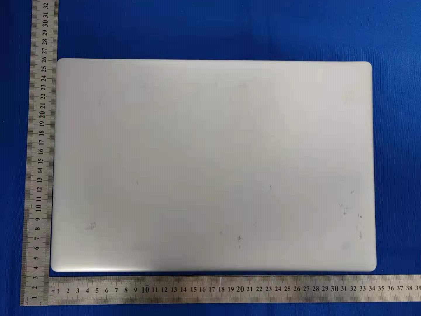
Click to zoom
Application Details
- Equipment Class
- DTS - Digital Transmission System
- Date of Grant
- Apr 27, 2021
- Application Purpose
- Original Equipment
- Date of Application
- Apr 27, 2021
- Equipment Note
- 14 inch notebook
- Frequency Range
- 2412.00000000 - 2462.00000000
- Company
- DP AUDIO VIDEO LLC
- Country
- United States
Documents & Files
Document Text
Text extracted from the exhibit documents filed with the FCC. Open a document above to read the original.
Users Manual
CORE INNOVATIONS 14" Laptop with Windows™ 10 S CLT136401 User Manual TM 1 1. This laptop works best in non-tropical areas below 6560 feet (2000 meters). 2. Protect your device from impact from bumps and falls. 3. Do not use this device for extended periods of time in environments that are either too cold, too hot, too humid or too dusty. Do not expose the device to direct sunlight. 4. Avoid using this device in strong magnetic and static environments as much as possible. 5. If the device comes into contact with water or any other liquid, power it off immediately and wait for it to dry completely before turning it on again. 6. Do not clean the device with any cleaning products containing chemicals, to avoid damage caused by corrosion and dampness. When cleaning is necessary, use a dry, soft cloth. 7. The company shall not be held responsible for the loss or deletion of material inside the device caused by abnormal software and hardware operation, maintenance or any other accidents. 8. Please regularly back up important data and files to avoid loss. 9. Please do not disassemble the device by yourself; doing so will void the warranty. Read Before Use 2 1. Power Button Sleep or to wake it from Sleep. 2. Fr ont Camera: T ake photos and videos. 3. Touchpad: Use the touchpad to move your cursor. Unit at a Glance FRONTTOP LEFTRIGHT 2 5 6 6 1 4 3 7 9 8 10 11 13 12 BOTTOM 1414 3 4. Keyboard: Use the keyboard for typing. 5. Indicators: 1 - The first light from the left indicates that the Power is on. 2 - The middle light indicates that Caps Lock is on. 3 - The third is the Num Lock indicator. When this light is on, you may use the secondary keys on your keyboard. 6. Microphone: Transmits audio signals. 7. Charging Indicator: Red light illuminates when connected to a power adapter. 8. Charging Port: 5V/3A charger. 9. USB Input: Connect external USB devices. 10. Mini HDMI ® Output: Connect your laptop to a monitor, TV or other HDMI ® -enabled device. 11. USB Input: Connect external USB devices. 12. Headphone Jack: Transmit audio signals to speakers or headphones. 13. Micro SD Card Slot: Built-in memory card reader slot that supports Micro SD format up to 64GB. 14. Speakers: Built-in 2x1W speakers allow you to playback sound without connecting external devices. Unit at a Glance (Continued) Fully charge your laptop for at least six hours before initial use. Use the included wall charger. The battery indicator will confirm that your device is charging. Turn your laptop on by pressing and holding the power key for two seconds. Once the screen is loaded, connect to your Wi-Fi ® network. To wake the screen from sleep, press the power key and the lock screen should appear. Next, press the upwards arrow key () and log in. Sign in if your laptop requires a password to log in. Getting Started Use your information to create a user account. You can use this account to create, modify or remove other accounts on this device. 4 Windows™ 10 S Start Menu You will see many applications fixed on the Start menu. These apps are displayed in the form of magnets, allowing you to easily visit programs at the click of a button. You will need to log in to your Microsoft™ account before the applications can fully run. Learn more about Windows™ 10 S at: https:/ /www.microsoft.com/en-us/windows/s-mode Interface Introduction 5 Microsoft™-Verified Security With Windows™ 10 in S mode, your favorite applications, such as Office, Evernote and Spotify are available from the Microsoft™ Store where they’re Microsoft™-verified for security. Feel secure when you’re online. Microsoft Edge™, your default browser, gives you more protection against phishing and socially-engineered malware than Chrome or Firefox. Switching out of S Mode Windows™ 10 in S mode is designed for security and performance, exclusively running apps from the Microsoft™ Store. If you want to install an app that isn’t available in the Microsoft™ Store, you’ll need to switch out of S mode. Note: Switching out of S mode is one-way. If you make the switch, you won’t be able to go back to Windows™ 10 in S mode. You may switch back only if a software upgrade is made available. We recommend that you back up all your files onto an external hard drive before switching OS. Switching out of S mode is free of charge. To switch out of S Mode, follow these steps: 1. Make sure you are logged into the Microsoft™ Store. Windows™ 10 in S Mode 6 2. In the Microsoft™ Store, search for “Switch out of S Mode.” 3. Click on the Get button. Once the software has downloaded, click on the Install button and follow the onscreen instructions to complete the setup. Windows™ 10 in S Mode (Continued) 7 In addition to the applications already fixed on the Start Menu, all other apps can be accessed from your laptop’s homepage. To add multiple apps to the Start Menu: 1. Right click on the app icon you wish to pin to the Start Menu 2. Select Pin to Start Conversely, if you want to remove an app from the Start Menu: 1. Right click on the app icon 2. Select Unpin from Start Applications Introduction 8 The Menu bar is located within your Windows™ Start Menu, found at the bottom of your screen. PC: Allows you to set up, lock and sign out Documents: Opens the Documents folder in your laptop Pictures: Opens the Pictures folder in your laptop Settings: Setup and customize your device Power: Sleep, shutdown or restart your device Menu Bar You can download more apps from the Microsoft™ Store found on the Windows™ Start Menu. Note: You need a Microsoft™ account to be able to download apps. You can create an account by logging on to https://account.microsoft.com/account Once you’ve created an account, go to the Microsoft™ Store app on your laptop and sign in by clicking the icon. Downloading Apps 9 You can see notifications on the Action Center. The Search Bar can be found in your Start Menu. Use it to find documents or files stored in your device. You can also use the Search Bar to search for anything on the Web w…
Text truncated - open the document above for the full version.
Attestation Statements
DPAUDIOVIDEOLLC Date:2021-4-23 To:FederalCommunicationsCommission FCCID:2AVRVCLT136401V3 ToWhomItMayConcern: ThisletteristoascertainthatDPAUDIOVIDEOLLC MODELNo.:CLT136401 HasbeentheunitsusedforconductingFCCcompliancetesting,theSDoCpartwill betestedbyShenzhenBCTCTestingCo.,Ltd. Ifyouhaveanyquestionorconcerns,pls.contactus. Sincerely, Client’ssignature: Client’sname/title:RoyRyan(Manager) Contactinformation/address:DPAUDIOVIDEOLLC
Cover Letter(s)
Rev11/20/07 (DPAUDIOVIDEOLLC) FederalCommunicationsCommission AuthorizationandEvaluationDivision ConfidentialityRequestregardingapplicationforcertificationofFCCID: 2AVRVCLT136401V3 PursuanttoSections0.457and0.459oftheCommission’sRules,weherebyrequestconfidential treatmentofinformationaccompanyingthisapplicationasoutlinedbelow: ExhibitTypeFileName BlockDiagram, Schematics, OperationalDescription BlockDiagram Schematics OperationalDescription Theabovematerialscontaintradesecretsandproprietaryinformationnotcustomarilyreleasedto thepublic.Thepublicdisclosureofthesematerialsmaybeharmfultotheapplicantandprovide unjustifiedbenefitstoitscompetitors. TheapplicantunderstandsthatpursuanttoSection0.457oftheRules,disclosureofthis applicationandallaccompanyingdocumentationwillnotbemadebeforethedateoftheGrant forthisapplication. Sincerely, (RoyRyan)
Cover Letter(s)
DPAUDIOVIDEOLLC ModelDifference 2021/4/23 EUTNAME:14inchnotebook FCCID:2AVRVCLT136401V3 MODEL:CLT136401 CLT136401BL,CLT136401SL,CLT136401BU,CLT136401PN,CLT136401PR, CLT136401TL,CLT136401RD AllthemodelarethesamecircuitandRFmodule,exceptmodelnames. Sincerely Client’ssignature Client’sname/title:RoyRyan/Manager Contactinformation/address:920MalcolmAve,LosAngeles,California, UnitedStates,90024
Cover Letter(s)
(DPAUDIOVIDEOLLC) FederalCommunicationsCommission AuthorizationandEvaluationDivision 1435OaklandMillsRoad Columbia,MD21046 Date:2021.4.23 SUBJECT:FCCApplicationforFCCID:2AVRVCLT136401V3 ToWhomItMayConcern: We,theundersigned,herebyauthorizeAlanMeiatShenzhenBCTCTestingCo.,Ltd. onourbehalf,toapplytotheFederalCommunicationsCommissiononourequipment. AnyandallactscarriedoutbyAlanMeiofShenzhenBCTCTestingCo.,Ltd.onour behalfshallhavethesameeffectasactsofourown. ThisistoadvisethatweareinfullcompliancewiththeAnti-DrugAbuseAct.We,the applicant,arenotsubjecttoadenialoffederalbenefitspursuanttoSection5301ofthe Anti-DrugActof1988,21USC853a,andnopartytotheapplicationissubjecttoadenial offederalbenefitspursuanttothatsection. Regards, (RoyRyan)
External Photos
ExternalPhotos
ID Label/Location Info
Charging indicator D C IN U SB H D M I si l k scr eenwh i t e U SB h ead p h o n e TF CA RD si l k scr eenwh i t e b l ack Camera printed in black , m at t black Add the CORE INNOVATIONS LOGO: white l o g o si ze: 8.2 x8 .3 m m POWER Caps Lock Num Lock M IC M IC si l k scr eenwh i t e black black CASE COLOR :BLACK Pad - MATT black , m at t si l k scr eenwh i t e black CORE INNOVATIONS KJM Model: CLT136401BL FCC ID: 2AVRVCLT136401V3 Charger: 5VDC/3A This device complies with part 15 of the FCC Rules. Operation is subject to the following two conditions: (1) This device may not cause harmful interference, and (2) this device must accept any interference received, including interference that may cause undesired operation. , m at t b l ack si l k scr eenwh i t e Charging indicator D C IN U SB H D M I si l k scr een U SB h ead p h o n e TF CA RD si l k scr een Camera printed in black Add the CORE INNOVATIONS LOGO: Black l o g o si ze: 8.2 x8 .3 m m POWER Caps Lock Num Lock M IC M IC si l k scr een black Pad - MATT black CORE INNOVATIONS KJM Model: CLT136401SL FCC ID: 2AVRVCLT136401V3 Charger: 5VDC/3A This device complies with part 15 of the FCC Rules. Operation is subject to the following two conditions: (1) This device may not cause harmful interference, and (2) this device must accept any interference received, including interference that may cause undesired operation. CASE COLOR :SILVER silver Silver black black , m at t b l ack si l k scr eenwh i t e Black m at t si l k scr eenblack silver silver
Internal Photos
InternalPhotos Antenna
RF Exposure Info
RFEXPOSUREEVALUATIONMETHOD FCCID:2AVRVCLT136401V3 SARTestExclusionThresholdsfor100MHz – 6GHzand ≤ 50mm ApproximateSARTestExclusionPowerThresholdsatSelectedFrequenciesandTestSeparation DistancesareillustratedinthefollowingTable. The1-gand10-gSARtestexclusionthresholdsfor100MHzto6GHzattestseparation distances ≤ 50mmaredeterminedby: [(max.powerofchannel,includingtune-uptolerance,mW)/(min.testseparationdistance, mm)] · [ √ f(GHz)] ≤ 3.0for1-gSARand ≤ 7.5for10-gextremitySAR,where f(GHz)istheRFchanneltransmitfrequencyinGHz PoweranddistanceareroundedtothenearestmWandmmbeforecalculation Theresultisroundedtoonedecimalplaceforcomparison Thetestexclusionsareapplicableonlywhentheminimumtestseparationdistanceis ≤ 50 mmandfortransmissionfrequenciesbetween100MHzand6GHz.Whentheminimumtest separationdistanceis<5mm,adistanceof5mmisappliedtodetermineSARtest exclusion. BT-EDR maxpossibleoutputpower(PK,conducted):-2±1dbm 1.2dBilogarithmictermsconverttonumericresultisnearly1.318 -1dBm=0.79mW 2402MHz [(max.powerofchannel,includingtune-uptolerance,mW)/(min.testseparation distance,mm)]·[√f(GHz)]=0.79/5*√2.402=0.25≤3.0 ThresholdatwhichnoSARrequiredis10mwand≤3.0for1-gSAR,Separation distanceis5mm. Modulation Frequency (MHz) OutputPower (dBm) MaxAntenna Gain(dBi) GFSK 2402-2.6901.2 GFSK 2441-2.7311.2 GFSK 2480-2.8551.2 2441MHz [(max.powerofchannel,includingtune-uptolerance,mW)/(min.testseparation distance,mm)]·[√f(GHz)]=0.79/5*√2.441=0.25≤3.0 ThresholdatwhichnoSARrequiredis10mwand≤3.0for1-gSAR,Separation distanceis5mm. 2480MHz [(max.powerofchannel,includingtune-uptolerance,mW)/(min.testseparation distance,mm)]·[√f(GHz)]=0.79/5*√2.48=0.25≤3.0 ThresholdatwhichnoSARrequiredis10mwand≤3.0for1-gSAR,Separation distanceis5mm. WIFI Frequency MaximumConductedOutput Power(PK) LIMIT (MHz)(dBm)dBm 802.11b 2412 8.54930 2437 8.47030 2462 8.39230 802.11g 2412 7.63630 2437 7.58230 2462 7.26230 802.11n20 2412 6.87430 2437 6.90230 2462 6.24130 802.11n40 2422 5.56330 2437 5.54630 2452 5.87430 maxpossibleoutputpower(PK,conducted):8.5±1dbm 1.2dBilogarithmictermsconverttonumericresultisnearly1.318 9.5dbm=8.91mW 2412MHz [(max.powerofchannel,includingtune-uptolerance,mW)/(min.testseparation distance,mm)]·[√f(GHz)]=8.91/5*√2.412=2.77≤3.0 ThresholdatwhichnoSARrequiredis10mwand≤3.0for1-gSAR,Separation distanceis5mm. 2437MHz [(max.powerofchannel,includingtune-uptolerance,mW)/(min.testseparation distance,mm)]·[√f(GHz)]=8.91/5*√2.437=2.78≤3.0 ThresholdatwhichnoSARrequiredis10mwand≤3.0for1-gSAR,Separation distanceis5mm. 2462MHz [(max.powerofchannel,includingtune-uptolerance,mW)/(min.testseparation distance,mm)]·[√f(GHz)]=8.91/5*√2.462=2.80≤3.0 ThresholdatwhichnoSARrequiredis10mwand≤3.0for1-gSAR,Separation distanceis5mm. Conclusion:NoSARisrequired.
Test Report
No.:BCTC/RF-EMC-005 Page: 1 of 70 Edition:A.3 TEST REPORT Shenzhen BCTC Testing Co., Ltd. Report No.: BCTC2103915698-2E Applicant: DP AUDIO VIDEO LLC Product Name: 14 inch notebook Model/Type Ref.: CLT136401 Tested Date: 2021-03-25 to 2021-04-21 Issued Date: 2021-04-21 Report No.: BCTC2103915698-2E No.:BCTC/RF-EMC-005 Page: 2 of 70 Edition:A.3 FCC ID:2AVRVCLT136401V3 Tested by: Approved by: Kelsey Tan/ Project Handler Zero Zhou/Reviewer The test report is effective only with both signature and specialized stamp.This result(s) shown in this report refer only to the sample(s) tested. Without written approval of Shenzhen BCTC Testing Co., Ltd, this report can’t be reproduced except in full.The tested sample(s) and the sample information are provided by the client. Product Name: 14 inch notebook Trademark: CORE INNOVATIONS Model/Type Ref.: CLT136401 CLT136401BL, CLT136401SL, CLT136401BU, CLT136401PN, CLT136401PR, CLT136401TL, CLT136401RD Prepared For: DP AUDIO VIDEO LLC Address: 920 Malcolm Ave, Los Angeles, California, United States, 90024 Manufacturer: Shenzhen KeJinMing Electronic CO., Limited Address: Floor1-6, BlockB7, Yintian Industrial Park, Yantian Community, Xixiang Street, Bao'an Dist., Shenzhen, China Prepared By: Shenzhen BCTC Testing Co., Ltd. Address: 1-2/F., Building B, Pengzhou Industrial Park, No.158, Fuyuan 1st Road, Tangwei, Fuhai Subdistrict, Bao'an District, Shenzhen, Guangdong, China Sample Received Date: 2021-03-25 Sample tested Date: 2021-03-25 to 2021-04-21 Issue Date: 2021-04-21 Report No.: BCTC2103915698-2E Test Standards FCC Part15.247 ANSI C63.10-2013 Test Results PASS Remark: This is WIFI-2.4GHz band radio test report. Report No.: BCTC2103915698-2E No.:BCTC/RF-EMC-005 Page: 3 of 70 Edition:A.3 TABLE OF CONTENT Test Report Declaration Page 1. VERSION ............................................................ 5 2. TEST SUMMARY ..................................................... 6 3. MEASUREMENT UNCERTAINTY ....................................... 7 4. PRODUCT INFORMATION AND TEST SETUP............................ 8 4.1 Product Information ..................................................... 8 4.2 Test Setup Configuration ................................................ 9 4.3 Support Equipment ..................................................... 9 4.4 Channel List .......................................................... 10 4.5 Test Mode ............................................................ 10 4.6 table of parameters of text software setting ................................ 11 5. TEST FACILITY AND TEST INSTRUMENT USED ........................ 12 5.1 Test Facility ........................................................... 12 5.2 Test Instrument Used .................................................. 12 6. CONDUCTED EMISSIONS ............................................ 14 6.1 Block Diagram Of Test Setup ............................................ 14 6.2 Limit ................................................................. 14 6.3 Test procedure ........................................................ 14 6.4 EUT operating Conditions ............................................... 15 6.5 Test Result ........................................................... 16 7. RADIATED EMISSIONS .............................................. 18 7.1 Block Diagram Of Test Setup ............................................ 18 7.2 Limit ................................................................. 19 7.3 Test procedure ........................................................ 20 7.4 EUT operating Conditions ............................................... 22 7.5 Test Result ........................................................... 23 8. RADIATED BAND EMISSION MEASUREMENT AND RESTRICTED BANDS OF OPERATION .................................................. 30 8.1 Block Diagram Of Test Setup ............................................ 30 8.2 Limit ................................................................. 30 8.3 Test procedure ........................................................ 31 8.4 EUT operating Conditions ............................................... 31 8.5 Test Result ........................................................... 32 9. POWER SPECTRAL DENSITY TEST ................................... 34 9.1 Block Diagram Of Test Setup ............................................ 34 9.2 Limit ................................................................. 34 9.3 Test procedure ........................................................ 34 9.4 EUT operating Conditions ............................................... 34 9.5 Test Result ........................................................... 35 10. BANDWIDTH TEST .................................................. 43 Report No.: BCTC2103915698-2E No.:BCTC/RF-EMC-005 Page: 4 of 70 Edition:A.3 10.1 Block Diagram Of Test Setup .......................................... 43 10.2 Limit ................................................................ 43 10.3 Test procedure ....................................................... 43 10.4 EUT operating Conditions ............................................. 43 10.5 Test Result .......................................................... 44 11. PEAK OUTPUT POWER TEST ........................................ 52 11.1 Block Diagram Of Test Setup .......................................... 52 11.2 Limit ................................................................ 52 11.3 Test procedure ....................................................... 52 11.4 EUT operating Conditions ............................................. 52 11.5 Test Result .......................................................... 53 12. 100 KHZ BANDWIDTH OF FREQUENCY BAND EDGE ................... 54 12.1 Block Diagram Of Test Setup .......................................... 54 12.2 Limit ................................................................ 54 12.3 Test procedure .............................…
Text truncated - open the document above for the full version.
Test Report
Report No.: BCTC2103915698-2E No.:BCTC/RF-EMC-005 Page: 59 of 70 Edition:A.3 CONDUCTED EMISSION MEASUREMENT 802.11b Low Channel 2412MHz Middle Channel 2437MHz High Channel 2462MHz Report No.: BCTC2103915698-2E No.:BCTC/RF-EMC-005 Page: 60 of 70 Edition:A.3 802.11g Low Channel 2412MHz Middle Channel 2437MHz High Channel 2462MHz Report No.: BCTC2103915698-2E No.:BCTC/RF-EMC-005 Page: 61 of 70 Edition:A.3 802.11n20 Low Channel 2412MHz Middle Channel 2437MHz High Channel 2462MHz Report No.: BCTC2103915698-2E No.:BCTC/RF-EMC-005 Page: 62 of 70 Edition:A.3 802.11n40 Low Channel 2422MHz Middle Channel 2437MHz High Channel 2452MHz Report No.: BCTC2103915698-2E No.:BCTC/RF-EMC-005 Page: 63 of 70 Edition:A.3 13. DUTY CYCLE OF TEST SIGNAL 13.1 Standard requirement Pre-analysis Check: While conducting average power measurement, duty cycle of each mode shall be checked to ensure its duty cycle in order to compensate for the loss due to insufficient ratio of duty cycle. All duty cycle is pre-scanned, and result as obtained below shows only the most representative ones where duty cycle is conducted as the given transmission with given virtual operation that expresses the percentage. 13.2 Formula Duty Cycle = Ton / (Ton+Toff) 13.3 Test procedure 1.Set span = Zero 2. RBW = 8MHz 3. VBW = 8MHz, 4. Detector = Peak 13.4 Test Result Duty Cycle Duty Fator (dB) 802.11b 1 0 802.11g 1 0 802.11n(HT20) 1 0 802.11n(HT40) 1 0 Report No.: BCTC2103915698-2E No.:BCTC/RF-EMC-005 Page: 64 of 70 Edition:A.3 802.11b 802.11g Report No.: BCTC2103915698-2E No.:BCTC/RF-EMC-005 Page: 65 of 70 Edition:A.3 802.11n(HT20) 802.11n(HT40) Report No.: BCTC2103915698-2E No.:BCTC/RF-EMC-005 Page: 66 of 70 Edition:A.3 14. ANTENNA REQUIREMENT 14.1 Limit 15.203 requirement: For intentional device, according to 15.203: an intentional radiator shall be designed to ensure that no antenna other than that furnished by the responsible party shall be used with the device. 14.2 Test Result The EUT antenna is FPCB antenna, fulfill the requirement of this section. Report No.: BCTC2103915698-2E No.:BCTC/RF-EMC-005 Page: 67 of 70 Edition:A.3 15. EUT PHOTOGRAPHS EUT Photo 1 EUT Photo 2 Report No.: BCTC2103915698-2E No.:BCTC/RF-EMC-005 Page: 68 of 70 Edition:A.3 16. EUT TEST SETUP PHOTOGRAPHS Conducted emissions Radiated Measurement Photos Report No.: BCTC2103915698-2E No.:BCTC/RF-EMC-005 Page: 69 of 70 Edition:A.3 Report No.: BCTC2103915698-2E No.:BCTC/RF-EMC-005 Page: 70 of 70 Edition:A.3 STATEMENT 1.The equipment lists are traceable to the national reference standards. 2.The test report can not be partially copied unless prior written approval is issued from our lab. 3.The test report is invalid without stamp of laboratory. 4.The test report is invalid without signature of person(s) testing and authorizing. 5.The test process and test result is only related to the Unit Under Test. 6.The quality system of our laboratory is in accordance with ISO/IEC17025. 7.If there is any objection to report, the client should inform issuing laboratory within 15 days from the date of receiving test report. Address: 1-2/F., Building B, Pengzhou Industrial Park, No.158, Fuyuan 1st Road, Tangwei, Fuhai Subdistrict, Bao'an District, Shenzhen, Guangdong, China TEL:400-788-9558 P. C.: 518103 FAX:0755-33229357 Website:http://www.bctc-lab.com E-Mail:[email protected] ※※※※※ END ※※※※※
Test Setup Photos
Report No.: BCTC2103915698-1E No.:BCTC/RF-EMC-005 Page 48 of 50 Edition:A.3 17. EUT TEST SETUP PHOTOGRAPHS Conducted emissions Radiated Measurement Photos Report No.: BCTC2103915698-1E No.:BCTC/RF-EMC-005 Page 49 of 50 Edition:A.3
Contact Information
Applicant
Roy Ryan
Test Firm
Shenzhen BCTC Testing Co., Ltd.Sally He
[email protected]15999690624
Technical Specifications
| # | Rule Parts | Frequency Range | Power Output |
|---|---|---|---|
| 1 | 15C | 2.41 GHz - 2.46 GHz | 7.16 mW |
Other Applications from DP AUDIO VIDEO LLC
2AVRVBS500HT
Sep 10, 2024Hot Tub & Pool Bluetooth Floating Speaker
Equipment Class
DSS - Part 15 Spread Spectrum Transmitter
2AVRV-DG3200
Jul 21, 202432inch Rollable Smart Touchscreen TV
Equipment Class
DTS - Digital Transmission System
2AVRVKRMIC200
Jul 10, 2024Portable Karaoke Machine
Equipment Class
DSS - Part 15 Spread Spectrum Transmitter
2AVRVCC2400
Jan 16, 2024AIO computer
Equipment Class
DTS - Digital Transmission System
2AVRVCTP100LG
Jan 08, 2024Professional Wireless Thermal Printer
Equipment Class
DSS - Part 15 Spread Spectrum Transmitter