2AVTT-XR31B2.4G WIFI module
Shenzhen Jixin intelligence Co., Ltd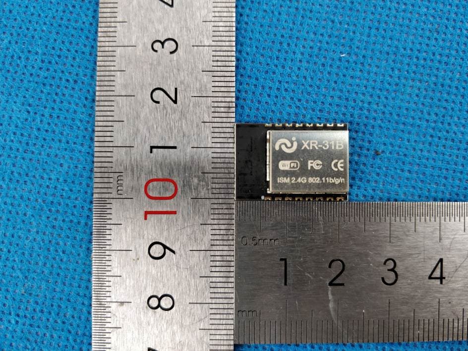
Click to zoom
Application Details
- Equipment Class
- DTS - Digital Transmission System
- Date of Grant
- Jun 01, 2020
- Application Purpose
- Original Equipment
- Date of Application
- May 31, 2020
- Equipment Note
- 2.4G WIFI module
- Frequency Range
- 2412.00000000 - 2462.00000000
- Country
- China
Documents & Files
Document Text
Text extracted from the exhibit documents filed with the FCC. Open a document above to read the original.
Users Manual
XR-31B WIFI module Copyright © 2019 ShenzhenJiXinInteligence Co., Ltd All Rights Reserved XR-31B User manual Version V1 Copyright ©2019 XR-31B WIFI module Copyright © 2019 ShenzhenJiXinInteligence Co., Ltd All Rights Reserved Page 1 of 14 This device is intended only for OEM integrators under the following conditions: 1)The antenna must be installed such that 20 cm is maintained between the antenna and users, and 2)This device and its antenna(s) must not be co‐located with any other transmitters except in accordance with FCC multi‐transmitter product procedures. Referring to the multi‐transmitter policy, multiple‐transmitter(s) and module(s) can be operated simultaneously without C2P. 3)For all products market in US, OEM has to limit the operation channels in CH1 to CH11 for 2.4G band by supplied firmware programming tool. OEM shall not supply any tool or info to the end‐user regarding to Regulatory Domain change. USERS MANUAL OF THE END PRODUCT: In the users manual of the end product, the end user has to be informed to keep at least 20cm separation with the antenna while this end product is installed and operated. The end user has to be informed that the FCC radio-frequency exposure guidelines for an uncontrolled environment can be satisfied. The end user has to also be informed that any changes or modifications not expressly approved by the manufacturer could void the user's authority to operate this equipment . If the size of the end product is smaller than 8x10cm, then additional FCC part 15.19 statement is required to be available in the users manual: This device complies with Part 15 of FCC rules. Operation is subject to the following two co nditions: (1) this device may not cause harmful interference and (2) this device must accept any interference received, including interference that may cause undesired operation. LABEL OF THE END PRODUCT: The final end product must be labeled in a visible area with the following " Contains FCC ID: 2AVTT-XR31B ". If the size of the end product is larger than 8x10cm, then the following FCC part 15.19 statement has to also be available on the label: This device complies with Part 15 of FCC rules. Operation is subject to the following two conditions: (1) this device may not cause harmful interference and (2) this device must accept any interference received, including interference that may cause undesired operation. Labels: Host Device must contain the following label on the outside of the unit: Contains FCC ID:2AVTT-XR31B Installation Guidance The final host / module combination may also need to be evaluated against the FCC Part 15B criteria for unintentional radiators in order to be properly authorized for operation as a Part 15 digital device. The user’s manual or instruction manual for an intentional or unintentional radiator shall caution the user that changes or modifications not expressly approved by the party responsible for compliance could void the user's authority to operate the equipment. In cases where the manual is provided only in a form other than paper, such as on a computer disk or over the Internet, the information required by this section may be included in the manual in that alternative form, provided the user can reasonably be expected to have the capability to access information in that form. To ensure compliance with all non-transmitter functions the host manufacturer is responsible for ensuring compliance with the module(s) installed and fully operational. For example, if a host was previously authorized as an unintentional radiator under the Declaration of Conformity procedure without a transmitter certified module and a module is added, the host manufacturer is responsible for ensuring that the after the module is installed and operational the host continues to be compliant with the Part 15B unintentional radiator requirements. The FCC rule/s for this module are CFR 47 Part 15 Subpart C. Additional testing and certification may be necessary when multiple modules are used. XR-31B WIFI module Copyright © 2019 Shenzhen JiXinInteligence Co., Ltd All Rights Reserved Page 2 of 14 1. Product Overview XR-31B WiFi module was developed for a wide range of IoT applications, Its core processor XR808 integrated the ARM Cortex-M4F 32-bit microcontroller in a smaller package, supporting the master clock frequency up to 160MHz; Integrated high-performance WLAN system with Wi-Fi MAC/BB/RF/PA/LNA units; Integrated advanced power management units for ultra-low power consumption with multiple sleep modes and fast wake-up mechanisms; Integrated hardware encryption engine to supports AES/DES/3DES/SHA-1/ MD5/ CRC/ SHA256/TRNG; Integrated large memory and rich peripherals. XR-31B WiFi module supports standard IEEE802.11 b/g/n protocol, supports RTOS, with a complete TCP/IP protocol stack, Users can use the module to add networking capabilities to existing devices, or can use it as a master design wireless network product, XR808 can be started directly from external flash memory, the on-chip high-speed buffer memory helps improve system performance and reduce RAM requirements. XR-31B WIFI module Copyright © 2019 Shenzhen JiXinInteligence Co., Ltd All Rights Reserved Page 3 of 14 1.1 Appearance Dimensions XR-31B WIFI module Copyright © 2019 Shenzhen JiXinInteligence Co., Ltd All Rights Reserved Page 4 of 14 1.2 Features ◼ EEE 802.11b/g/n, 1x1 SISO 2.4GHz ◼ Built-in ARM Cortex-M4F 32bit MCU with main frequency from 32KHz to 160MHz, support RTOS ◼ Built-in 256KB SRAM and 160KB ROM ◼ Support external Flash and eXecute In Place(XIP) ◼ 8 shared universal DMA channels ◼ Built-in 6 ways 12bit SAR type A/D converter ◼ Built-in Wi-Fi MAC/ BB/RF/PA/LNA ◼ Support WEP, WPA/WPA2, WPS2.0 ◼ Support UART/GPIO/ADC/PWM/I2C/SPI interface ◼ Use SMD-16 assemble model ◼ Support multiple sleep modes and current as low as 4uA in deep sleep mode ◼ Support AES/DES/3DES/SHA/MD5/CRC encryption engine ◼ Support STA/AP/STA+AP operation modes ◼ Support Smart Config/AirKiss (WeC…
Text truncated - open the document above for the full version.
Cover Letter(s)
C5266091_X8_Ed.1 1/1 Letter of Authorization Shenzhen Jixin intelligence Co., Ltd Company: Shenzhen Jixin intelligence Co., Ltd Address: A505 Room, Business Building, Suojia Science Park, Xixiang, Baoan District, Shenzhen, China Product Name: 2.4G WIFI module Model Number: XR-31B FCC Identifier: 2AVTT-XR31B We authorize LGAI Technological Center S.A., Ronda de la Font del Carme, s/n, 08193 Bellaterra, Spain, to act on our behalf on all matters concerning the above named equipment. Any individual within LGAI Technological Center S.A. is authorized to act on our behalf and take action on the application. We declare that authorize LGAI Technological Center S.A., Ronda de la Font del Carme, s/n, 08193 Bellaterra, Spain, is allowed to forward all information related to the approval project to the Federal Communication Commission and to discuss any issues concerning the approval application. Any and all acts carried out by LGAI Technological Center S.A. on our behalf shall have the same effect as acts of our own. Name: Huabin Fu Date: 5/28/2020 Title: CEO Signature of applicant:
Cover Letter(s)
C5266091_X10_Ed.1 1/1 Shenzhen Jixin intelligence Co., Ltd Office of Engineering Technology Federal Communications Commission 7435 Oakland Mills Road Columbia, MD 21046 Date: 5/28/2020 Subject: Request for Confidentiality FCC ID: 2AVTT-XR31B To Wh om It May Concern, Pursuant to the provisions of Sections 0.457 and 0.459 of Commission's rules (47CFR0.457, 0.459), we are requesting the Commission to withhold the following attachment(s) as confidential document from public disclosure. ExhibitsLong-Term Confidentiality Short-Term Confidentiality ID Label/Location No No Attestation Statement No No External Photos No Block Diagram Schematics Test Report No No Test Setup Photos No User’s Manual Internal Photos Parts List / Tune Up RF Exposure Info Operational Description Cover Letter(s) No No SDR Software / Security Info No Above m entioned document contains detailed system and equipment description are considered as proprietary information in operation of the equipment. The public disclosure of above documents might be harmful to our company and would give competitor an unfair advantage in the market. It is our understanding that all measurement test reports, FCC ID label format and correspondent during certification review process cannot be granted as confidential documents and those information will be available for public review once the grant of equipment authorization is issued. Sincerely, Signature: Name: Huabin Fu 5/28/2020 Title: CEO
Cover Letter(s)
C5266091_X9_Ed.1 1/1 Shenzhen Jixin intelligence Co., Ltd Modular Transmitter Approval Request Federal Communications Commission Equipment Authorizatio n Branch 7435 Oakland Mills Road Columbia, MD 21046 Company name: Shenzhen Jixin intelligence Co., Ltd FCC ID: 2AVTT-XR31B Gentlemen, In accordance with 47CFR 15.212 Modular Transmitters and KDB 996369 D01 ‘Module Certification Guide v01r04’. FCC ID 2AVTT-XR31B has been examined against the following requirements. Requirement per 15.212 and KDB 996369 D01 ‘Modular Certification Guide v01r04 Explanation from Grantee (do not write yes/no, but explain why product complies/how it is achieved) The radio elements must have the radio frequency circuitry shielded. Physical components and tuning capacitor(s) may be located external to the shield, but must be on the module assembly Yes, The module has its own RF shield The module must have buffered modulation/data inputs to ensure that the device will comply with Part 15 requirements with any type of input signal Yes, All inputs to the modules are buffered through logic or microprocessor inputs. The module must contain power supply regulation on the module Module with power regulation and support for DC 3.3V input The module must contain a permanently attached antenna, or contain a unique antenna connector, and be marketed and operated only with specific antenna(s), per Sections 15.203, 15.204(b), 15.204(c), 15.212(a), 2.929(b) Device is equipped with Integral antenna. The module must demonstrate compliance in a stand- alone configuration The module has been tested in a standalone configuration, see report for details The module must be labelled with its permanently affixed FCC ID label, or use an electronic display (See KDB Publication 784748 about labelling requirements) The module has its own FCC ID number. See the label for details. The module must comply with all specific rules applicable to the transmitter including all the conditions provided in the integration instructions by the grantee The module meets any specific rules or operational requirements applicable to the transmitter The module must comply with RF exposure requirements The module complies with any applicable RF exposure requirements, as detailed in the instructions. Name: Huabin Fu Date: 2020-05-28 Title: CEO Signature of applicant
External Photos
1 - Page 1 of 2 - Report No.: MTi20022811-7E1-1 Tel:(86-755)88850135 Fax: (86-755) 88850136 Web: http://www.mtitest.com E-mail: [email protected] Address: No.102A & 302A, East Block, Hengfang Industrial Park, Xingye Road, Xixiang, Bao'an District, Shenzhen, Guangdong, China APPENDIX 1: EUT PHOTO Photo 1 (For model XR-31B) Photo 2
ID Label/Location Info
SIZE:10mm*3mm FCC ID :2AVTT-XR31B
Internal Photos
1 - Page 2 of 2 - Report No.: MTi20022811-7E1-1 Tel:(86-755)88850135 Fax: (86-755) 88850136 Web: http://www.mtitest.com E-mail: [email protected] Address: No.102A & 302A, East Block, Hengfang Industrial Park, Xingye Road, Xixiang, Bao'an District, Shenzhen, Guangdong, China Photo 3 ----END OF REPORT---- 2.4GWiFi antenna
RF Exposure Info
This test report is valid for the tested samples only. It cannot be reproduced except in full without prior written consent of Shenzhen Microtest Co., Ltd. Tel:(86-755)88850135 Fax: (86-755) 88850136 Web: http://www.mtitest.com E-mail: [email protected] Address: No.102A & 302A, East Block, Hengfang Industrial Park, Xingye Road, Xixiang, Bao'an District, Shenzhen, Guangdong, China MPE REPORT FCC ID:2AVTT-XR31B Date of issue: Apr. 02, 2020 Report number: MTi20022811-7E2 Sample description: 2.4G WIFI module Model(s): XR-31B Applicant: Shenzhen Jixin intelligence Co., Ltd Address: A505 Room, Business Building, Suojia Science Park, Xixiang, Baoan District, Shenzhen Date of test: May 05, 2019 to Apr. 02, 2020 Shenzhen Microtest Co., Ltd. http://www.mtitest.com - Page 2 of 4 - Report No.: MTi20022811-7E2 Tel:(86-755)88850135 Fax: (86-755) 88850136 Web: http://www.mtitest.com E-mail: [email protected] Address: No.102A & 302A, East Block, Hengfang Industrial Park, Xingye Road, Xixiang, Bao'an District, Shenzhen, Guangdong, China TEST RESULT CERTIFICATION Applicant’s name: Shenzhen Jixin intelligence Co., Ltd Address: A505 Room, Business Building, Suojia Science Park, Xixiang, Baoan District, Shenzhen Manufacture's name: Shenzhen Jixin intelligence Co., Ltd Address: A505 Room, Business Building, Suojia Science Park, Xixiang, Baoan District, Shenzhen Product name: 2.4G WIFI module Trademark: N/A Model and/or type reference . : XR-31B Serial model ........................... : N/A RF exposure procedures ....... : KDB 447498 D01 v06 This device described above has been tested by Shenzhen Microtest Co., Ltd and the test results show that the equipment under test (EUT) is in compliance with the FCC requirements. And it is applicable only to the tested sample identified in the report. Tested by: Danny Xu Apr. 02, 2020 Reviewed by: Leo Su Apr. 02, 2020 Approved by: Tom Xue Apr. 02, 2020 - Page 3 of 4 - Report No.: MTi20022811-7E2 Tel:(86-755)88850135 Fax: (86-755) 88850136 Web: http://www.mtitest.com E-mail: [email protected] Address: No.102A & 302A, East Block, Hengfang Industrial Park, Xingye Road, Xixiang, Bao'an District, Shenzhen, Guangdong, China RF EXPOSURE EVALUATION According to FCC 1.1310: The criteria listed in the following table shall be used to evaluate the environment impact of human exposure to radio frequency (RF) Radiation as specified in §1.1307(b) Limits for Maximum Permissible Exposure (MPE) MPE Calculation Method Friis transmission formula: Pd= (Pout*G)\ (4*pi*R 2 ) Where Pd= Power density in mW/cm2 Pout=output power to antenna in mW G= Numeric gain of the antenna relative to isotropic antenna Pi=3.1415926 R= distance between observation point and center of the radiator in cm(20cm) Pd the limit of MPE, 1mW/cm2. If we know the maximum gain of the antenna and total power input to the antenna, through the calculation, we will know the distance where the MPE limit is reached. - Page 4 of 4 - Report No.: MTi20022811-7E2 Tel:(86-755)88850135 Fax: (86-755) 88850136 Web: http://www.mtitest.com E-mail: [email protected] Address: No.102A & 302A, East Block, Hengfang Industrial Park, Xingye Road, Xixiang, Bao'an District, Shenzhen, Guangdong, China Measurement Result WIFI: Operation Frequency: WIFI 802.11b/g/n HT20: 2412-2462MHz, Power density limited: 1mW/ cm 2 Antenna Type: Wifi Antenna: PCB Antenna; Antenna gain: 2dBi R=20cm mW=10^(dBm/10) antenna gain Numeric=10^(dBi/10)= 10^(2/10)=1.58 Channel Freq. (MHz) modulation conducted power Tune- up power Max Antenna Evaluation result at 20cm Power density Limits (dBm) (dBm) tune-up power Gain Power density(mW/cm2 ) (mW/cm2) (dBm) (mW) Numeric Ant A Ant A Ant A Ant A Ant A Ant A 2412 802.11b 16.25 17±1 18 63.095734 1.58 0.01983 1 2437 17.78 17±1 18 63.095734 1.58 0.01983 1 2462 16.91 17±1 18 63.095734 1.58 0.01983 1 2412 802.11g 14.81 14±1 15 31.622777 1.58 0.00994 1 2437 14.56 14±1 15 31.622777 1.58 0.00994 1 2462 14.01 14±1 15 31.622777 1.58 0.00994 1 2412 802.11n H20 14.41 14±1 15 31.622777 1.58 0.00994 1 2437 14.38 14±1 15 31.622777 1.58 0.00994 1 2462 13.97 14±1 15 31.622777 1.58 0.00994 1 Conclusion: For the max result: 0.01983≤ 1.0 for 1g SAR, No SAR is required. ----END OF REPORT----
Test Report
This test report is valid for the tested samples only. It cannot be reproduced except in full without prior written consent of Shenzhen Microtest Co., Ltd. Tel:(86-755)88850135 Fax: (86-755) 88850136 Web: http://www.mtitest.com E-mail: [email protected] Address: No.102A & 302A, East Block, Hengfang Industrial Park, Xingye Road, Xixiang, Bao'an District, Shenzhen, Guangdong, China Test Report FCCID:2AVTT-XR31B Date of issue: Apr. 02, 2020 Report number: MTi20022811-7E1 Sample description: 2.4G WIFI module Model(s): XR-31B Applicant: Shenzhen Jixin intelligence Co., Ltd Address: A505 Room, Business Building, Suojia Science Park, Xixiang, Baoan District, Shenzhen Date of test: Mar. 17, 2020 to Apr. 02, 2020 Shenzhen Microtest Co., Ltd. http://www.mtitest.com - Page 2 of 48 - Report No.: MTi20022811-7E1 Tel:(86-755)88850135 Fax: (86-755) 88850136 Web: http://www.mtitest.com E-mail: [email protected] Address: No.102A & 302A, East Block, Hengfang Industrial Park, Xingye Road, Xixiang, Bao'an District, Shenzhen, Guangdong, China Table of Contents 1 GENERAL INFORMATION ...................................................................................................................................... 5 1.1 DESCRIPTION OF EUT ................................................................................................................................................... 5 1.2 OPERATION CHANNEL LIST .............................................................................................................................................. 6 1.3 TEST CHANNEL LIST ....................................................................................................................................................... 6 1.4 ANCILLARY EQUIPMENT LIST ........................................................................................................................................... 6 1.5 DESCRIPTION OF SUPPORT UNITS .................................................................................................................................... 6 2 SUMMARY OF TEST RESULTS ................................................................................................................................. 7 3 TEST FACILITIES AND ACCREDITATIONS .................................................................................................................. 8 3.1 TEST LABORATORY ........................................................................................................................................................ 8 3.2 ENVIRONMENTAL CONDITIONS ........................................................................................................................................ 8 3.3 MEASUREMENT UNCERTAINTY ........................................................................................................................................ 8 3.4 TEST SOFTWARE ........................................................................................................................................................... 8 4 EQUIPMENT LIST .................................................................................................................................................. 9 5 TEST RESULT ....................................................................................................................................................... 10 5.1 ANTENNA REQUIREMENT ............................................................................................................................................. 10 5.1.1 Standard requirement ....................................................................................................................................... 10 5.1.2 EUT antenna ..................................................................................................................................................... 10 5.2 PEAK OUTPUT POWER ................................................................................................................................................. 11 5.2.1 Limit .................................................................................................................................................................. 11 5.2.2 Test setup .......................................................................................................................................................... 11 5.2.3 Test procedure ................................................................................................................................................... 11 5.2.4 Test results ........................................................................................................................................................ 12 5.3 POWER SPECTRAL DENSITY ........................................................................................................................................... 13 5.3.1 Limit .................................................................................................................................................................. 13 5.3.2 Test setup .......................................................................................................................................................... 13 5.3.3 Test procedure ................................................................................................................................................... 13 5.3.4 Test results ........................................................................................................................................................ 14 5.4 CONDUCTED EMISSION ................................................................................................................................................ 17 5.4.1 Limits ................................................................................................................................................................. 17 5.4.…
Text truncated - open the document above for the full version.
Contact Information
Applicant
Huabin Fu(CEO)
Technical Contact
Test Firm
Shenzhen Microtest Co., Ltd.Selby Liao
[email protected]0755-88850135-1193
Technical Specifications
| # | Rule Parts | Frequency Range | Power Output |
|---|---|---|---|
| 1 | 15C | 2.41 GHz - 2.46 GHz | 60.00 mW |
Other Applications from Shenzhen Jixin intelligence Co., Ltd
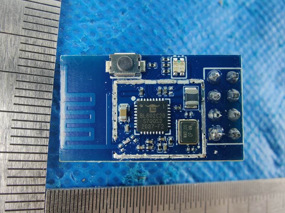
2AVTT-BL01S
Mar 02, 20212.4G WIFI/BT module
Equipment Class
DTS - Digital Transmission System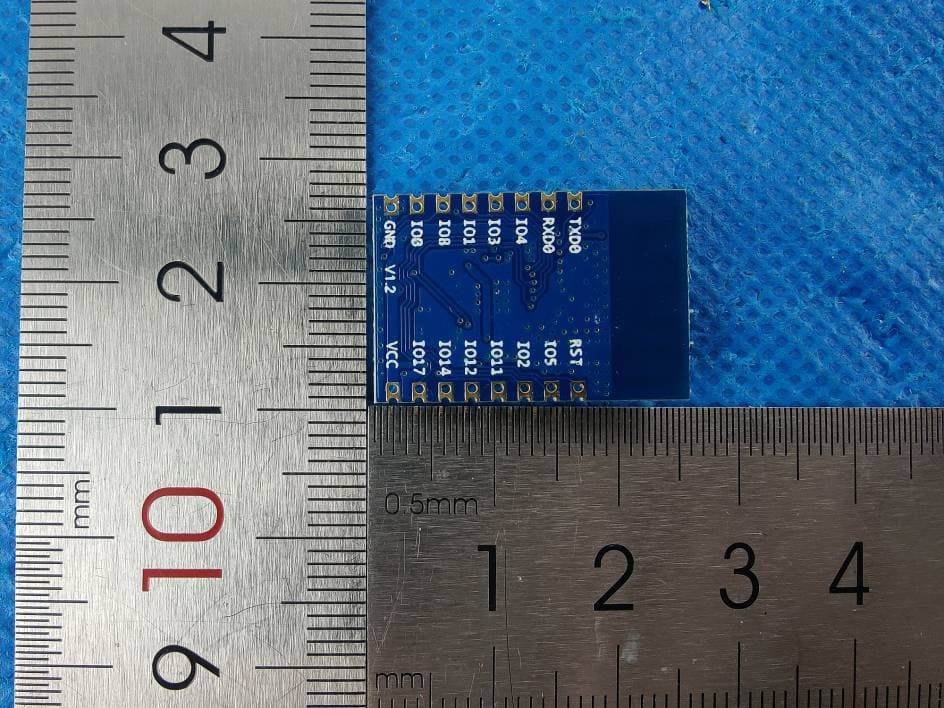
2AVTT-BL62B
Mar 02, 20212.4G WIFI/BT module
Equipment Class
DTS - Digital Transmission System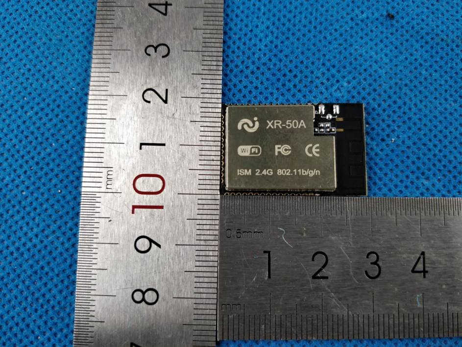
2AVTT-XR50A
Jun 29, 20202.4G WIFI module
Equipment Class
DTS - Digital Transmission System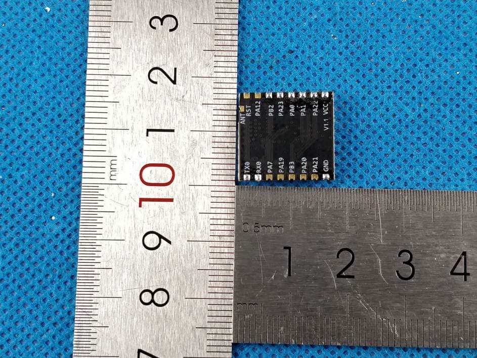
2AVTT-XR22A
Jun 29, 20202.4G WIFI module
Equipment Class
DTS - Digital Transmission System
2AVTT-XR21A
Jun 21, 20202.4G WIFI module
Equipment Class
DTS - Digital Transmission System