2AVUKRTCGE01Ceiling Mounted Detection Sensor
Zhanzuo (Beijing) Technology, Ltd.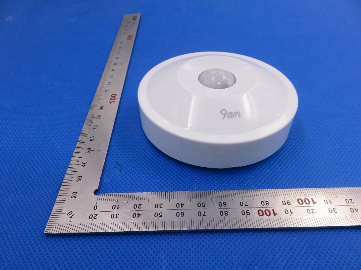
Click to zoom
Application Details
- Equipment Class
- DTS - Digital Transmission System
- Date of Grant
- May 20, 2020
- Application Purpose
- Original Equipment
- Date of Application
- May 20, 2020
- Equipment Note
- Ceiling Mounted Detection Sensor
- Frequency Range
- 2402.00000000 - 2480.00000000
- Country
- China
Documents & Files
Document Text
Text extracted from the exhibit documents filed with the FCC. Open a document above to read the original.
Users Manual
Ceiling Mounted Detection Sensor RTCGE01 Datasheet General Specifications Features Dimensions Weight (with battery) Casing 94mm in diameter, 38mm in thickness 83.5g ABS plastic Environment Requirements Operating temperature Operating humidity Mounting location Mounting Detection angle Detection distance -1045 095%RH, no condensation 3m away from the floor Srews / Adhesives 360° ≤7m Power Battery Battery life AAA battery x 2 5 years Others IP rating Standards IP52 EN 60669-1 EN 60669-2-1 Dynamic Human Body Detection * RTCGE01 Ceiling Mounted Detection Sensor adopts the third generation of passive infrared sensors (PIR) detec- tion technology. With built-in high-precision algorithm unit, RTCGE01 can automatically adapt to specific room environments and filter out interference caused by temperature and humidity changes. The sensor can effectively identif y people up to a range of 7 meters. Powered by two easily replaceable AAA batteries, giving the sensor a life span of over 5 years. RTCGE01 is fixed in a central location of a room using an adhesive, with an installation time of <1 minute. When a person moves within the detection range of the RTCGE01, the sensor can respond almost instantaneously and report the status change. Bluetooth Mesh Technology Bluetooth Mesh technology used in RTCGE01 is a global wireless standard for communication between smart devices in industrial automation environments. Bluetooth Mesh technology uses a reliable mesh network to keep devices connecte d and working together while providing excellent battery life. Dynamic Temperature Compensation Dynamic temperature compensation enables RTCGE01 to automatically monitor the ambient temperature and adjust the signal processing algorithms to maintain normal sensing perfor- mance in varying temperatures. Real-time Data Reporting and Offline Caching RTCGE01 reports measurement data through the gateway with a delay of less than 100 ms. If the sensor is offline, the data will be cached locally and transmitted after the network connection is restored. The above data is measured by 9am laboratory, and may be affected by environmental factors. • www.9amtech.com • contact @9amtech.com • 400-037-8109 Installation Guide * The recommended installation height is between 2m and 3m. Installed below 2m or above 3m, blind spots will appear and some area cannot be detected. 2-3m 0m2m2m4.5m4.5m7m7m NOTE: This equipment has been tested and found to comply with the limits for a Class B digital device, pursuant to part 15 of the FCC Rules. These limits are designed to provide reasonable protection against harmful interference in a residential installation. This equipment generates uses and can radiate radio frequency energy and, if not installed and used in accordance with the instructions, may cause harmful interference to radio communica- tions. However, there is no guarantee that interference will not occur in a particular installation. If this equipment does cause harmful interference to radio or television reception, which can be determined by turning the equipment off and on, the user is encouraged to try to correct the interference by one or more of the following measures: - Reorient or relocate the receiving antenna. - Increase the separation between the equipment and receiver. -Connect the equipment into an outlet on a circuit different from that to which the receiver is connected. -Consult the dealer or an experienced radio/TV technician for help Changes or modifications not expressly approved by the party responsible for compliance could void the user's authority to operate the equipment. This device complies with Part 15 of the FCC Rules. Operation is subject to the following two conditions: (1) this device may not cause harmful interference, and (2) this device must accept any interference received, including interference that may cause undesired operation. RF Exposure Warning Statements: This equipment complies with FCC radiation exposure limits set forth for an uncontrolled environment. This equipment shall be installed and operated with minimum distance 20cm between the radiator & body.
Cover Letter(s)
Zhanzuo (Beijing) Technology, Ltd. [2020-05-18] Federal Communications Commission 445 12 th Street SW Washington, DC 20554 Subject: Limited Agency Agreement Zhanzuo (Beijing) Technology, Ltd. FCC ID: 2AVUKRTCGE01 To Whom It May Concern: We, Zhanzuo (Beijing) Technology, Ltd. hereby authorized Intertek Testing Services to act as our Agent for the purpose of preparing application for FCC ID number (2AVUKRTCGE01) under all applicable parts of the FCC rules and regulations. The effective date of this limited agency agreement is (2020-05-18). The Limited Agency Agreement expires until further notice, unless sooner terminated or extended by written notice to Intertek Testing Services and the Federal Communications Commission. This is to advise that we are in full compliance with the Anti-Drug Abuse Act. The applicant is not subject to a denial of federal benefits pursuant to Section 5301 of the Anti-Drug Act of 1988, 21 U.S.C. 862, and no party to the application is subject to a denial of federal benefits pursuant to that section. If you have any questions or comments, please do not hesitate to contact me. Sincerely, [Signature] Zhanzuo (Beijing) Technology, Ltd. Contact person: Hao Wu
Cover Letter(s)
Zhanzuo (Beijing) Technology, Ltd. 2020-05-15 Federal Communication Commission Authorization and Evaluation Division FCC ID: 2AVUKRTCGE01 Re: Confidentiality Request Pursuant to Sections 0.457 and 0.459 of the Commission’s Rules, the applicant hereby requests confidential treatment of information applied this application as outlined below: 1: Block Diagram 2: Schematics 3: Operational Description 4: Parts List The above materials contain trade secrets and proprietary information not customarily released to the public. The public disclosure of these matters might be harmful to the applicant and provide unjustified benefits to its competitors. The Applicant understands that pursuant to Rules 0.457, disclosure of this Application and all accompanying documentation will not be made before the date of the Grant for this application. Sincerely, Zhanzuo (Beijing) Technology, Ltd. Contact person: Hao Wu
External Photos
External Photos TOP VIEW OF EUT BOTTOM VIEW OF EUT FRONT VIEW OF EUT BACK VIEW OF EUT LEFT VIEW OF EUT RIGHT VIEW OF EUT VIEW OF EUT(PORT)
ID Label/Location Info
FCC ID Label Location Size: 30mm*30mm FCC ID: 2AVUKRTCGE01
Internal Photos
Internal Photos OPEN VIEW OF EUT VIEW OF BATTERY INTERNAL VIEW OF EUT-1 INTERNAL VIEW OF EUT-2 INTERNAL VIEW OF EUT-3 BT Antenna
RF Exposure Info
RF EXPOSURE EVALUATION 1. PRODUCT INFORMATION Product Description Ceiling Mounted Detection Sensor Model Name RTCGE01, RTCG FCC ID 2AVUKRTCGE01 2. EVALUATION METHOD According to 447498 D01 General RF Exposure Guidance v05 The 1-g and 10-g SAR test exclusion thresholds for 100 MHz to 6 GHz at test separation distances ≤ 50 mm are determined by: [(max. power of channel, including tune-up tolerance, mW)/(min. test separation distance, mm)] ·[√f(GHz)] ≤ 3.0 for 1-g SAR and ≤ 7.5 for 10-g extremity SAR. Where f(GHz) is the RF channel transmit frequency in GHz Power and distance are rounded to the nearest mW and mm before calculation 3. CALCULATION P t = -0.986dBm=0.80mW The value of the Maximum output power P t is referred to the test report of the CFR47 §15.247. The result for RF exposure evaluation SAR=(0.80mW/5mm) .[√2.402GHz)]= 0.09<3.0 for 1-g SAR and ≤ 7.5 for 10-g extremity SAR. 4. CONCLUSION The SAR evaluation is not required.
Test Report
Page 1 of 45 FCC Test Report Report No.: AGC09880200403FE02 FCC ID : 2AVUKRTCGE01 APPLICATION PURPOSE : Original Equipment PRODUCT DESIGNATION : Ceiling Mounted Detection Sensor BRAND NAME : 9am MODEL NAME : RTCGE01, RTCG APPLICANT : Zhanzuo (Beijing) Technology, Ltd. DATE OF ISSUE : May 15, 2020 STANDARD(S) : FCC Part 15.247 REPORT VERSION : V1.0 Attestation of Global Compliance (Shenzhen) Co., Ltd CAUTION: This report shall not be reproduced except in full without the written permission of the test laboratory and shall not be quoted out of context. Report No.: AGC09880200403FE02 Page 2 of 45 REPORT REVISE RECORD Report Version Revise Time Issued Date Valid Version Notes V1.0 / May 15, 2020 Valid Initial Release Report No.: AGC09880200403FE02 Page 3 of 45 TABLE OF CONTENTS 1. VERIFICATION OF COMPLIANCE ............................................................................................................... 5 2. GENERAL INFORMATION ............................................................................................................................ 6 2.1. PRODUCT DESCRIPTION .................................................................................................................... 6 2.2.TABLE OF CARRIER FREQUENCYS .................................................................................................... 6 2.3. RELATED SUBMITTAL(S)/GRANT(S) ................................................................................................... 7 2.4.TEST METHODOLOGY .......................................................................................................................... 7 2.5. SPECIAL ACCESSORIES ..................................................................................................................... 7 2.6. EQUIPMENT MODIFICATIONS ............................................................................................................. 7 3. MEASUREMENT UNCERTAINTY ................................................................................................................. 8 4. DESCRIPTION OF TEST MODES ................................................................................................................. 9 5. SYSTEM TEST CONFIGURATION ............................................................................................................. 10 5.1 CONFIGURATION OF TESTED SYSTEM ............................................................................................ 10 5.2. EQUIPMENT USED IN TESTED SYSTEM .......................................................................................... 10 5.3. SUMMARY OF TEST RESULTS .......................................................................................................... 10 6. TEST FACILITY ............................................................................................................................................ 11 7. PEAK OUTPUT POWER ............................................................................................................................. 12 7.1. MEASUREMENT PROCEDURE .......................................................................................................... 12 7.2. TEST SET-UP (BLOCK DIAGRAM OF CONFIGURATION) ................................................................. 12 7.3. LIMITS AND MEASUREMENT RESULT .............................................................................................. 13 8. 6 DB BANDWIDTH ...................................................................................................................................... 15 8.1. MEASUREMENT PROCEDURE .......................................................................................................... 15 8.2. TEST SET-UP (BLOCK DIAGRAM OF CONFIGURATION) ................................................................. 15 8.3. LIMITS AND MEASUREMENT RESULTS ........................................................................................... 15 9. CONDUCTED SPURIOUS EMISSION ........................................................................................................ 17 9.1. MEASUREMENT PROCEDURE .......................................................................................................... 17 9.2. TEST SET-UP (BLOCK DIAGRAM OF CONFIGURATION) ................................................................. 17 9.3. MEASUREMENT EQUIPMENT USED ................................................................................................ 17 9.4. LIMITS AND MEASUREMENT RESULT .............................................................................................. 17 10. MAXIMUM CONDUCTED OUTPUT POWER SPECTRAL DENSITY ....................................................... 22 10.1. MEASUREMENT PROCEDURE ........................................................................................................ 22 10.2. TEST SET-UP (BLOCK DIAGRAM OF CONFIGURATION) ............................................................... 22 10.3. MEASUREMENT EQUIPMENT USED .............................................................................................. 22 10.4. LIMITS AND MEASUREMENT RESULT ............................................................................................ 22 11. RADIATED EMISSION ............................................................................................................................... 24 Report No.: AGC09880200403FE02 Page 4 of 45 11.1. MEASUREMENT PROCEDURE ........................................................................................................ 24 11.2. TEST SETUP ..................................................................................................................................... 25 11.3. LIMITS AND MEASUREMENT RESULT ............................................................................................ 26 11.4. TEST RESULT ..........................................................................…
Text truncated - open the document above for the full version.
Test Setup Photos
Test Setup Photos RADIATED EMISSION TEST SETUP BELOW 1GHZ RADIATED EMISSION TEST SETUP ABOVE 1GHZ CONDUCTED TEST SETUP
Contact Information
Applicant
Hao Wu
Technical Contact
Attestation of Global Compliance (Shenzhen) Co., LYimi Zhao
[email protected]86-755-29081977
2F.,No.2 Building, Huafeng No.1 Technical Industri · Shenzhen · China
Test Firm
Attestation of Global Compliance (Shenzhen) Co., LDoris Li
[email protected]+86-755-25234088
Technical Specifications
| # | Rule Parts | Frequency Range | Power Output |
|---|---|---|---|
| 1 | 15C | 2.40 GHz - 2.48 GHz | 800.00 µW |
Other Applications from Zhanzuo (Beijing) Technology, Ltd.
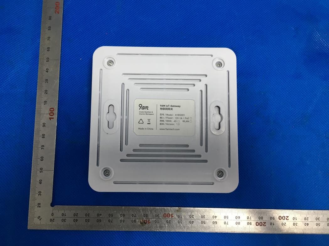
2AVUKA181G001
Aug 12, 2020Bluetooth Mesh Gateway
Equipment Class
DTS - Digital Transmission System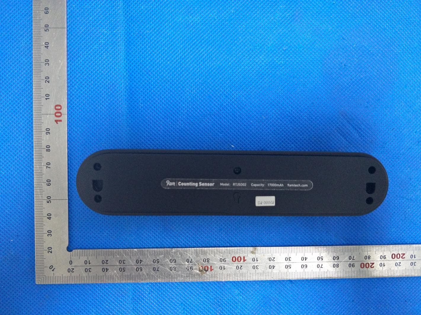
2AVUKRTJSD02
Jun 15, 2020Counting Sensor
Equipment Class
DTS - Digital Transmission System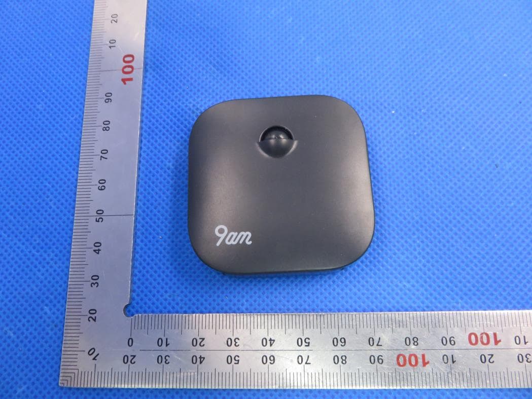
2AVUKRTCZA04
Mar 24, 2020Occupy Sensor
Equipment Class
DTS - Digital Transmission System