2AW5N-P6P6 bluetooth speaker
Shenzhen Guye Technology Co., Ltd.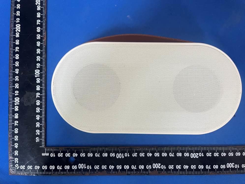
Click to zoom
Application Details
- Equipment Class
- DSS - Part 15 Spread Spectrum Transmitter
- Date of Grant
- Jul 27, 2023
- Application Purpose
- Original Equipment
- Date of Application
- Jul 27, 2023
- Equipment Note
- P6 bluetooth speaker
- Frequency Range
- 2402.00000000 - 2480.00000000
- Country
- China
Documents & Files
Document Text
Text extracted from the exhibit documents filed with the FCC. Open a document above to read the original.
Users Manual
In order to better use the product performance, please read the use manual carefully and charge the speaker kits fully before the first use. Long Press: Next Song Short Press: Vol+ DC 5V Charging Port AUX TF Card Slot Long Press: Power on/off Short Press: Light Switch Short Press: Play/Pause Long Press: Remove Original Voice Short Press: TF card /Bluetooth/AUX Mode Switch Long Press: Prev Song Short Press: Vol- Speaker Diagram Speaker Operating Instruction Mobile Phone Conntecting via Bluetooth 1.Long press the power button for 3 seconds to turn on the speaker, and Bluetooth indicator will keep flashing. 2. Turn on the Bluetooth setting on the phone, choose the Bluetooth named "VS-6633" for paring , You will hear a quick sound after connecting successfully 3. Now, you can play the music from the music player or Karaoke APPs on your phone. Note: The mic can't work with 2 bluetooth devices at the time. If you would like to connect a second device via bluetooth, please delete the first one from your mobile phone. 1.When the battery is out of power, the machine will be off automatically. 2.Please use the original charging cable. When charging, the indicator turns red. 3.The charging time is about 4-5 hours. After fully charged, the indicator will be off automatically. 4.The working time is about 4-5 hours under normal operation. Model No: P 6 Mic Connection: Wireless connection Mic: HiFi Pickup Speaker: 5W*2 Frequency Response Range: 50Hz- 20KHz Distortion: <=3% Maximum Sound Pressure Level: >= 90dB Bluetooth Transmission Distance: 10M Mic Connection Distance: 10M Input Charging Voltage: 5V Battery Specification :3.7V 3000mAh battery Working Time: 4-5H Charging Time: 4-5H Working Temperature: -10°C~45°C Troubleshooting Made in China 1. If your machine is emitting smoke or experiencing any other abnormal behavior, please contact our customer service for assistance. 2. If the machine has been rained on or exposed to moisture, please place it in a well-ventilated area to dry. 3. Please do not use high temperatures to bake the machine, as this can cause damage or lead to the malfunction of internal components. 4. This product should not be exposed to conditions of excessive heat, such as direct sunlight or fire. 5. Please do not throw away the machine to prevent it from dropping and getting damaged. 6. When using a power adapter for power, the power adapter should meets CCC certification and standard requirements. Cause No sound from the speaker The volume is too low Turn up the volume of both the device and the speaker Speaker doesn't turn on Lower power Charge the speaker Fail to connect Bluetooth Has connected other device Delete it from Bluetooth Sound distortion Volume is too high or the power is too low Turn down the volume of your device or charge the speaker Not playing music when plugged into a TF card The format is wrong or loose contact Change the music format, or unplug and plug into the TF card again Speaker not charging Something wrong with the charging cable or loose contact Unplug the charging cable and plug it into again. Or try a different charging cable FCC Statement This equipment has been tested and found to comply with the limits for a Class B digital device, pursuant to part 15 of the FCC Rules. These limits are designed to provide reasonable protection against harmful interference in a residential installation. This equipment generates, uses and can radiate radio frequency energy and, if not installed and used in accordance with the instructions, may cause harmful interference to radio communications. However, there is no guarantee that interference will not occur in a particular installation. If this equipment does cause harmful interference to radio or television reception, which can be determined by turning the equipment off and on, the user is encouraged to try to correct the interference by one or more of the following measures: —Reorient or relocate the receiving antenna. —Increase the separation between the equipment and receiver. —Connect the equipment into an outlet on a circuit different from that to which the receiver is connected. —Consult the dealer or an experienced radio/ TV technician for help. This device complies with part 15 of the FCC Rules. Operation is subject to the following two conditions: (1) This device may not cause harmful interference, and (2) this device must accept any interference received, including interference that may cause undesired operation. Caution Any changes or modifications not expressly approved by the party responsible for compliance could void the user's authority to operate the equipment. FCC Radiation Exposure Statement The device has been evaluated to meet general RF exposure requirement. The device can be used in portable exposure condition without restriction
Attestation Statements
C566091_X23_Ed2 1/1 US Agent for Service of Process LETTER OF ATTESTATION TO: Office of Engineering Technology Federal Communications Commission 7435 Oakland Mills Road Columbia, MD 21046 US Agent for Service of Process: Company Name: Electronic Mac, Inc. FRN: 0033414541 Contact Name: Ray Sia Address: 6525 Crown Blvd, # 20805, San Jose, CA 95120 Telephone: 408-332-2399 Email: [email protected] This letter is to confirm that the US Agent for Service of Process accepts responsibility to act as a local representative on behalf of (Shenzhen Guye Technology Co., Ltd.). The US Agent for Service of Process is aware of and agrees to comply with the requirements outlined in the FCC Equipment Authorization Program, Report and Order FCC 22-84, and clause § 2.911. Applicant: Company name: Shenzhen Guye Technology Co., Ltd. Product Description: P6 bluetooth speaker Grantee code: 2AW5N FCC ID: 2AW5N-P6 Contact Name: Yang qian Address: B1604, Jieshun Technology Center, No.5 Guansheng 2nd Road, Luhu Community, Longhua District, Shenzhen Telephone: 86-18926002131 Email: [email protected] The Applicant is aware of and agrees to comply with the requirements outlined in the FCC Equipment Authorization Program, Report and Order FCC 22-84, and clause § 2.911. Date: 2023/7/26 Applicant’s Name: Shenzhen Guye Technology Co., Ltd. US Agent’s Name: Electronic Mac, Inc. Title:Manager Title: General Manager Signature Signature
Attestation Statements
C5266091_X24_Ed.2 1/1 “Attestation Statements” TO: Office of Engineering Technology Federal Communications Commission 7435 Oakland Mills Road Columbia, MD 21046 The Commission adopted rules that prohibit equipment authorization for “covered” telecommunications equipment and video surveillance equipment produced by entities identified on the Commission’s Covered List 1 , which is periodically updated. See the Covered List for more details. This Attestation Statement is to confirm that we follow the Section 2.911(d)(5)(i)-(ii) Applicant Company name: Shenzhen Guye Technology Co., Ltd. Grantee code: 2AW5N FCC ID: 2AW5N-P6 Contact Name: Yang qian Address: B1604, Jieshun Technology Center, No.5 Guansheng 2nd Road, Luhu Community, Longhua District, Shenzhen Telephone No: 86-18926002131 Fax No: [email protected] Email: i. [Shenzhen Guye Technology Co., Ltd.] (“the applicant”) certifies that the equipment for which authorization is sought is not “covered” equipment prohibited from receiving an equipment authorization pursuant to section 2.903 of the FCC rules. The applicant must sign this certification. ii. [Shenzhen Guye Technology Co., Ltd.] (“the applicant”) certifies that, as of the date of the filing of the application, the applicant [ is not] (as a specifically named entity or any of its subsidiaries or affiliates) identified on the Covered List as an entity producing “covered” equipment. The applicant must sign this certification. [Shenzhen Guye Technology Co., Ltd.] (“the applicant”) certifies that, as of the date of the filing of the application, the applicant [is not] identified on the Covered List as an entity producing “covered” equipment . Date: 2023/7/26 Applicant’s Name: Shenzhen Guye Technology Co., Ltd. Title: Manager Signature 1 The Commission’s Covered List is published by the Public Safety and Homeland Security Bureau and posted on the Commission’s website. This Covered List, which is periodically updated, identifies particular equipment, produced by particular entities, that constitutes “covered” equipment. https://www.fcc.gov/supplychain/coveredlist
Attestation Statements
Shenzhen Guye Technology Co., Ltd. Product Similarity Declaration Product name: P6 bluetooth speaker Model name: P6,P1,P2,P3,P4,P5,P7,P8,P9,P10,P11,P12,P13,P14,P15,P16,P17, P18,P19,P20,P21,P22,P23,P24,P25,P26,P27,P28,P29,P30 FCC ID: 2AW5N-P6 We (Shenzhen Guye Technology Co., Ltd.) hereby state that all the models are electrical identical including the same software parameter and hardware design (i.e., circuit design, PCB Layout, RF module/circuit, antenna type(s) and antenna location, components on PCB, etc.,), same mechanical structure and design (including product enclosure, materials, etc.,), the only difference is the model name, colors. Signature: Name: Yang qian Title: Manager Date: 2023.7.26
Cover Letter(s)
C5266091_X8_Ed.1 1/1 Letter of Authorization Shenzhen Guye Technology Co., Ltd. Company: Shenzhen Guye Technology Co., Ltd. Address: B1604, Jieshun Technology Center, No.5 Guansheng 2nd Road, Luhu Community, Longhua District, Shenzhen Product Name: P6 bluetooth speaker Model Number: P6,P1,P2,P3,P4,P5,P7,P8,P9,P10,P11,P12,P13,P14,P15,P16,P17, P18,P19,P20,P21,P22,P23,P24,P25,P26,P27,P28,P29,P30 FCC Identifier: 2AW5N-P6 We authorize LGAI Technological Center S.A., Ronda de la Font del Carme, s/n, 08193 Bellaterra, Spain, to act on our behalf on all matters concerning the above named equipment. Any individual within LGAI Technological Center S.A. is authorized to act on our behalf and take action on the application. We declare that authorize LGAI Technological Center S.A., Ronda de la Font del Carme, s/n, 08193 Bellaterra, Spain, is allowed to forward all information related to the approval project to the Federal Communication Commission and to discuss any issues concerning the approval application. Any and all acts carried out by LGAI Technological Center S.A. on our behalf shall have the same effect as acts of our own. Name: Yang qian Date: 2023.7.26 Title: Manager Signature of applicant:
Cover Letter(s)
C5266091_X10_Ed.2 1/1 Shenzhen Guye Technology Co., Ltd. Office of Engineering Technology Federal Communications Commission 7435 Oakland Mills Road Columbia, MD 21046 Date: 2023.7.26 Subject: Request for Confidentiality FCC ID: 2AW5N-P6 To Whom It May Concern, Pursuant to the provisions of Sections 0.457 and 0.459 of Commission's rules (47CFR0.457, 0.459), we are requesting the Commission to withhold the following attachment(s) as confidential document from public disclosure. Exhibits Long-Term Confidentiality Short-Term Confidentiality NOTE 2 ID Label/Location No No Attestation Statement No No External Photos No ☒ Block Diagram ☒ ☐ Schematics ☒ ☐ Test Report No No Test Setup Photos No ☒ User’s Manual ☐ NOTE 1 ☒ Internal Photos ☐ NOTE 1 ☒ Parts List / Tune Up ☐ ☐ RF Exposure Info No No Operational Description ☒ ☐ Cover Letter(s) No No SDR Software / Security Info ☐ No NOTE 1: Long-Term Confidentiality may be permitted under special conditions (See II. LONG-TERM CONFIDENTIALITY, Section 3 of KDB 726920, use last in force) NOTE 2: Short-Term Confidentiality can be requested for a maximum of 180 days from the date of the grant. Above mentioned document contains detailed system and equipment description are considered as proprietary information in operation of the equipment. The public disclosure of above documents might be harmful to our company and would give competitor an unfair advantage in the market. In case of short-term Confidentiality, the applicant requests the exhibits selected above are withheld from public view for a period of _180_ days from the date of the Grant of Equipment Authorization and prior to marketing. It is our understanding that all measurement test reports, FCC ID label format and correspondent during certification review process cannot be granted as confidential documents and those information will be available for public review once the grant of equipment authorization is issued. Sincerely, C5266091_X10_Ed.2 1/1 Signature: Name: Yang qian Title: Manager
External Photos
- Page 1 of 3 - ET-23060703 Product Name: P6 bluetooth speaker Test Model No.: P6 Ext Photos - Page 2 of 3 - ET-23060703 - Page 3 of 3 - ET-23060703 -----END-----
ID Label/Location Info
Product model: P6 Output power:5W+5W Frequency range:50Hz-20KHz Receive sensitivity:>90DB USB charging voltage:DC 5V-2A Battery specification :3.7V 3000mah FCC ID:2AW5N-P6 Made in china
RF Exposure Info
FCC ID: 2AW5N-P6 RF Exposure Evaluation TEST STANDARDS Follow the maximum permissible exposure (MPE) limits specified in 447498 D04 Interim General Radio Frequency Exposure Guidelines v01. The gain of the antenna used in the product was extracted from the supplied antenna data sheet and the maximum total power input to the antenna was also measured. Calculate the distance from the product to the MPE limit by the formula. LIMIT For single RF sources (i.e., any single fixed RF source, mobile device, or portable device, as defined in paragraph (b)(2) of this section): A single RF source is exempt if: (A) The available maximum time-averaged power is no more than 1 mW, regardless of separation distance. This exemption may not be used in conjunction with other exemption criteria other than those in paragraph (b)(3)(ii)(A) of Part 1.1307. Medical implant devices may only use this exemption and that in paragraph (b)(3)(ii)(A); (B) Or the available maximum time-averaged power or effective radiated power (ERP), whichever is greater, is less than or equal to the threshold Pth (mW) described in the following formula. This method shall only be used at separation distances (cm) from 0.5 centimeters to 40 centimeters and at frequencies from 0.3 GHz to 6 GHz (inclusive). Pth is given by: (C) Or using below table and the minimum separation distance (R in meters) from the body of a nearby person for the frequency (f in MHz) at which the source operates, the ERP (watts) is no more than the calculated value prescribed for that frequency. For the exemption in Table 1 to apply, R must be at least λ/2π, where λ is the free-space operating wavelength in meters. If the ERP of a single RF source is not easily obtained, then the available maximum time-averaged power may be used in lieu of ERP if the physical dimensions of the radiating structure(s) do not exceed the electrical length of λ/4 or if the antenna gain is less than that of a half-wave dipole (1.64 linear value). FCC ID: 2AW5N-P6 For multiple RF sources: Multiple RF sources are exempt if: (A) The available maximum time-averaged power of each source is no more than 1 mW and there is a separation distance of two centimeters between any portion of a radiating structure operating and the nearest portion of any other radiating structure in the same device, except if the sum of multiple sources is less than 1 mW during the time-averaging period, in which case they may be treated as a single source (separation is not required). This exemption may not be used in conjunction with other exemption criteria other than those is paragraph (b)(3)(i)(A) of Part 1.1307. Medical implant devices may only use this exemption and that in paragraph (b)(3)(i)(A). (B) in the case of fixed RF sources operating in the same time-averaging period, or of multiple mobile or portable RF sources within a device operating in the same time averaging period, if the sum of the fractional contributions to the applicable thresholds is less than or equal to 1 as indicated in the following equation. Where: a = number of fixed, mobile, or portable RF sources claiming exemption using paragraph (b)(3)(i)(B) of Part 1.1307 for Pth, including existing exempt transmitters and those being added. b = number of fixed, mobile, or portable RF sources claiming exemption using paragraph (b)(3)(i)(C) of Part 1.1307 for Threshold ERP, including existing exempt transmitters and those being added. c = number of existing fixed, mobile, or portable RF sources with known evaluation for the specified minimum distance including existing evaluated transmitters. Pi = the available maximum time-averaged power or the ERP, whichever is greater, for fixed, mobile, or portable RF source i at a distance between 0.5 cm and 40 cm (inclusive). Pth,i = the exemption threshold power (Pth) according to paragraph (b)(3)(i)(B) of this section for fixed, mobile, or portable RF source i. FCC ID: 2AW5N-P6 ERPj = the ERP of fixed, mobile, or portable RF source j. ERPth,j = exemption threshold ERP for fixed, mobile, or portable RF source j, at a distance of at least λ/2π according to the applicable formula of paragraph (b)(3)(i)(C) of Part 1.1307. Evaluatedk = the maximum reported SAR or MPE of fixed, mobile, or portable RF source k either in the device or at the transmitter site from an existing evaluation at the location of exposure. Exposure Limitk = either the general population/uncontrolled maximum permissible exposure (MPE) or specific absorption rate (SAR) limit for each fixed, mobile, or portable RF source k, as applicable from § 1.1310. Test Result of RF Exposure Evaluation FOR AC6976D Module Protocol Fre. (GHz) Output power (dBm) Tune-up power (dBm) Max tune-up power (dBm) ANT Gain ( dBi) Max EIRP (dBm) Max EIRP (mW) Separation distance (cm) Limit (mW) Result BT 2.480 -2.39 -2±1 -1 -0.68 -1.68 0.68 0.5 2.72 PASS FOR AC6956C Module Protocol Fre. (GHz) Output power (dBm) Tune-up power (dBm) Max tune-up power (dBm) ANT Gain ( dBi) Max EIRP (dBm) Max EIRP (mW) Separation distance (cm) Limit (mW) Result BT 2.480 -2.16 -2±1 -1 -0.68 -1.68 0.68 0.5 2.72 PASS Note: 1. This device is portable device. 2. The source of the evaluation data results is based on the test report ET-23060703E. 3. The Maxinum power is less than the limit, complies with the exemption requirements. 4. If two module operate simultaneously, then 0.68/2.72+0.68/2.72=0.50<1.
Test Report
ANTENNASPECIFICATION Summary ITEMANTSPEC ModelName 2.4GANT Center Frequency HorizontalVertical 2400MHz2450MHz2500MHz2400MHz2450MHz2500MHz -1.73 -0.84-0.68-6.15-3.70 -2.32 MAX.Gain -0.68 PolarizationHorizontalandVertical AzimuthBeam Pattern Omni-directional Impedance 50Ohm AntennaLength 38.88mm Manufacture AntennaPhoto&Length(mm) 11.8mm 5mm 2.76mm Horizontal:2400MHz2450MHz2500MHz Power(dBm) Max:0Min:-40Scale:5/div Frequency (MHz) Gain(dB) Max MinAvg 2400 -1.73178 -30.0815 -8.48713 2450-0.845801-38.5605-7.88012 2500-0.685586 -24.0318 -6.79139 Vertical:2400MHz2450MHz2500MHz Power(dBm) Max:0Min:-30Scale:5/div Frequency (MHz) Gain(dB) Max MinAvg 2400-6.1530-24.1420-13.0295 2450-3.7054-26.5836-10.6700 2500 -2.32122 -30.4301-9.70536
Test Report
Report No.: ET-23060703E This test report is valid for the tested samples only. It cannot be reproduced except in full without prior written consent of Shenzhen ETR Standard Technology Co., Ltd. TEST REPORT Applicant: Shenzhen Guye Technology Co., Ltd. Address of Applicant: B1604, Jieshun Technology Center, No.5 Guansheng 2nd Road, Luhu Community, Longhua District, Shenzhen Manufacturer/Factory: Dongguan Xinyue electronic Technology Co., LTD Address of Manufacturer/Factory: Fenggang Town, Dongguan City, Yantian Nanshan second Industrial Park A2 building 3 floor Product Name: P6 bluetooth speaker Model No.: P6,P1,P2,P3,P4,P5,P7,P8,P9,P10,P11,P12,P13,P14,P15,P16,P17, P18,P19,P20,P21,P22,P23,P24,P25,P26,P27,P28,P29,P30 Trade Mark: N/A FCC ID: 2AW5N-P6 Applicable standards: FCC CFR Title 47 Part 15 Subpart C Section 15.247 Date of Test: Jun.26, 2023- Jul.13, 2023 Date of report issued: Jul.25, 2023 Test Result : PASS * * In the configuration tested, the EUT complied with the standards specified above. Remark: The results shown in this test report refer only to the sample(s) tested , this test report cannot be reproduced, except in full without prior written permission of the company. The report would be invalid without specific stamp of test institute and the signatures of compiler and approver Prepared By Shenzhen ETR Standard Technology Co., Ltd. Address: No.103, No.10, Phase I, Zone 3, Xinxing Industrial Park, Xinhe, Fuhai Street, Bao'an District, Shenzhen, Guangdong, China Compiled by: Reviewed by: Approved by: Project Engineer Project Manager Authorized Signature - Page 2 of 67 - Report No.: ET-23060703E Report Revision History Report No. Description Issue Date ET-23060703E Original Jul.25, 2023 - Page 3 of 67 - Report No.: ET-23060703E Tel:(86-755) 85259392 Email:[email protected] Web: www.etrlab.cn No.103, No.10, Phase I, Zone 3, Xinxing Industrial Park, Xinhe, Fuhai Street, Bao'an District, Shenzhen, Guangdong, China Contents Page 1 TEST SUMMARY ......................................................................................................................................4 2 GENERAL INFORMATION .......................................................................................................................5 2.1 GENERAL DESCRIPTION OF EUT ..........................................................................................................5 2.2 TEST MODE .........................................................................................................................................7 2.3 DESCRIPTION OF SUPPORT UNITS ........................................................................................................7 2.4 DEVIATION FROM STANDARDS ..............................................................................................................7 2.5 ABNORMALITIES FROM STANDARD CONDITIONS ....................................................................................7 2.6 TEST FACILITY.....................................................................................................................................7 2.7 TEST LOCATION...................................................................................................................................7 2.8 ADDITIONAL INSTRUCTIONS ..................................................................................................................7 3 TEST INSTRUMENTS LIST ......................................................................................................................8 4 TEST RESULTS AND MEASUREMENT DATA .......................................................................................9 4.1 ANTENNA REQUIREMENT ......................................................................................................................9 4.2 CONDUCTED EMISSIONS ....................................................................................................................10 4.3 CONDUCTED PEAK OUTPUT POWER ...................................................................................................13 4.4 20DB EMISSION BANDWIDTH ..............................................................................................................15 4.5 CARRIER FREQUENCIES SEPARATION .................................................................................................23 4.6 HOPPING CHANNEL NUMBER .............................................................................................................31 4.7 DWELL TIME ......................................................................................................................................34 4.8 BAND EDGE.......................................................................................................................................43 4.8.1 Conducted Emission Method ......................................................................................................43 4.8.2 Radiated Emission Method .........................................................................................................50 4.9 SPURIOUS EMISSION .........................................................................................................................52 4.9.1 Conducted Emission Method ......................................................................................................52 4.9.2 Radiated Emission Method .........................................................................................................59 5 TEST SETUP PHOTO .............................................................................................................................67 6 EUT CONSTRUCTIONAL DETAILS .......................................................................................................67 - Page 4 of 67 - Report No.: ET-23060703E Tel:(86-755) 85259392 Email:[email protected] Web: www.etrlab.cn No.103, No.10, Phase I, Zone 3, Xinxing Industrial Park, Xinhe, Fuhai Street, Bao'an District…
Text truncated - open the document above for the full version.
Test Report
- Page 41 of 67 - Report No.: ET-23060703E Tel:(86-755) 85259392 Email:[email protected] Web: www.etrlab.cn No.103, No.10, Phase I, Zone 3, Xinxing Industrial Park, Xinhe, Fuhai Street, Bao'an District, Shenzhen, Guangdong, China π/4-DQPSK mode Test channel: 2441MHz 2DH1 2DH3 2DH5 - Page 42 of 67 - Report No.: ET-23060703E Tel:(86-755) 85259392 Email:[email protected] Web: www.etrlab.cn No.103, No.10, Phase I, Zone 3, Xinxing Industrial Park, Xinhe, Fuhai Street, Bao'an District, Shenzhen, Guangdong, China 8-DPSK Test channel: 2441MHz 3DH1 3DH3 3DH5 - Page 43 of 67 - Report No.: ET-23060703E Tel:(86-755) 85259392 Email:[email protected] Web: www.etrlab.cn No.103, No.10, Phase I, Zone 3, Xinxing Industrial Park, Xinhe, Fuhai Street, Bao'an District, Shenzhen, Guangdong, China 4.8 Band Edge 4.8.1 Conducted Emission Method Test Requirement: FCC Part15 C Section 15.247 (d) Test Method: ANSI C63.10:2013 Receiver setup: RBW=100kHz, VBW=300kHz, Detector=Peak Limit: In any 100 kHz bandwidth outside the frequency band in which the spread spectrum intentional radiator is operating, the radio frequency power that is produced by the intentional radiator shall be at least 20 dB below that in the 100 kHz bandwidth within the band that contains the highest level of the desired power, based on either an RF conducted or a radiated measurement. Test setup: Test Instruments: Refer to section 3.0 for details Test mode: Refer to section 2.2 for details Test environment: Temp.: 23.4C Humid.: 54%RH Test voltage: DC 3.7V Test results: Pass - Page 44 of 67 - Report No.: ET-23060703E Tel:(86-755) 85259392 Email:[email protected] Web: www.etrlab.cn No.103, No.10, Phase I, Zone 3, Xinxing Industrial Park, Xinhe, Fuhai Street, Bao'an District, Shenzhen, Guangdong, China Test plot as follows: AC6976D Module GFSK Mode: Test channel: Lowest channel No-hopping mode Hopping mode Test channel: Highest channel No-hopping mode Hopping mode - Page 45 of 67 - Report No.: ET-23060703E Tel:(86-755) 85259392 Email:[email protected] Web: www.etrlab.cn No.103, No.10, Phase I, Zone 3, Xinxing Industrial Park, Xinhe, Fuhai Street, Bao'an District, Shenzhen, Guangdong, China π/4-DQPSK Mode: Test channel: Lowest channel No-hopping mode Hopping mode Test channel: Highest channel No-hopping mode Hopping mode - Page 46 of 67 - Report No.: ET-23060703E Tel:(86-755) 85259392 Email:[email protected] Web: www.etrlab.cn No.103, No.10, Phase I, Zone 3, Xinxing Industrial Park, Xinhe, Fuhai Street, Bao'an District, Shenzhen, Guangdong, China 8-DPSK Mode: Test channel: Lowest channel No-hopping mode Hopping mode Test channel: Highest channel No-hopping mode Hopping mode - Page 47 of 67 - Report No.: ET-23060703E Tel:(86-755) 85259392 Email:[email protected] Web: www.etrlab.cn No.103, No.10, Phase I, Zone 3, Xinxing Industrial Park, Xinhe, Fuhai Street, Bao'an District, Shenzhen, Guangdong, China AC6956C Module GFSK Mode: Test channel: Lowest channel No-hopping mode Hopping mode Test channel: Highest channel No-hopping mode Hopping mode - Page 48 of 67 - Report No.: ET-23060703E Tel:(86-755) 85259392 Email:[email protected] Web: www.etrlab.cn No.103, No.10, Phase I, Zone 3, Xinxing Industrial Park, Xinhe, Fuhai Street, Bao'an District, Shenzhen, Guangdong, China π/4-DQPSK Mode: Test channel: Lowest channel No-hopping mode Hopping mode Test channel: Highest channel No-hopping mode Hopping mode - Page 49 of 67 - Report No.: ET-23060703E Tel:(86-755) 85259392 Email:[email protected] Web: www.etrlab.cn No.103, No.10, Phase I, Zone 3, Xinxing Industrial Park, Xinhe, Fuhai Street, Bao'an District, Shenzhen, Guangdong, China 8-DPSK Mode: Test channel: Lowest channel No-hopping mode Hopping mode Test channel: Highest channel No-hopping mode Hopping mode - Page 50 of 67 - Report No.: ET-23060703E Tel:(86-755) 85259392 Email:[email protected] Web: www.etrlab.cn No.103, No.10, Phase I, Zone 3, Xinxing Industrial Park, Xinhe, Fuhai Street, Bao'an District, Shenzhen, Guangdong, China 4.8.2 Radiated Emission Method Test Requirement: FCC Part15 C Section 15.209 and 15.205 Test Method: ANSI C63.10:2013 Test Frequency Range: All of the restrict bands were tested, only the worst band’s (2310MHz to 2500MHz) data was showed. Test site: Measurement Distance: 3m Receiver setup: Frequency Detector RBW VBW Remark Above 1GHz Peak 1MHz 3MHz Peak Value Peak 1MHz 10Hz Average Value Limit: Frequency Limit (dBuV/m @3m) Remark Above 1GHz 54.00 Average Value 74.00 Peak Value Test setup: Test Procedure: 1. The EUT was placed on the top of a rotating table 1.5 meters above the ground at a 3 meter camber. The table was rotated 360 degrees to determine the position of the highest radiation. 2. The EUT was set 3 meters away from the interference-receiving antenna, which was mounted on the top of a variable-height antenna tower. 3. The antenna height is varied from one meter to four meters above the ground to determine the maximum value of the field strength. Both horizontal and vertical polarizations of the antenna are set to make the measurement. 4. For each suspected emission, the EUT was arranged to its worst case and then the antenna was tuned to heights from 1 meter to 4 meters and the rota table was turned from 0 degrees …
Text truncated - open the document above for the full version.
Contact Information
Applicant
Yang qian
Technical Contact
Test Firm
Shenzhen ETR Standard Technology Co., Ltd.Smith Chen
[email protected]+86 755-85259392
Technical Specifications
| # | Rule Parts | Frequency Range | Power Output |
|---|---|---|---|
| 1 | 15C | 2.40 GHz - 2.48 GHz | 610.00 µW |
Other Applications from Shenzhen Guye Technology Co., Ltd.
2AW5N-P7
Nov 27, 2025Wireless Karaoke Speaker
Equipment Class
DSS - Part 15 Spread Spectrum Transmitter
2AW5NK3
Aug 09, 2020Microphone
Equipment Class
DSS - Part 15 Spread Spectrum Transmitter