2AWDCU3000-TUWB Gateway
Tsingoal (Beijing) Technology Co., Ltd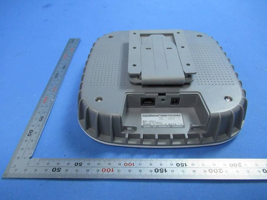
Click to zoom
Application Details
- Equipment Class
- UWB - Ultra Wideband Transmitter
- Date of Grant
- Jul 11, 2020
- Application Purpose
- Original Equipment
- Date of Application
- Jul 11, 2020
- Equipment Note
- UWB Gateway
- Frequency Range
- 6100.00000000 - 6900.00000000
- Country
- China
Documents & Files
Document Text
Text extracted from the exhibit documents filed with the FCC. Open a document above to read the original.
Users Manual
清研讯科(北京)科技有限公司 http://www.social-distancing-contact-tracing.com/ Email:[email protected] Table of Contents 1.Introduction 1.1.Product Description 1.2.Typical Applications 2. Panels 2.1.Front panel of the UWB Gateway 2.2.Rear panel of the UWB Gateway 3. Installation and power supply 3.1.Installation of UWB Gateway 3.2.Power supply 4. Internet connection of UWB Gateway 4.1Network connection 4.2.Network configuration 5. Data collection 6.Important handling information for UWB Gateway 7. Important handling information for UWB Gateway 8. EU Compliance 9. FCC compliance statement 10. Disposal and recycling information for UWB Gateway 11. Limited warranty 12. IP statement 13. Responsibility statement 14. Appendix 1 1 1 2 2 3 4 4 5 6 6 7 8 8 10 11 11 12 13 14 15 16 1.Introduction 1.1.Product Description U3000-t UWB Gateway is designed to collect data from UWB Tags when UWB tags are within 3m and stay for at least 1 second. The collecting process might affect the alarm and recording function of UWB Tag. The collected data will be uploaded to the designated sever, and will be only held by the owner of UWB Gateway and server. 1.2.Typical Applications In typical cases, UWB Gateway is mounted near main entrance, and connected to a designated local server. When a person carries a UWB Tag through the main entrance, if the distance between the UWB Tag and the UWB Gateway is within 3m and stay for more than 1 second, the recorded alarm data in the UWB Tag will be collected by the UWB Gateway, and finally uploaded to the sever. Sever Room Sever Ethernet Cable UWB Gateway 2.Panels 2.1.Front panel of the UWB Gateway Three LED indicators are on the front panel of U3000-t UWB Gateway to indicate its working status. Description 1 Network Link Indicator LED is On: No network link LED is Flushing: Network link is normal. This indicator is reserved for further use. LED is On: No link with the tag LED is Flushing: Tag link is normal Wireless Indicator (reserved) UWB Link Indicator 2 3 21 2.Panels 2.2.Rear panel of the UWB Gateway The rear panel of U3000-t UWB Gateway includes network connector, power supply connector, reset button and label. 3.Installation and power supply 3.1.Installation of UWB Gateway The U3000-t UWB Gateway is generally installed near the entrance, and the installation height is generally 2m. The installation method is as follows: UWB gateway can only effectively cover a distance of 3~5m. It should be installed with care to function normally. You need to pay attention to the following: The UWB Gateway should be installed in the correct posture, face down. The UWB Gateway should not be installed vertically or at an angle. The UWB Gateway should not be blocked by objects. Keep away from obstructions such as weak current bridges, fire pipes, air conditioning pipes and other shelters. Avoid installing the UWB Gateway on top of the ceiling (no matter the material of the ceiling is metalliclike aluminum gussets, or non-metallic, like gypsum boards and glass plates). Keep away from objects that easily cause signal reflection, including large-area metals and large screens. Description 1RJ45 Network Port PoE power input & network transmission multiplexing port. When power is on, use a needle to press this button and hold for 15 seconds and then release. The UWB Gateway will restore the factory settings and restart. DC power input interface, connect to 24VDC/1A adapter. UWB Gateway information. Reset Button DC24V Power Adaptor Port Label Zone 2 3 4 Ceiling installationSuspension installation CEILINGCEILING 43 3.2.Power supply UWB Gateway has two power supply methods: PoE and DC . Power over Ethernet Use Cat 5+ network cable to connect PoE switch(which meets the 802.3af standards) and UWB Gateway. Note that the distance between PoE switch and UWB Gateway should not exceed 80 meters. This method uses a single cable to achieve both power and network connection. DC Power UWB Gateway uses 24VDC/1A adapter for power supply. Please use the original adapter or selected adapter that meets the above specifications. At the same time, use Cat 5+ network cable to connect an ordinary network switch and the UWB Gateway to achieve network connection. 4. Internet connection of UWB Gateway 4.1.Wired network There are two main connection methods between the UWB Gateway and the computer, as shown in Figures 4.1 and 4.2: Network Cable 4.2 Connection via network switch 4.1 Direct connection via network cable Power Cable Server UWB GatewayServer Network Cable Network Cable Network Cable UWB Gateway 5 6 4.2.Network configuration You need the “Social Distancing Contact Tracing Software”to configure the Gateway. Please refer to “Software Installation and Deployment Instructions V1.1”for detailed configuration steps. If you don’t get the software, contact your system administrator for help. Here is the basic Network knowdege of the UWB Gateway. The U3000-t UWB Gateway uses a fixed IP address to access the network and does not support either the DHCP function, nor the network domain name function. The default IP of the UWB Gateway is "192.168.1.X" and the network port number is "48200". The X in IP varies with the ID of the UWB Gateway. You can get the default IP from the label on the packaging box. Before modifying the network settings of the UWB Gateway, you should first modify the IP address of the computer. It is recommended to configure the ·computer's network as: 5.Data Collection The main purpose of U3000-t UWB Gateway is to collect data from UWB Tags. It takes about 1 second for each UWB Tag to upload its alarm records. The effective data collection zone is a circle with a radius of 3m and centered on the UWB Gateway. Please ensure that UWB Tags stay in the collection zone for more than 1 second to ensure the collecting process. During collecting, the alarm function of UWB Tags may be interfered. It will return to normal when leaving the data collection zone. The collected data will be uploaded to the designated server, a…
Text truncated - open the document above for the full version.
External Photos
SGS-CSTC Standards Technical Services Co., Ltd. Shenzhen Branch Page: 1 of 5 Page 1 of 5 External Photos Applicant: Tsingoal (Beijing) Technology Co., Ltd. Address of Applicant: Room 32021, Zhongtai Building, Shuangqing Road No.3, Haidian District, Beijing, China Equipment Under Test (EUT): Product Name: UWB Gateway Model No.: U3000-t SGS-CSTC Standards Technical Services Co., Ltd. Shenzhen Branch Page: 2 of 5 Page 2 of 5 SGS-CSTC Standards Technical Services Co., Ltd. Shenzhen Branch Page: 3 of 5 Page 3 of 5 SGS-CSTC Standards Technical Services Co., Ltd. Shenzhen Branch Page: 4 of 5 Page 4 of 5 SGS-CSTC Standards Technical Services Co., Ltd. Shenzhen Branch Page: 5 of 5 Page 5 of 5 End
ID Label/Location Info
Tsingoal (Beijing) Technology Co., Ltd. Label Location Justification Letter Subject: Label location request for FCC ID: 2AWDCU3000-T Dear Sir or Madam, The device is a UWB Gateway, where it is shown that a permanently affixed Label is not desirable that affect the appearance of the product. To validate the grant of equipment authorization, the FCC ID is attached on power supply port compartment. It is readily viewable at all times of purchase and during normal installation. Thank you in advanced! Best regards. Signature: Printed Name: ethan Zheng Date: 2020-7-2
Internal Photos
SGS-CSTC Standards Technical Services Co., Ltd. Shenzhen Branch P age: 1 of 8 Page 1 of 8 Internal Photos Applicant: T singoal (Beijing) Technology Co., Ltd. Address of Applicant: Room 32021, Zhongtai Building, Shuangqing Road No.3, Haidian District, Beijing, China Equipment Under Test (EUT): Product Name: UWB Gateway Model No.: U3000-t SGS-CSTC Standards Technical Services Co., Ltd. Shenzhen Branch P age: 2 of 8 Page 2 of 8 SGS-CSTC Standards Technical Services Co., Ltd. Shenzhen Branch P age: 3 of 8 Page 3 of 8 Antenna SGS-CSTC Standards Technical Services Co., Ltd. Shenzhen Branch P age: 4 of 8 Page 4 of 8 SGS-CSTC Standards Technical Services Co., Ltd. Shenzhen Branch P age: 5 of 8 Page 5 of 8 SGS-CSTC Standards Technical Services Co., Ltd. Shenzhen Branch P age: 6 of 8 Page 6 of 8 SGS-CSTC Standards Technical Services Co., Ltd. Shenzhen Branch P age: 7 of 8 Page 7 of 8 SGS-CSTC Standards Technical Services Co., Ltd. Shenzhen Branch P age: 8 of 8 Page 8 of 8 End
Test Report
SGS-CSTC Standards Technical Services Co., Ltd. Shenzhen Branch Report No.: SZEM200600523601 Page: 1 of 25 Keny Xu EMC Laboratory Manager TEST REPORT Application No.: SZEM2006005236CR (SHEM2005003838CR) FCC ID: 2AWDCU3000-T Applicant: Tsingoal (Beijing) Technology Co., Ltd. Address of Applicant: Room 32021, Zhongtai Building, Shuangqing Road No.3, Haidian District, Beijing, China Manufacturer: Tsingoal (Beijing) Technology Co., Ltd. Address of Manufacturer: Room 32021, Zhongtai Building, Shuangqing Road No.3, Haidian District, Beijing, China Factory: Beijing Yongshixinyu Electronic Technology Co., Ltd. Address of Factory: Maohua factory, houfengbozuodi Road, Shunyi District, Beijing, China Equipment Under Test (EUT): EUT Name: UWB Gateway Model No.: U3000-t Standard(s) : 47 CFR Part 15, Subpart F Date of Receipt: 2020-05-19 Date of Test: 2020-05-29 to 2020-06-20 Date of Issue: 2020-06-22 Test Result: Pass* * In the configuration tested, the EUT complied with the standards specified above. SGS-CSTC Standards Technical Services Co., Ltd. Shenzhen Branch Report No.: SZEM200600523601 Page: 2 of 25 Revision Record Version Description Date Remark 00 Original 2020-06-22 / Authorized for issue by: Foray Chen /Project Engineer Eric Fu /Reviewer SGS-CSTC Standards Technical Services Co., Ltd. Shenzhen Branch Report No.: SZEM200600523601 Page: 3 of 25 2 Test Summary Test Item Test Requirement Test method Result Antenna Requirement 47 CFR Part 15, Subpart C Section 15.203 & Subpart F Section 15.517 (a)(3) NA PASS Conducted Emissions at AC Power Line (150kHz- 30MHz) 47 CFR Part 15, Subpart C 15.207 ANSI C63.10 (2013) Section 6.2 PASS UWB Bandwidth 47 CFR Part 15, Subpart F Section 15.503 (a) ANSI C63.10 (2013) PASS Dwell Time 47 CFR Part 15, Subpart F Section 15.517 (a)(5) ANSI C63.10 (2013) PASS* Spurious Emissions 47 CFR Part 15, Subpart F Section 15.517 (c)(d)/15.209 ANSI C63.10 (2013) PASS EIRP 47 CFR Part 15, Subpart F Section 15.517 (e) ANSI C63.10 (2013) PASS N/A: Not applicable *The details please refer to section 7.4 SGS-CSTC Standards Technical Services Co., Ltd. Shenzhen Branch Report No.: SZEM200600523601 Page: 4 of 25 3 Contents Page 1 COVER PAGE ............................................................................................................................................. 1 2 TEST SUMMARY ......................................................................................................................................... 3 3 CONTENTS .................................................................................................................................................. 4 4 GENERAL INFORMATION ......................................................................................................................... 5 4.1 DETAILS OF E.U.T. ................................................................................................................................ 5 4.2 DESCRIPTION OF SUPPORT UNITS........................................................................................................... 5 4.3 MEASUREMENT UNCERTAINTY ................................................................................................................ 5 4.4 TEST LOCATION ..................................................................................................................................... 6 4.5 TEST FACILITY ....................................................................................................................................... 6 4.6 DEVIATION FROM STANDARDS ................................................................................................................ 6 4.7 ABNORMALITIES FROM STANDARD CONDITIONS ....................................................................................... 6 5 EQUIPMENT LIST ....................................................................................................................................... 7 6 RADIO SPECTRUM TECHNICAL REQUIREMENT ................................................................................... 9 6.1 ANTENNA REQUIREMENT ........................................................................................................................ 9 7 RADIO SPECTRUM MATTER TEST RESULTS ...................................................................................... 10 7.1 CONDUCTED EMISSIONS AT AC POWER LINE (150KHZ-30MHZ) ............................................................ 10 7.2 RADIATED SPURIOUS EMISSIONS .......................................................................................................... 14 7.3 UWB BANDWIDTH (10DB BANDWIDTH) ................................................................................................. 21 7.4 DWELL TIME ........................................................................................................................................ 23 8 TEST SETUP PHOTOGRAPHS ................................................................................................................ 25 9 EUT CONSTRUCTIONAL DETAILS ......................................................................................................... 25 SGS-CSTC Standards Technical Services Co., Ltd. Shenzhen Branch Report No.: SZEM200600523601 Page: 5 of 25 4 General Information 4.1 Details of E.U.T. Power supply: DC 24V 1A by adapter or 48V 0.5A by POE Adapter: Model:KA2401A-2401000US Input:100-240V~50/60Hz Output:24V 1A Test voltage: Product category: AC 120V/60Hz Indoor UWB system Antenna Gain: 2dBi Antenna Type: PCB antenna Modulation Type: BPM-BPSK Number of Channels: 1 Frequency range: 6.1GHz to 6.9GHz 4.2 Description of Support Units The EUT has been tested as an independent unit. 4.3 Measurement Uncertainty No. Item Measurement Uncertainty 1 Radio Frequency ± 7.25 x 10 -8 2 Duty cycle ± 0.37% 3 Occupied Bandwidth ± 3% 4 Conduction emission ± 3.0dB (150kHz to 30MHz) 5 RF conducted power ± 0.75dB 6 RF power density ± 2.84dB 7 Cond…
Text truncated - open the document above for the full version.
Test Setup Photos
SGS-CSTC Standards Technical Services Co., Ltd. Shenzhen Branch Page: 1 of 4 Page 1 of 4 Test Setup Photos-FCC Applicant: Tsingoal (Beijing) Technology Co., Ltd. Address of Applicant: Room 32021, Zhongtai Building, Shuangqing Road No.3, Haidian District, Beijing, China Equipment Under Test (EUT): Product Name: UWB Gateway Model No.: U3000-t SGS-CSTC Standards Technical Services Co., Ltd. Shenzhen Branch Page: 2 of 4 Page 2 of 4 1 Contents Page 1 CONTENTS .......................................................................................................... 2 2 EQUIPMENT UNDER TEST PICTURES ......................................................... 3 2.1 Conducted Emissions at AC Power Line (150kHz-30MHz) Test Setup ........ 3 2.2 Radiated Emission Test Setup ...................................................................... 3 SGS-CSTC Standards Technical Services Co., Ltd. Shenzhen Branch Page: 3 of 4 Page 3 of 4 2 EQUIPMENT UNDER TEST PICTURES 2.1 Conducted Emissions at AC Power Line (150kHz-30MHz) Test Setup 2.2 Radiated Emission Test Setup 30MHz to 1GHz SGS-CSTC Standards Technical Services Co., Ltd. Shenzhen Branch Page: 4 of 4 Page 4 of 4 Above 1GHz Zoom: End
Contact Information
Applicant
ethan Zheng
Technical Contact
SGS-CSTC Standards Technical Services Co., LtdParlam Zhan
[email protected]86 21 61915666
588 West Jindu Road, Xinqiao, Songjiang · ShangHai · China
Test Firm
SGS-CSTC Standards Technical Services Co.,Ltd.Lola Yuan
[email protected]+86 (0)21 6191 5609
Technical Specifications
| # | Rule Parts | Frequency Range | Power Output |
|---|---|---|---|
| 1 | 15F | 6.10 GHz - 6.90 GHz | - |
Other Applications from Tsingoal (Beijing) Technology Co., Ltd

2AWDCTR1000-D
May 18, 2021TICTAG
Equipment Class
UWB - Ultra Wideband Transmitter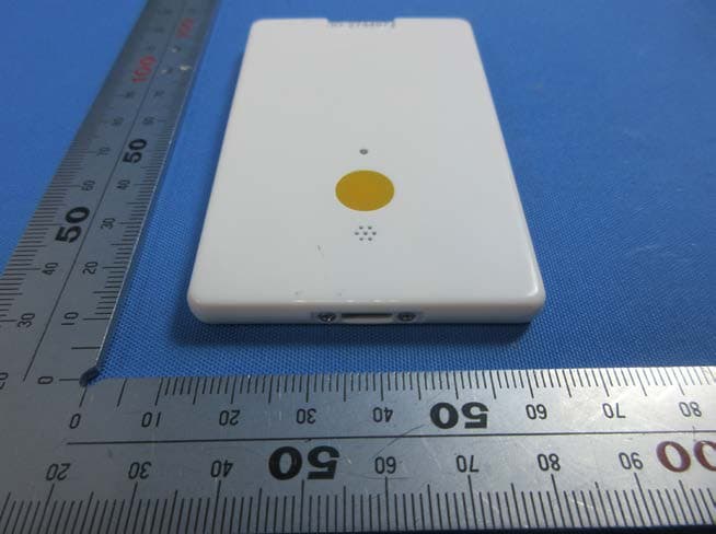
2AWDCTB1000-G
Jun 10, 2020UWB Tag
Equipment Class
UWB - Ultra Wideband Transmitter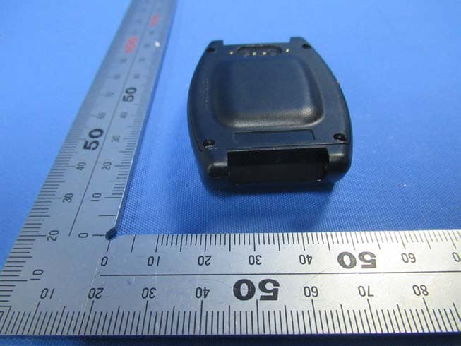
2AWDCTB1000-W
Jun 10, 2020UWB Tag
Equipment Class
UWB - Ultra Wideband Transmitter