2AWG9-EVERESTIPQ4018 High Power Wireless Router/AP
WiFiRanger, A LinOra Company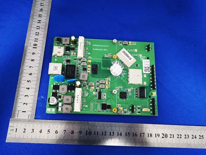
Click to zoom
Application Details
- Equipment Class
- NII - Unlicensed National Information Infrastructure TX
- Date of Grant
- Jun 08, 2020
- Application Purpose
- Original Equipment
- Date of Application
- Jun 08, 2020
- Equipment Note
- IPQ4018 High Power Wireless Router/AP
- Frequency Range
- 5745.00000000 - 5825.00000000
- Company
- WiFiRanger, A LinOra Company
- Country
- United States
Documents & Files
Document Text
Text extracted from the exhibit documents filed with the FCC. Open a document above to read the original.
Users Manual
WiFiRanger, A LinOra Company Everest V1.1 1 IPQ4018 High Power Wireless Router/AP Model:Everest V1.1 Description: The Everest V1.1 processor board is a dual-band 11AC Wave-2 wireless Gigabit enterprise router. It has built-in Qualcomm enterprise IPQ4018 CPU, large flash and high speed memory, strong data processing capability and support dual frequency concurrency,it is a reliable and flexiblenetworking deviceproviding security, and speed for enterprises. Features: 1. Using Qualcomm 4-core ARM Cortex-A7 IPQ4018 cpufrequency 600Mhz 2. Large memory and large storage design to meet different needs 3. Meet the standard of IEEE 802.11n, IEEE 802.11g/b/, 11AC multi-wave-2 IEEE 802.3/3u 4. High power design, 2.4G adopts SKY85309, 5.8G adopts SKY85728 5. Support 11AC, wireless can reach up to 1200M, to meet various application scenarios 6. Support PPPoE, dynamic IP, static IP and other broadband access methods 7. Support 2.0/3.0USB interface for fast shared mobile storage network 8. Industrial grade design, the power supply and network port are support surge 4KV, and electrostatic 8KV which tested in lab 9. Hardware watchdog design, working unobstructe in a whole day 10. Support Open-Wrt system, which is convenient for customers to develop by themselves Specification Protocol IEEE802.11N/G/B/AC Chipset ARM Cortex-A7 IPQ4018,CPU main frequency is 600Mhz RAM Defualt DDR3:256MB, Max. 256MB FLASH Defualt 32MB, Max. 128MB Wireless Speed Rate 2.4G:2T2R:300Mbps 5.8G:2T2R:866Mbps Working Frequency 2.4Ghz/5.8Ghz Interface Supports 1 10/100/1000M self-adaption WAN with auto flip (Auto MDI/MDIX) Supports 1 10/100M/1000 self-adaption LANs and auto flip (Auto MDI/MDIX) Support 1 2.0 USB Support 1 3.0USB Support 2 MINI PCIE (usb 2.0) Max. Power Consumption <15W Dimension 147X107X19MM(LXWXH) Working Environment Working Temperature: -10 ° C to 75 ° C Storage Temperature: -40 ° C to 100 ° C Working Humidity: 10% to 90% RH does not condense Storage Humidity: 5% to 90% RH does not condense RF(Typical) 11A HT20 11A HT40 11A HT80 MCS0/10 23dB±2dB MCS0/10 23dB±2dB MCS0/10 23dB±2dB MCS1/11 23dB±2dB MCS1/11 23dB±2dB MCS1/11 23dB±2dB WiFiRanger, A LinOra Company Everest V1.1 2 MCS2/12 23dB±2dB MCS2/12 23dB±2dB MCS2/12 23dB±2dB MCS3/13 22dB±2dB MCS3/13 22dB±2dB MCS3/13 22dB±2dB MCS4/14 22dB±2dB MCS4/14 22dB±2dB MCS4/14 22dB±2dB MCS5/15 22dB±2dB MCS5/15 22dB±2dB MCS5/15 22dB±2dB MCS6/16 21dB±2dB MCS6/16 21dB±2dB MCS6/16 21dB±2dB MCS7/17 20dB±2dB MCS7/17 20dB±2dB MCS7/17 20dB±2dB MCS8/18 19dB±2dB MCS8/18 19dB±2dB MCS8/18 19dB±2dB MCS9/19 18dB±2dB MCS9/19 18dB±2dB Sensitivity 11A HT20 11A HT40 11A HT80 MCS0/10≤-82 MCS0/10≤-79 MCS0/10≤-76 MCS1/11≤-79 MCS1/11≤-76 MCS1/11≤-73 MCS2/12≤-77 MCS2/12≤-74 MCS2/12≤-71 MCS3/13≤-74 MCS3/13≤-71 MCS3/13≤-68 MCS4/14≤-70 MCS4/14≤-67 MCS4/14≤-64 MCS5/15≤-66 MCS5/15≤-63 MCS5/15≤-60 MCS6/16≤-65 MCS6/16≤-62 MCS6/16≤-59 MCS7/17≤-64 MCS7/17≤-61 MCS7/17≤-58 MCS8/18≤-59 MCS8/18≤-56 MCS8/18≤-53 MCS9/19≤-54 MCS9/19≤-51 Wireless Security Wireless security function switch; 64/128/152 bit WEP encryption; WPA-PSK/WPA2-PSK, WPA/WPA2 security mechanism; WPS fast security settings Software Features Support AP, router, relay, 4G function, etc. Support VPN security tunneling function, Support dynamic routing and static routing Convenient WEB configuration Wireless settings and encryption Support telnet management, easy to use console shell interactive environment Support multiple dialing methods: automatic allocation, specify IP, specify local peer IP, ppoe Support local software upgrade; support configuration export import, and web online update firmware Support operating system Windows XP/7/8/9/10/Linux WiFiRanger, A LinOra Company Everest V1.1 3 Product(Top) Product(Bottom) WiFiRanger, A LinOra Company Everest V1.1 4 Product Structure Product Definition WiFiRanger, A LinOra Company Everest V1.1 5 Product Application: Intelligent Transportation: 1. HD electronic bayonet application 2. HD electronic police application 3. Road wireless video Surveillance Vehicle monitoring: 1. Bus wireless video surveillance 2. Taxi video surveillance 3. Bus video surveillance Security monitoring: 1. Security wireless mobile detection system 2. Security wireless video surveillance Industrial monitoring: 1. Site wireless video surveillance 2. Industrial big data transmission 3 Remote crane monitoring and management 4. Elevator remote monitoring Financial industry: 1. Wireless ATM self-service terminal 2. Coal mine tax monitoring system 3. Wireless POS application Power industry: 1. Substation 3G video surveillance 2. Transformer remote monitoring management 3. Power line video surveillance Environmental protection industry: 1.3G noise monitoring system 2. Wireless monitoring system for pollution sources 3. Wireless environmental monitoring system Water conservancy industry: 1. Reservoir remote monitoring system 2. Water environment comprehensive monitoring system Other industries: 1. Municipal engineering 2. Petroleum monitoring 3. Agricultural applications 4. Wireless WIFI applications WiFiRanger, A LinOra Company Everest V1.1 6 FCC WARNING FCC Caution: Any changes or modifications not expressly approved by the party responsible for compliance could void the user's authority to operate this equipment. This device complies with Part 15 of the FCC Rules. Operation is subject to the following two conditions: (1) This device may not cause harmful interference, and (2) this device must accept any interference received, including interference that may cause undesired operation. This device and its antenna(s) must not be co-located or operating in conjunction with any other antenna or transmitter. 15.105 Information to the user. (b) For a Class B digital device or peripheral, the instructions furnished the user shall include the following or similar statement, placed in a prominent location in the text of the manual: Note: This equipment has been tested and found to comply with the limits for a Class B digital device, pursuant to p…
Text truncated - open the document above for the full version.
Cover Letter(s)
WiFiRanger, A LinOra Company FCC Software Configuration Control Declaration Date: June 5, 2020 Federal Communications Commission 7435 Oakland Mills Road Columbia, MD 21046 USA Attn: OET Dept. Product/ Model Number: IPQ4018 High Power Wireless Router/AP/Everest V1.1 Regarding FCC Country Code Selection guidelines identified in KDB 594280. “All applications for equipment authorization for transmitters that can have radio parameters, or other technical parameters, reported to the Commission set by software must have an attestation indicating that no third party will have software, or configuration control, to program the device out of compliance of the technical rules under which it has been certified.” We declare that no third party will have software, or configuration control, to program the device out of compliance of the technical rules under which it has been certified. Name:Kelly Hogan Date: 2020/06/05 Title: Manger Signatureof applicant FCC Software Configuration Control Declaration Rev1.1_sig
Cover Letter(s)
WiFiRanger, A LinOra Company Agent Authorization Company:WiFiRanger, A LinOra Company Address:943 W Overland Road, Meridian, ID 83642 USA Product Name: IPQ4018 High Power Wireless Router/AP Model Number(s ): Everest V1.1 Product Description: IPQ4018 High Power Wireless Router/AP We authorize MiCOM Labs Inc., 575 Boulder Court, Pleasanton, California 94566, USA, to act on our behalf on all matters concerning the certification of above named equipment. We declare that MiCOM Labs Inc. is allowed to forward all information related to the approval and certification of equipment to the regulatory agencies as required and to discuss any issues concerning the approval application. Any and all acts carried out by MiCOM Labs on our behalf shall have the same effect as acts of our own. Signature: Date: 2020/06/03 Name: Kelly Hogan Title: Manager Company: WiFiRanger, A LinOra Company
Cover Letter(s)
WiFiRanger, A LinOra Company Federal Communications Commission Equipment Authorization Division 7435 Oakland Mills Road Columbia, MD 21046 USA Date: 06/05/2020 Subject; Modular Transmitter Application Company name: WiFiRanger, A LinOra Company FCC ID: 2AWG9-EVEREST Dear Sir/Madam, This letter includes the FCC application requirements for Modular Transmitter Approval Request for;- FCC KDB 996369 D01 ‘Module Certification Guide v02; and FCC KDB 996369 D03 OEM Manual v01 In accordance with 47CFR 15.212 Modular Transmitters and KDB 996369 D01 ‘Module Equip Auth Guide v02’. FCC ID 2AWG9-EVEREST has been examined against the following requirements. Requirement per 15.212 and KDB 996369 D01 Explanation from Grantee (do not write yes/no, but explain why product complies/how it is achieved) The radio elements must have the radio frequency circuitry shielded. Physical components and tuning capacitor(s) may be located external to the shield, but must be on the module assembly. Yes, It has a shield The module must have buffered modulation/data inputs to ensure that the device will comply with Part 15 requirements with any type of input signal. Yes, The modular data inputs are buffered through log or microcontroller connections. All modulation and data inputs are buffered by circuitry on the transmitter chip. The module must contain power supply regulation on the module. Yes, Power supply regulation is provided by circuitry on the CPU chip. The module must contain a permanently attached antenna, or contain a unique antenna connector, and be marketed and operated only with specific antenna(s), per §§ 15.203, 15.204(b), 15.204(c), 15.212(a), 2.929(b). The EUT meet the FCC antenna requirements, the modular with a special joint antenna connector. The module must demonstrate compliance in a stand-alone configuration. Yes, The EUT is can transmitting Stand-alone, please refer the test setup photos. The module must be labeled with its permanently affixed FCC ID label, or use an electronic display (see KDB Publication 784748). The module is labeled with its permanently affixed FCC ID label. The label position is clearly indicated. Please refer to label & label location information. The module must comply with all specific rules applicable to the transmitter, including all the conditions provided in the integration instructions by the grantee. Yes, The EUT is full compliant with FCC rules, please refer the details in user manual. FCC Modular Approval Request Rev 3.0 WiFiRanger, A LinOra Company The module must comply with RF exposure requirements This module is complies with FCC CFR 47 part 2.1091 and FCC KDB 447498 D01 General RF Exposure Guidance v06 limit , Please refer RF exposure report. Integration Instructions for host product manufacturers The following items are submitted in support of application for Modular Transmitter FCC ID as noted above as required by the FCC KDB 996369 D03 OEM Manual v01. These items are provided as integration instructions for host product manufacturers (e.g., OEM instruction manual) to use when integrating a module in a host product. Any requirements that are not applicable to the Module are as indicated below. Summary of requirements and Checklist. Refer to the KDB for description of the complete requirements; KDB Ref Sect Requirements of KDB 996369 D03 User Manual Page Number reference 2.2 List of applicable FCC rules Page 7 2.3 Summarize the specific operational use conditions Page 7 2.4 Limited module procedures Page 7 2.5 Trace antenna designs Page 8 2.6 RF exposure considerations Page 8 2.7 Antennas Page 9 2.8 Label and compliance information Page 9 2.9 Information on test modes and additional testing requirements Page 9 2.10 Additional testing, Part 15 Subpart B disclaimer Page 9 Name: Kelly Hogan Date: 06/05/2020 Title: Manager Signature of applicant: FCC Modular Approval Request Rev 3.0
Cover Letter(s)
WiFiRanger, A LinOra Company Office of Engineering Technology Federal Communications Commission 7435 Oakland Mills Road Columbia, MD 21046 USA Date: 2020/06/03 Subject; Request for Confidentiality FCC ID: 2AWG9-EVEREST To Whom It May Concern, Pursuant to the provisions of the Commission’s rules Title 47 Sections §0.457 and §0.459, we are requesting the Commission to withhold the following attachment(s) as confidential documents from public disclosure indefinitely. These documents contain detailed system and equipment descriptions and are considered as proprietary information in operation of the equipment. The public disclosure of these documents might be harmful to our company and would give competitors an unfair advantage in the market. Schematic Diagram Block Diagram Operational Description FCC Software Security Requirements for UNII devices In additional to above mentioned documents, in order to comply with the marketing regulations in Title 47 CFR §2.803 and the importation rules in Title 47 CFR §2.1204, while ensuring that business sensitive information remains confidential until the actual marketing of newly authorized devices, we request Short Term Confidentiality of the following attachment(s); User Manual For 45 days, pursuant to Public Notice DA 04-1705. OR For 180 dayspursuantto KDB 726920 D01. It is our understanding that all measurement test reports, FCC ID label format and correspondence during the certification review process cannot be granted as confidential documents and this information will be available for public review once the grant of equipment authorization is issued. Sincerely, Signature: Name:Kelly Hogan Title: Manager
Cover Letter(s)
WiFiRanger, A LinOra Company Model Difference Product description:IPQ4018 High Power Wireless Router/AP Model name: Everest V1.1 YN-HWR1200C1 Trade Name: N/A FCC ID: 2AWG9-EVEREST All the model are the same circuit and RF module, except model names. Regards Sincerely Client’s signature: Client’s name / title :Kelly Hogan/Manager Contact information / address:943 W Overland Road, Meridian, ID 83642 USA
External Photos
External Photos 5G ANT 2.4GANT
ID Label/Location Info
Label & label location Model: Everest V1.1 FCC ID: 2AWG9-EVEREST
Internal Photos
Internal Photos
RF Exposure Info
FCC §15.247 (i), §2.1091 – RF Exposure FCC ID: 2AWG9-EVEREST Applied procedures / limit According to FCC §15.247(i) and §1.1307(b)(1), systems operating under the provisions of this section shall be operated in a manner that ensures that the public is not exposed to radio frequency energy level in excess of the Commission’s guidelines. Limits for Occupational / Controlled Exposure Frequency Range (MHz) Electric Field Strength (E) (V/m) Magnetic Field Strength (H) (A/m) Power Density (S) (mW/ cm 2 ) Averaging Time |E| 2 ,|H| 2 or S (minutes) 0.3-3.0 614 1.63 (100)* 6 3.0-30 1842 / f 4.89 / f (900 / f)* 6 30-300 61.4 0.163 1.0 6 300-1500 F/300 6 1500-100,000 5 6 Note: ƒ is frequency in MHz * = Power density limit is applicable at frequencies greater than 100 MHz Limits for General Population / Uncontrolled Exposure Frequency Range (MHz) Electric Field Strength (E) (V/m) Magnetic Field Strength (H) (A/m) Power Density (S) (mW/ cm 2 ) Averaging Time |E| 2 ,|H| 2 or S (minutes) 0.3-1.34 614 1.63 (100)* 30 1.34-30 824/f 2.19/f (180/f)* 30 30-300 27.5 0.073 0.2 30 300-1500 F/1500 30 1500-100,000 1.0 30 Note: f = frequency in MHz * = Plane-wave equivalent power density MPE PREDICTION Predication of MPE limit at a given distance, Equation from OET Bulletin 65, Edition 97-01 Where: S = power density P = power input to antenna G = power gain of the antenna in the direction of interest relative to an isotropic radiator R = distance to the center of radiation of the antenna, R=0.2m TEST RESULTS For the Max simultaneous transmission MPE Tune up Produce power Maximu m peak output power (dBm) Output power to antenna (mW) Antenna Gain (numeric) Power Density (S) (mW/ cm2) Limit (mW / cm2 ) Result 802.11 B/G/N 21±1 22 158.489 3.162 (5dBi) 0.0997 1 Pass 802.11 U- NII-1 17±1 18 63.096 3.162 (5dBi) 0.0397 1 Pass 802.11 U- NII-3 23±1 24 251.189 3.162 (5dBi) 0.1581 1 Pass Evaluation mode Power Density/Limit Sum of the MPE rate Limit Result 802.11 B/G/N 0.0997 0.2578 1 Pass 802.11 U-NII 0.1581
Test Report
Shenzhen BCTC Testing Co., Ltd. Report No.: BCTC2005000815E FCC Part 15E Test Report FCC ID: 2AWG9-EVEREST Product Name: IPQ4018 High Power Wireless Router/AP Trademark: N/A Model Name : Everest V1.1 YN-HWR1200C1 Prepared For : WiFiRanger, A LinOra Company Address : 943 W Overland Road, Meridian, ID 83642 USA Prepared By : Shenzhen BCTC Testing Co., Ltd. Address : BCTC Building & 1-2F, East of B Building, Pengzhou Industrial, Fuyuan 1st Road, Qiaotou Community, Fuyong Street, Bao’an District, Shenzhen, China Test Date: May 15, 2020 – May 25, 2020 Date of Report : May 25, 2020 Report No.: BCTC2005000815E Te s t Report Tel: 400-788-9558 Web: https://www.bctc-lab.com BCTC/RF-EMC-0 07 Ver.:A.0 Page 1 of 121 Shenzhen BCTC Testing Co., Ltd. Report No.: BCTC2005000815E TEST RESULT CERTIFICATION Applicant’s name ................. : WiFiRanger, A LinOra Company Address ................................. : 943 W Overland Road, Meridian, ID 83642 USA Manufacture's Name ............ : Shenzhen Yinuo-Link Technology Co., Ltd Address ................................. : A201, 2/F, Xinfa East Road No. 12, Xinqiao, Baoan, Shenzhen, China Product description Product name ........................... : IPQ4018 High Power Wireless Router/AP Trademark ................................. : N/A Model and/or type reference : Everest V1.1 YN-HWR1200C1 Standards ............................. : FCC Part15 15.407 ANSI C63.10-2013 KDB 662911 D01 v02r01 KDB 789033 D02 v02r01 This device described above has been tested by BCTC, and the test results show that the equipment under test (EUT) is in compliance with the FCC requirements. And it is applicable only to the tested sample identified in the report. This report shall not be reproduced except in full, without the written approval of BCTC, this document may be altered or revised by BCTC, personal only, and shall be noted in the revision of the document. Prepared by(Engineer): Bin Mei Reviewer(Supervisor): Eric Yang Approved(Manager): Zero Zhou Te s t Report Tel: 400-788-9558 Web: https://www.bctc-lab.com BCTC/RF-EMC-0 07 Ver.:A.0 Page 2 of 121 Shenzhen BCTC Testing Co., Ltd. Report No.: BCTC2005000815E Table of Contents Page 1 . SUMMARY OF TEST RESULTS 6 1.1 TEST FACILITY 7 1.2 MEASUREMENT UNCERTAINTY 7 2 . GENERAL INFORMATION 8 2.1 GENERAL DESCRIPTION OF EUT 8 2.2 DESCRIPTION OF TEST MODES 11 2.3 BLOCK DIGRAM SHOWING THE CONFIGURATION OF SYSTEM TESTED 12 2.4 DESCRIPTION OF SUPPORT UNITS(CONDUCTED MODE) 12 2.5 EQUIPMENTS LIST FOR ALL TEST ITEMS 13 3 . EMC EMISSION TEST 15 3.1 CONDUCTED EMISSION MEASUREMENT 15 3.1.1 POWER LINE CONDUCTED EMISSION LIMITS 15 3.1.2 TEST PROCEDURE 16 3.1.3 DEVIATION FROM TEST STANDARD 16 3.1.4 TEST SETUP 16 3.1.5 EUT OPERATING CONDITIONS 16 3.1.6 TEST RESULT 17 3.2 RADIATED EMISSION MEASUREMENT 19 3.2.1 APPLICABLE STANDARD 19 3.2.2 CONFORMANCE LIMIT 19 3.2.3 MEASURING INSTRUMENTS 19 3.2.4 TEST CONFIGURATION 20 3.2.5 TEST PROCEDURE 21 3.2.6 TEST RESULTS (9KHZ – 30 MHZ) 22 3.2.7 TEST RESULTS (30MHZ – 1GHZ) 23 3.2.8 TEST RESULTS (1GHZ-40GHZ) 25 4 . POWER SPECTRAL DENSITY TEST 37 4.1 APPLIED PROCEDURES / LIMIT 37 4.2 TEST PROCEDURE 38 4.3 DEVIATION FROM STANDARD 38 4.4 TEST SETUP 38 4.5 EUT OPERATION CONDITIONS 38 4.6 TEST RESULTS 39 5 . 26DB & 6DB & 99% EMISSION BANDWIDTH 47 5.1 APPLIED PROCEDURES / LIMIT 47 Te s t Report Tel: 400-788-9558 Web: https://www.bctc-lab.com BCTC/RF-EMC-0 07 Ver.:A.0 Page 3 of 121 Shenzhen BCTC Testing Co., Ltd. Report No.: BCTC2005000815E Table of Contents Page 5.2 TEST PROCEDURE 47 5.3 EUT OPERATION CONDITIONS 48 5.4 TEST RESULTS 49 6 . MAXIMUM CONDUCTED OUTPUT POWER 68 6.1 PPLIED PROCEDURES / LIMIT 68 6.2 TEST PROCEDURE 68 6.3 DEVIATION FROM STANDARD 70 6.4 TEST SETUP 70 6.5 EUT OPERATION CONDITIONS 70 6.6 TEST RESULTS 71 7 . OUT OF BAND EMISSIONS 73 7.1 APPLICABLE STANDARD 73 7.2 TEST PROCEDURE 73 7.3 DEVIATION FROM STANDARD 73 7.4 TEST SETUP 73 7.5 EUT OPERATION CONDITIONS 74 7.6 TEST RESULTS 75 8.SPURIOUS RF CONDUCTED EMISSIONS 94 8.1CONFORMANCE LIMIT 94 8.2MEASURING INSTRUMENTS 94 8.3TEST SETUP 94 8.4TEST PROCEDURE 94 8.5TEST RESULTS 94 9. FREQUENCY STABILITY MEASUREMENT 109 9.1 LIMIT 109 9.2 TEST PROCEDURES 109 9.3 TEST SETUP LAYOUT 109 9.4 EUT OPERATION DURING TEST 109 9.5 TEST RESULTS 110 10. ANTENNA REQUIREMENT 116 10.1 STANDARD REQUIREMENT 116 10.2 EUT ANTENNA 116 11. EUT TEST PHOTO 117 12. EUT PHOTO 120 Te s t Report Tel: 400-788-9558 Web: https://www.bctc-lab.com BCTC/RF-EMC-0 07 Ver.:A.0 Page 4 of 121 Shenzhen BCTC Testing Co., Ltd. Report No.: BCTC2005000815E Revision History Report No. Version Description Issued Date BCTC2005000815E Rev.01 Initial issue of report May 25, 2020 Te s t Report Tel: 400-788-9558 Web: https://www.bctc-lab.com BCTC/RF-EMC-0 07 Ver.:A.0 Page 5 of 121 Shenzhen BCTC Testing Co., Ltd. Report No.: BCTC2005000815E 1. SUMMARY OF TEST RESULTS Test procedures according to the technical standards: FCC Part15 (15.407) , Subpart E Standard Section Test Item Judgment Remark 15.209(a), 15.407 (b)(1) 15.407 (b)(4) 15.407 (b)(6) Spurious Radiated Emissions PASS 15.207 Conducted Emission PASS 15.407 (a)(5) 15.1049 26 dB and 99% Emission Bandwidth PASS 15.407(e) Minimum 6 dB bandwidth PASS 15.407 (a)(1) 15.407 (a)(3) Maximum Conducted Output Power PASS 2.1051, 15.407(b)(1) 15.407(b)(4) Band Edge PASS 15.407 (a)(1) 15.407 (a)(3) Power Spectral Density PASS 2.1051, 15.407(b) Spurious Emissions at Antenna Terminals PASS 15.407(g) Frequency Stability Measurement PASS 15.203 Antenna Requirement PASS NOTE: (1)” N/A” denotes test is not applicable in this Test Report Te s t Report Tel: 400-788-9558 Web: https://www.bctc-lab.com BCTC/RF-EMC-0 07 Ver.:A.0 Page 6 of 121 Shenzhen BCTC Testing Co., Ltd. Report No.: BCTC2005000815E 1.1 TEST FACILITY Shenzhen BCTC Testing Co., Ltd. Add. : BCTC Building & 1-2F, East of B Building, Pengzhou Industrial, Fuyuan 1st Road, Qiaotou Community, Fuyong Street, Bao’an District, Shenzhen, China FCC Te st Firm Registration Number: 712850 IC Registered No.: 23583 1.2 ME…
Text truncated - open the document above for the full version.
Test Report
Shenzhen BCTC Testing Co., Ltd. Report No.: BCTC2005000815E Mode: 802.11n-HT40 5755 MHz 6dB bandwidth 5755 MHz 99% bandwidth 5795 MHz 6dB bandwidth Te s t Report Tel: 400-788-9558 Web: https://www.bctc-lab.com BCTC/RF-EMC-0 07 Ver.:A.0 Page 61 of 121 Shenzhen BCTC Testing Co., Ltd. Report No.: BCTC2005000815E 5795 MHz 99% bandwidth Te s t Report Tel: 400-788-9558 Web: https://www.bctc-lab.com BCTC/RF-EMC-0 07 Ver.:A.0 Page 62 of 121 Shenzhen BCTC Testing Co., Ltd. Report No.: BCTC2005000815E Mode: 802.11ac-HT20 5745MHz 6dB bandwidth 5745MHz 99% bandwidth 5785MHz 6dB bandwidth Te s t Report Tel: 400-788-9558 Web: https://www.bctc-lab.com BCTC/RF-EMC-0 07 Ver.:A.0 Page 63 of 121 Shenzhen BCTC Testing Co., Ltd. Report No.: BCTC2005000815E 5785MHz 99% bandwidth 5825MHz 6dB bandwidth 5825MHz 99% bandwidth Te s t Report Tel: 400-788-9558 Web: https://www.bctc-lab.com BCTC/RF-EMC-0 07 Ver.:A.0 Page 64 of 121 Shenzhen BCTC Testing Co., Ltd. Report No.: BCTC2005000815E Mode: 802.11ac-HT40 5755 MHz 6dB bandwidth 5755 MHz 99% bandwidth 5795 MHz 6dB bandwidth Te s t Report Tel: 400-788-9558 Web: https://www.bctc-lab.com BCTC/RF-EMC-0 07 Ver.:A.0 Page 65 of 121 Shenzhen BCTC Testing Co., Ltd. Report No.: BCTC2005000815E 5795 MHz 99% bandwidth Te s t Report Tel: 400-788-9558 Web: https://www.bctc-lab.com BCTC/RF-EMC-0 07 Ver.:A.0 Page 66 of 121 Shenzhen BCTC Testing Co., Ltd. Report No.: BCTC2005000815E Mode: 802.11ac-HT80 5755 MHz 6dB bandwidth 5755 MHz 99% bandwidth Te s t Report Tel: 400-788-9558 Web: https://www.bctc-lab.com BCTC/RF-EMC-0 07 Ver.:A.0 Page 67 of 121 Shenzhen BCTC Testing Co., Ltd. Report No.: BCTC2005000815E 6. MAXIMUM CONDUCTED OUTPUT POWER 6.1 PPLIED PROCEDURES / LIMIT According to FCC §15.407 The maximum conduced output power should not exceed: Frequency Band(MHz) Limit 5150~5250 1W 5725~5850 1W 6.2 TEST PROCEDURE . Maximum conducted output power may be measured using a spectrum analyzer/EMI receiver or an RF power meter. 1. Device Configuration If possible, configure or modify the operation of the EUT so that it transmits continuously at its maximum power control level (see section II.B.). a) The intent is to test at 100 percent duty cycle; however a small reduction in duty cycle (to no lower than 98 percent) is permitted if required by the EUT for amplitude control purposes. Manufacturers are expected to provide software to the test lab to permit such continuous operation. b) If continuous transmission (or at least 98 percent duty cycle) cannot be achieved due to hardware limitations (e.g., overheating), the EUT shall be operated at its maximum power control level with the transmit duration as long as possible and the duty cycle as high as possible. 2. Measurement using a Spectrum Analyzer or EMI Receiver (SA) Measurement of maximum conducted output power using a spectrum analyzer requires integrating the spectrum across a frequency span that encompasses, at a minimum, either the EBW or the 99-percent occupied bandwidth of the signal.1 However, the EBW must be used to determine bandwidth dependent limits on maximum conducted output power in accordance with § 15.407(a). Te s t Report Tel: 400-788-9558 Web: https://www.bctc-lab.com BCTC/RF-EMC-0 07 Ver.:A.0 Page 68 of 121 Shenzhen BCTC Testing Co., Ltd. Report No.: BCTC2005000815E a) The test method shall be selected as follows: (i) Method SA-1 or SA-1 Alternative (averaging with the EUT transmitting at full power throughout each sweep) shall be applied if either of the following conditions can be satisfied: • The EUT transmits continuously (or with a duty cycle ≥ 98 percent). • Sweep triggering or gating can be implemented in a way that the device transmits at the maximum power control level throughout the duration of each of the instrument sweeps to be averaged. This condition can generally be achieved by trig gering the instrument’s sweep if the duration of the sweep (with the analyzer configured as in Method SA-1, below) is equal to or shorter than the duration T of each transmission from the EUT and if those transmissions exhibit full power throughout their durations. (ii) Method SA-2 or SA-2 Alternative (averaging across on and off times of the EUT transmissions, followed by duty cycle correction) shall be applied if the conditions of (i) cannot be achieved and the transmissions exhibit a constant duty cycle during the measurement duration. Duty cycle will be considered to be constant if variations are less than ± 2 percent. (iii) Method SA-3 (RMS detection with max hold) or SA-3 Alternative (reduced VBW with max hold) shall be applied if the conditions of (i) and (ii) cannot be achieved. b) Method SA-1 (trace averaging with the EUT transmitting at full power throughout each sweep): (i) Set span to encompass the entire emission bandwidth (EBW) (or, alternatively, the entire 99% occupied bandwidth) of the signal. (ii) Set RBW = 1 MHz. (iii) Set VBW ≥ 3 MHz. (iv) Number of points in sweep ≥ 2 Span / RBW. (This ensures that bin-to-bin spacing is ≤ RBW/2, so that narrowband signals are not lost between frequency bins.) (v) Sweep time = auto. (vi) Detector = RMS (i.e., power averaging), if available. Otherwise, use sample detector mode. (vii) If transmit duty cycle < 98 percent, use a video trigger with the trigger level set to enable triggering only on full power pulses. Transmitter must operate at maximum power control level for the entire duration of every sweep. If the EUT transmits continuously (i.e., with no off intervals) or at duty cycle ≥ 98 percent, and if each transmission is entirely at the maximum power control level, then the trigger shall be set to “free run”. (viii) Trace average at least 100 traces in power averaging (i.e., RMS) mode. (ix) Compute power by integrating the spectrum across the EBW (or, alternatively, the entire 99% occupied bandwidth) of the signal using the instrument’s band power measurement function with band limits set equal to the EBW (or occupied bandwidth) band edges. If the instrument doe…
Text truncated - open the document above for the full version.
Test Report
Shenzhen BCTC Testing Co., Ltd. Report No.: BCTC2005000815E 802.11n(HT20) For the frequency band 5745-5825MHz Low Channel Te s t Report Tel: 400-788-9558 Web: https://www.bctc-lab.com BCTC/RF-EMC-0 07 Ver.:A.0 Page 91 of 121 Shenzhen BCTC Testing Co., Ltd. Report No.: BCTC2005000815E Middle Channel Te s t Report Tel: 400-788-9558 Web: https://www.bctc-lab.com BCTC/RF-EMC-0 07 Ver.:A.0 Page 92 of 121 Shenzhen BCTC Testing Co., Ltd. Report No.: BCTC2005000815E High Channel Note: 1. This EUT was tested in 802.11a/n/ac(HT20), n/ac(HT40), ac(HT80) mode and 802.11n(HT20) the worst case position data was reported. Te s t Report Tel: 400-788-9558 Web: https://www.bctc-lab.com BCTC/RF-EMC-0 07 Ver.:A.0 Page 93 of 121 Shenzhen BCTC Testing Co., Ltd. Report No.: BCTC2005000815E 8.SPURIOUS RF CONDUCTED EMISSIONS 8.1CONFORMANCE LIMIT Undesirable emission limits. Except as shown in paragraph (b)(7) of this section, the maximum emissions outside of the frequency bands of operation shall be attenuated in accordance with the following limits: (1) For transmitters operating in the 5.15-5.25 GHz band: All emissions outside of the 5.15-5.35 GHz band shall not exceed an e.i.r.p. of −27 dBm/MHz. (2) For transmitters operating in the 5.725-5.85 GHz band(i) All emissions shall be limited to a level of −27 dBm/MHz at 75 MHz or more above or below the band edge increasing linearly to 10 dBm/MHz at 25 MHz above or below the band edge, and from 25 MHz above or below the band edge increasing linearly to a level of 15.6 dBm/MHz at 5 MHz above or below the band edge, and from 5 MHz above or below the band edge increasing linearly to a level of 27 dBm/MHz at the band edge. . 8.2MEASURING INSTRUMENTS The Measuring equipment is listed in the section 6.3 of this test report. 8.3TEST SETUP Please refer to Section 6.1 of this test report. 8.4TEST PROCEDURE 1. Check the calibration of the measuring instrument using either an internal calibrator or a known signal from an external generator. 2. Position the EUT without connection to measure…
Text truncated - open the document above for the full version.
Contact Information
Applicant
Kelly Hogan
Technical Contact
Test Firm
Shenzhen BCTC Testing Co., Ltd.Sally He
[email protected]15999690624
Technical Specifications
| # | Rule Parts | Frequency Range | Power Output |
|---|---|---|---|
| 2 | 15E | 5.75 GHz - 5.83 GHz | 207.00 mW |
Other Applications from WiFiRanger, A LinOra Company
2AWG9-DENALI
Apr 13, 2021High Power Wireless Router/AP
Equipment Class
DTS - Digital Transmission System
2AWG9-TETON
Jun 09, 2020High Power Wireless Router/AP
Equipment Class
DTS - Digital Transmission System