2AWOI3010PPElectric skateboard
Shenzhen DBS Technology Co., Ltd.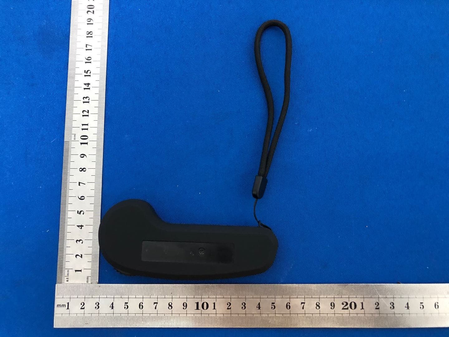
Click to zoom
Application Details
- Equipment Class
- DTS - Digital Transmission System
- Date of Grant
- Aug 10, 2020
- Application Purpose
- Original Equipment
- Date of Application
- Aug 10, 2020
- Equipment Note
- Electric skateboard
- Frequency Range
- 2410.00000000 - 2470.00000000
- Country
- China
Documents & Files
Document Text
Text extracted from the exhibit documents filed with the FCC. Open a document above to read the original.
Users Manual
User Manual of Remote for Skateboard HW6123ENG-20171221 Thank you for purchasing this HOBBYWING product! Any improper operation may cause the unit to function abnormally or even damage relevant devices, so we strongly recommend reading through this user manual before use. Because we have no control over the use, installation, or maintenance of this product, no liability may be assumed for any damage or losses resulting from the use of the product. We do not assume responsibility for any losses caused by unauthorized modifications to our product. Besides, we have the right to modify our product design, appearance, features and usage requirements without notification. We, HOBBYWING, are only responsible for our product cost and nothing else as result of using our product. 01 Specifications 02 Image 03 Functions & Instructions 1) Power On (With the remote powered off), press the “Button A” (on the remote) for 1 second, the remote vibrates a short vibration, enters the connecting mode, and the signal LED starts to flash Red slowly (once a second). (With the board powered off), press the “Power” button on the board (for 0.2 second) to enter the “connecting” mode, and the Red LED on it starts to flash slowly (once a second). Note: the signal LED on the remote and the Red LED on the board turn solid after they are connected to each other. 2) Power Off (Power off) manually: (with the remote & the board powered on), pressing the “Button A” on the remote for 2 seconds can turn off the remote, the remote will vibrate a short vibration after the press; pressing the “Power” button on the board for 1 second can turn off the board. Note: if the remote is still on after the board is turned off, the signal LED on the remote will flash Red slowly and vibrate once to remind the user. Similarly, if the board is still on after the remote is powered off, the Red LED on the board will flash slowly (to warn the user.) (Power off) Automatically: if the user let the board stay still with no further operation for 5 minutes, then the remote and the board will turn off automatically. 3) Connecting & Binding (Remote & Board are bound before leaving the factory) (With the remote & the board powered off,) press the “Power” button on the board for 5 seconds, the Red LED (on it) starts to flash rapidly to indicate that the board enters the binding mode; then press the “Button A” on the remote for 5 seconds, the Signal LED (on it) starts to flash Red rapidly to indicate that the remote enters the binding mode, and the remote vibrates two short vibrations and one long vibration to indicate that the binding succeeds. The signal LED on the remote and the Red LED on the board turn solid when the binding succeeds. Note: when using a new remote and a new board, there is no need to press either the Power button (on the board) or the Button A (on the remote) for 5 seconds to bind them. They enters into the binding mode when they are powered on. 4) Power Indicators Remote Power Indicator (a single LED): after the remote is powered on, if it detects the power is less than 25% (which can barely support an one-hour operation), the Remote Power LED comes on Red; if the power is sufficient (that is the power can support an operation of at least one hour), then the Remote Power LED comes on Green. If there is only 5% of power (which can only support a 15-minute operation) left, the remote will vibrate a double, long vibration (vibrate for 0.5 second, pause for 0.5 second and then vibrate again for 0.5 second ) and the Remote Power LED starts to flash Red slowly (once a second); if there is only 2.5% of power left, the remote will vibrate a double, long vibration again (the same as the previous) and the Remote Power LED starts to flash Red slowly; and if the power is below the regulated value (3.4V) for safe use and the board stops, the remote will vibrate a short vibration and then turn off automatically. Board Power Indicator (4 LEDs in a row): one LED comes on to indicate there is still 25% of power, one LED flashes to indicate there is only 12.5% of power left. For example, if the power ranges from 62.5% to 75%, then the four LEDs will display in this way “○●●●”; if the power ranges from 50%~62.5%, then the four LEDs will display in this way “○☉ ●●”; if the power is below 25%, the remote will vibrate a double, long vibration and the four LEDs will display in this way “○○○●” ; if the power is below 12.5%, the remote will vibrate a double, long vibration and the four LEDs will display in this way “○○○☉”; and if the voltage goes below the regulated value for safe use, then the power output will be cut off. At this time, it’s better to stop using as soon as possible. Notes: the remote will display the power of the remote & the board for 2 seconds and then stop when it’s powered on and connected to the board. Press the Button A at any time can re-trigger the display of the power of the remote & the board. the remote only displays the power of the remote when the board is not connected (to the remote). Attention! “●” means “solid”, “☉” means “flash” and “○” means “die out”. 5) Throttle/Brake Control User can move the “throttle scroll wheel” forward to speed up, and move it backward to brake. Notes: Do not move the “throttle scroll wheel” when pressing the Button A (/Power Switch). If you see the four LEDs (on the remote) flash in the following way: “●○○●”, “○●●○”, “●○○●”, “○●●○”..., then please check if the “throttle scroll wheel” is at the neutral/zero throttle position. 6) Switch of Skateboard Direction When the board is moving forward, if the user moves the Switch C backward, the remote will vibrate a single, short vibration (0.1 second), the four LEDs will flash one by one from front to back to indicate the “Backward mode”. When the board is moving backward, if the user moves the Switch C forward, the remote will vibrate a single, short vibration, the four LEDs will flash one by one from back to front to indicate the “Forward mode”. No…
Text truncated - open the document above for the full version.
Cover Letter(s)
(Shenzhen DBS Technology Co., Ltd.) Federal Communications Commission Authorization and Evaluation Division Confidentiality Request regarding application for certification of FCC ID: 2AWOI3010PP Pursuant to Sections 0.457 and 0.459 of the Commission’s Rules, we hereby request confidential treatment of information accompanying this application as outlined below: Exhibit Type File Name Block Diagram, Schematics, Operational Description Block Diagram Schematics Operational Description The above materials contain trade secrets and proprietary information not customarily released to the public. The public disclosure of these materials may be harmful to the applicant and provide unjustified benefits to its competitors. The applicant understands that pursuant to Section 0.457 of the Rules, disclosure of this application and all accompanying documentation will not be made before the date of the Grant for this application. Sincerely, ( LYU YUAN BO ) Rev 11/20/07
Cover Letter(s)
(Shenzhen DBS Technology Co., Ltd.) Federal Communications Commission Authorization and Evaluation Division 1435 Oakland Mills Road Columbia, MD 21046 Date: 2020.7.31 SUBJECT: FCC Application for FCC ID: 2AWOI3010PP To Whom It May Concern: We, the undersigned, hereby authorize Alan Mei at Shenzhen BCTC Testing Co., Ltd. on our behalf, to apply to the Federal Communications Commission on our equipment. Any and all acts carried out by Alan Mei of Shenzhen BCTC Testing Co., Ltd. on our behalf shall have the same effect as acts of our own. This is to advise that we are in full compliance with the Anti- Drug Abuse Act. We, the applicant, are not subject to a denial of federal benefits pursuant to Section 5301 of the Anti-Drug Act of 1988, 21 USC853a, and no party to the application is subject to a denial of federal benefits pursuant to that section. Regards, (LYU YUAN BO )
External Photos
External Photos
ID Label/Location Info
Label & label location Model:BOARD-3010PP-BLK-STL-1 FCC ID: 2AWOI3010PP
Internal Photos
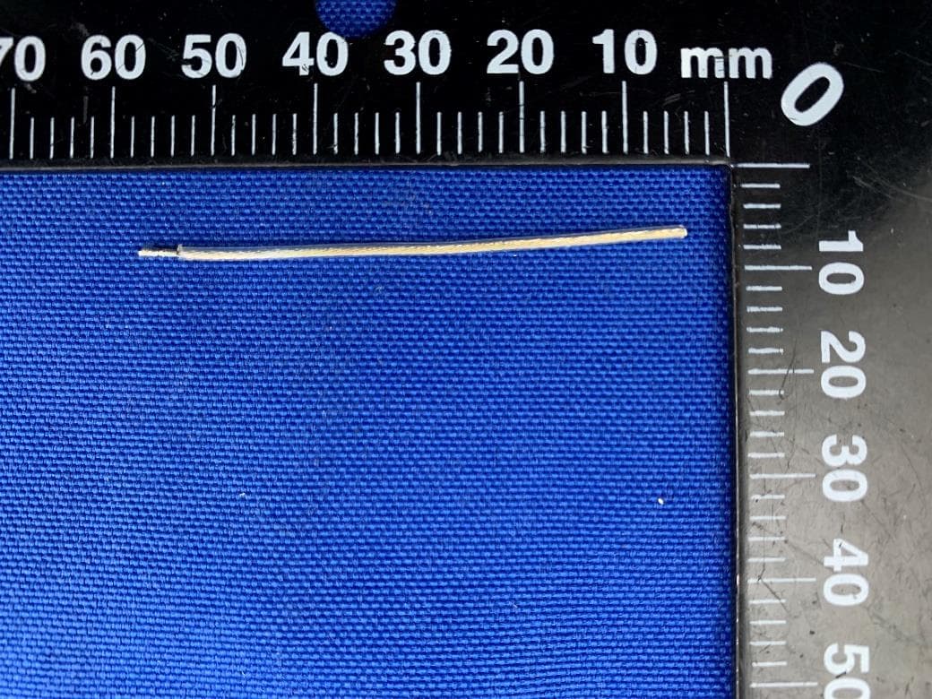
Internal Photos Antenna
RF Exposure Info
RF EXPOSURE EVALUATION METHOD FCC ID: 2AWOI3010PP SAR Test Exclusion Thresholds for 100 MHz – 6 GHz and ≤ 50 mm Approximate SAR Test Exclusion Power Thresholds at Selected Frequencies and Test Separation Distances are illustrated in the following Table. The 1-g and 10-g SAR test exclusion thresholds for 100 MHz to 6 GHz at test separation distances ≤ 50 mm are determined by: [(max. power of channel, including tune-up tolerance, mW)/(min. test separation distance, mm)] · [√f(GHz)] ≤ 3.0 for 1-g SAR and ≤ 7.5 for 10-g extremity SAR,where f(GHz) is the RF channel transmit frequency in GHz Power and distance are rounded to the nearest mW and mm before calculation The result is rounded to one decimal place for comparison The test exclusions are applicable only when the minimum test separation distance is ≤ 50 mm and for transmission frequencies between 100 MHz and 6 GHz. When the minimum test separation distance is < 5 mm, a distance of 5 mm is applied to determine SAR test exclusion. GFSK max possible output power (PK,conducted):8±1dbm 2dBi logarithmic terms convert to numeric result is nearly 1.585 9dbm=7.94mW 2410MHz [(max. power of channel, including tune-up tolerance, mW)/(min. test separation distance,mm)] · [√f(GHz)]=7.94/5*√2.410 =2.46≤3.0 Threshold at which no SAR required is 10mw and ≤ 3.0 for 1-g SAR, Separation distance is 5mm. Modulation Frequency (MHz) Output Power (dBm) Max Antenna Gain (dBi) GFSK 2410 6.78 2 GFSK 2440 7.28 2 GFSK 2470 7.98 2 2440MHz [(max. power of channel, including tune-up tolerance, mW)/(min. test separation distance,mm)] · [√f(GHz)]= 7.94/5*√2.440 =2.48≤3.0 Threshold at which no SAR required is 10mw and ≤ 3.0 for 1-g SAR, Separation distance is 5mm. 2470MHz [(max. power of channel, including tune-up tolerance, mW)/(min. test separation distance,mm)] · [√f(GHz)]=7.94/5*√2.47=2.50≤3.0 Threshold at which no SAR required is 10mw and ≤ 3.0 for 1-g SAR, Separation distance is 5mm. Conclusion: No SAR is required.
Test Report
Shenzhen BCTC Testing Co., Ltd. Report No.: BCTC2007000060E Test Report FCC ID : 2AWOI3010PP Product Name: Electric skateboard Trademark: N/A Model Name : BOARD-3010PP-BLK-STK-1 Prepared For : Shenzhen DBS Technology Co., Ltd. Address : 14th floor, senhainuo Kechuang building, No.1, Dezheng Road, Shilong community, Shiyan street, Bao’an District, Shenzhen, China Prepared By : Shenzhen BCTC Testing Co., Ltd. Address : BCTC Building & 1-2F, East of B Building, Pengzhou Industrial, Fuyuan 1st Road, Qiaotou Community, Fuyong Street, Bao’an District, Shenzhen, China Test Date: Jul. 02, 2020 – Jul. 29, 2020 Date of Report : Jul. 29, 2020 Report No.: BCTC2007000060E Te s t Report Tel: 400-788-9558 Web: https://www.bctc-lab.com BCTC/RF-EMC-007 Ver.:A.0 Page 1 of 41 Shenzhen BCTC Testing Co., Ltd. Report No.: BCTC2007000060E TEST RESULT CERTIFICATION Applicant’s name ................. : Shenzhen DBS Technology Co., Ltd. Address ................................. : 14th floor, senhainuo Kechuang building, No.1, Dezheng Road, Shilong community, Shiyan street, Bao’an District, Shenzhen, China Manufacture's Name ............ : Shenzhen DBS Technology Co., Ltd. Address ................................. : 14th floor, senhainuo Kechuang building, No.1, Dezheng Road, Shilong community, Shiyan street, Bao’an District, Shenzhen, China Product description Product name............................ : Electric skateboard Trademark ................................. : N/A Model and/or type reference : BOARD-3010PP-BLK-STK-1 Standards ............................. : FCC Part15.247 ANSI C63.10:2013 KDB 558074 D01 15.247 Meas Guidance v05r02 This device described above has been tested by BCTC, and the test results show that the equipment under test (EUT) is in compliance with the FCC requirements. And it is applicable only to the tested sample identified in the report. This report shall not be reproduced except in full, without the written approval of BCTC, this document may be altered or revised by BCTC, personal only, and shall be noted in the revision of the document. Prepared by(Engineer): Sam zeng Reviewer(Supervisor): Eric Yang Approved(Manager): Zero Zhou Te s t Report Tel: 400-788-9558 Web: https://www.bctc-lab.com BCTC/RF-EMC-007 Ver.:A.0 Page 2 of 41 Shenzhen BCTC Testing Co., Ltd. Report No.: BCTC2007000060E Table of Contents Page 1 . SUMMARY OF TEST RESULTS 5 1.1 TEST FACILITY 6 1.2 MEASUREMENT UNCERTAINTY 6 2 . GENERAL INFORMATION 7 2.1 GENERAL DESCRIPTION OF EUT 7 2.2 DESCRIPTION OF TEST MODES 8 2.3 BLOCK DIGRAM SHOWING THE CONFIGURATION OF SYSTEM TESTED 8 2.4 DESCRIPTION OF SUPPORT UNITS(CONDUCTED MODE) 9 2.5 EQUIPMENTS LIST FOR ALL TEST ITEMS 10 3 . EMC EMISSION TEST 12 3.1 CONDUCTED EMISSION MEASUREMENT 12 3.1.1 POWER LINE CONDUCTED EMISSION LIMITS 12 3.1.2 TEST PROCEDURE 12 3.1.3 DEVIATION FROM TEST STANDARD 12 3.1.4 TEST SETUP 13 3.1.5 EUT OPERATING CONDITIONS 13 3.1.6 TEST RESULTS 14 3.2 RADIATED EMISSION MEASUREMENT 16 3.2.1 RADIATED EMISSION LIMITS 16 3.2.2 TEST PROCEDURE 17 3.2.3 DEVIATION FROM TEST STANDARD 17 3.2.4 TEST SETUP 18 3.2.5 EUT OPERATING CONDITIONS 19 3.2.6 TEST RESULTS (BETWEEN 9KHZ – 30 MHZ) 20 3.2.7 TEST RESULTS (BETWEEN 30MHZ – 1GHZ) 21 3.3 RADIATED BAND EMISSION MEASUREMENT 24 3.3.1 TEST REQUIREMENT: 24 3.3.2 TEST PROCEDURE 24 3.3.3 DEVIATION FROM TEST STANDARD 25 3.3.4 TEST SETUP 25 3.3.5 EUT OPERATING CONDITIONS 25 4 . POWER SPECTRAL DENSITY TEST 27 4.1 APPLIED PROCEDURES / LIMIT 27 4.1.1 TEST PROCEDURE 27 4.1.2 DEVIATION FROM STANDARD 27 Te s t Report Tel: 400-788-9558 Web: https://www.bctc-lab.com BCTC/RF-EMC-007 Ver.:A.0 Page 3 of 41 Shenzhen BCTC Testing Co., Ltd. Report No.: BCTC2007000060E Table of Contents Page 4.1.3 TEST SETUP 27 4.1.4 EUT OPERATION CONDITIONS 27 4.1.5 TEST RESULTS 28 5 . BANDWIDTH TEST 30 5.1 APPLIED PROCEDURES / LIMIT 30 5.1.1 TEST PROCEDURE 30 5.1.2 DEVIATION FROM STANDARD 30 5.1.3 TEST SETUP 30 5.1.4 EUT OPERATION CONDITIONS 30 5.1.5 TEST RESULTS 31 6 . PEAK OUTPUT POWER TEST 33 6.1 APPLIED PROCEDURES / LIMIT 33 6.1.1 TEST PROCEDURE 33 6.1.2 DEVIATION FROM STANDARD 33 6.1.3 TEST SETUP 33 6.1.4 EUT OPERATION CONDITIONS 33 6.1.5 TEST RESULTS 34 7 . 100 KHZ BANDWIDTH OF FREQUENCY BAND EDGE 35 7.1 APPLICABLE STANDARD 35 7.2 TEST PROCEDURE 35 7.3 DEVIATION FROM STANDARD 35 7.4 TEST SETUP 35 7.5 EUT OPERATION CONDITIONS 35 7.6 TEST RESULTS 35 8 . ANTENNA REQUIREMENT 38 8.1 STANDARD REQUIREMENT 38 8.2 EUT ANTENNA 38 9 . EUT TEST PHOTO 39 10 . EUT PHOTO 41 APPENDIX-PHOTOGRAPHS OF EUT CONSTRUCTIONAL DETAILS Te s t Report Tel: 400-788-9558 Web: https://www.bctc-lab.com BCTC/RF-EMC-007 Ver.:A.0 Page 4 of 41 Shenzhen BCTC Testing Co., Ltd. Report No.: BCTC2007000060E 1. SUMMARY OF TEST RESULTS Test procedures according to the technical standards: FCC Part15 (15.247) , Subpart C Standard Section Test Item Judgment Remark FCC Part15.207 Conducted Emission PASS FCC Part 15.247 (a)(2) 6dB Bandwidth PASS FCC Part 15.247 (b) Peak Output Power PASS FCC Part 15.247 (d) FCC Part 15.209 Radiated Spurious Emission PASS FCC Part 15.247 (e) Power Spectral Density PASS FCC Part 15.205 Restricted Band of Operation PASS FCC Part 15.247(d) Band Edge (Out of Band Emissions) PASS FCC Part15.203 Antenna Requirement PASS NOTE: (1)” N/A” denotes test is not applicable in this Test Report Te s t Report Tel: 400-788-9558 Web: https://www.bctc-lab.com BCTC/RF-EMC-007 Ver.:A.0 Page 5 of 41 Shenzhen BCTC Testing Co., Ltd. Report No.: BCTC2007000060E 1.1 TEST FACILITY Shenzhen BCTC Testing Co., Ltd. Add.: BCTC Building & 1-2F, East of B Building, Pengzhou Industrial, Fuyuan 1st Road, Qiaotou Community, Fuyong Street, Bao’an District, Shenzhen, China FCC Test Firm Registration Number: 712850 IC Registered No.: 23583 1.2 MEASUREMENT UNCERTAINTY The reported uncertainty of measurement y ± U,where expended uncertainty U is based on a standard uncertainty multiplied by a coverage factor of k=2,providing a level of confidence of approximately 95 %。 No. Item Uncertainty 1 3m camber Radiated s…
Text truncated - open the document above for the full version.
Test Setup Photos
Shenzhen BCTC Testing Co., Ltd. Report No.: BCTC2007000060E 1. EUT TEST SETUP PHOTOGRAPHS Spurious emissions Te s t Report Tel: 400-788-9558 Web: https://www.bctc-lab.com BCTC/RF-EMC-0 07 Ver.:A.0 Page 1 of 2 Shenzhen BCTC Testing Co., Ltd. Report No.: BCTC2007000060E Conducted emissions ※※※※※ END OF REPORT ※※※※※ Te s t Report Tel: 400-788-9558 Web: https://www.bctc-lab.com BCTC/RF-EMC-0 07 Ver.:A.0 Page 2 of 2
Contact Information
Applicant
Zhang Mao Mei
Test Firm
Shenzhen BCTC Testing Co., Ltd.Alan Mei
[email protected]+8675536882589
Technical Specifications
| # | Rule Parts | Frequency Range | Power Output |
|---|---|---|---|
| 1 | 15C | 2.41 GHz - 2.47 GHz | 6.28 mW |
Other Applications from Shenzhen DBS Technology Co., Ltd.
2AWOI-RS1
Jan 04, 2023Electric Inline Skate
Equipment Class
DTS - Digital Transmission System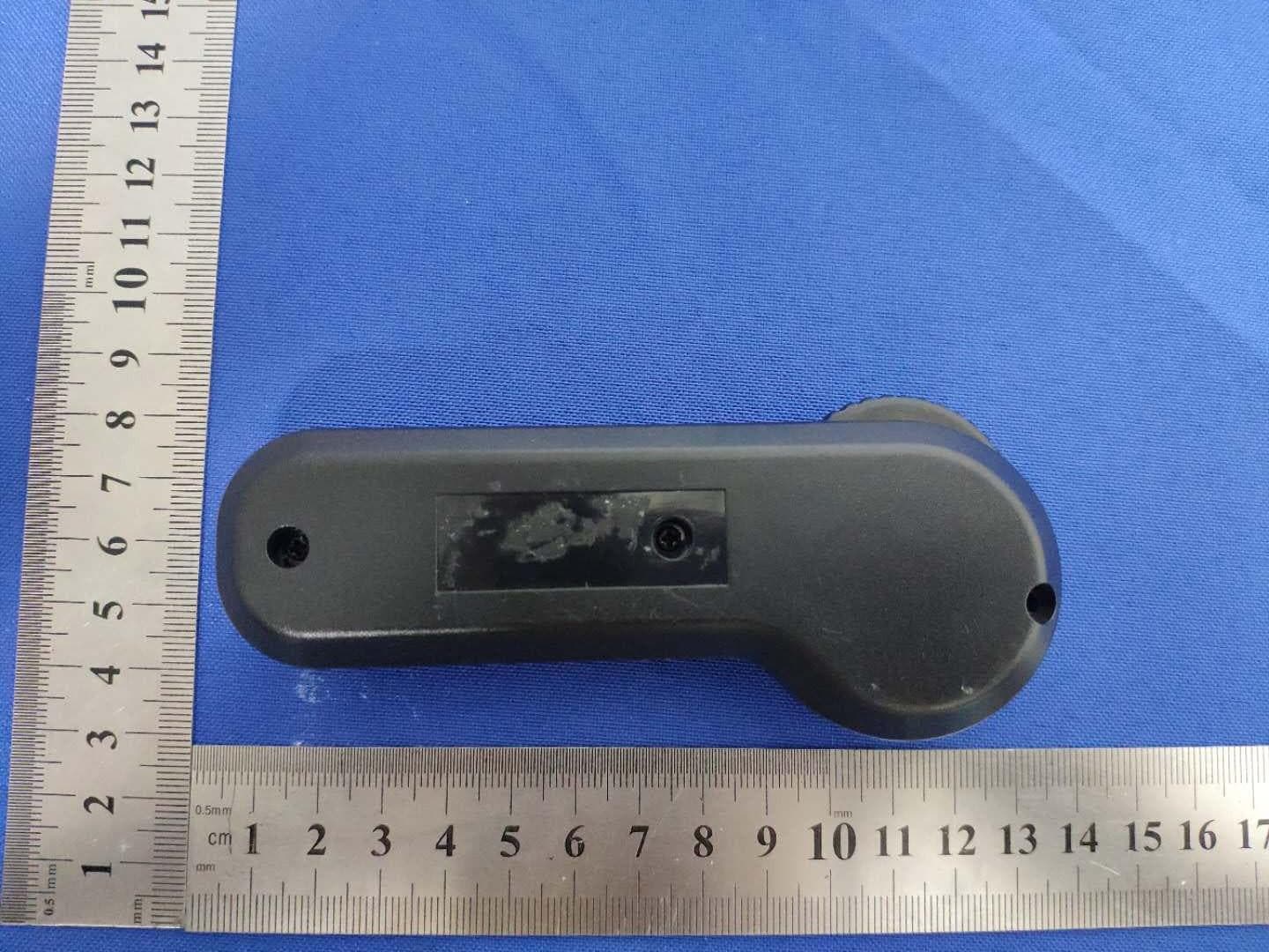
2AWOIJUPITER-02
Jun 21, 2020Electric skateboard
Equipment Class
DTS - Digital Transmission System