2AX6LQTMDMC10Quantum RTLS Dot Compact Mobile Node
ZEROKEY Inc.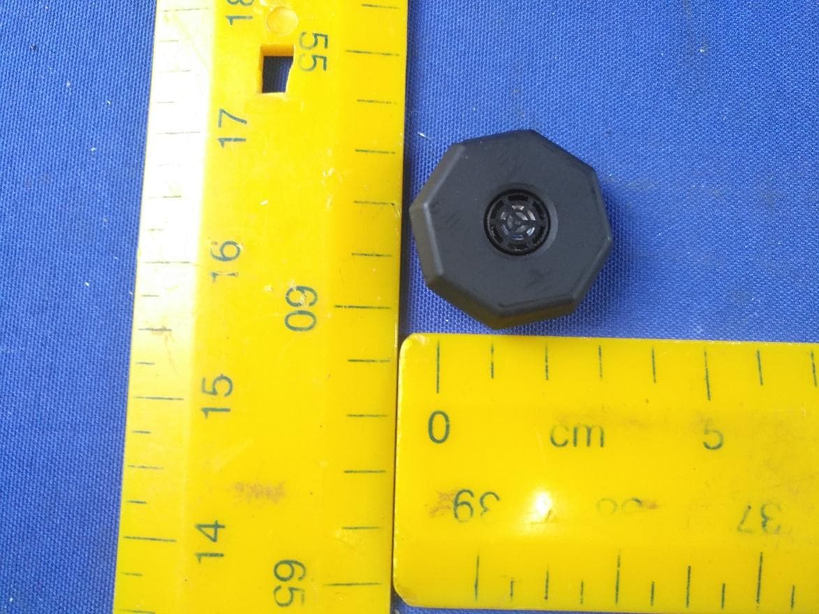
Click to zoom
Application Details
- Equipment Class
- DTS - Digital Transmission System
- Date of Grant
- Jul 12, 2023
- Application Purpose
- Original Equipment
- Date of Application
- Jun 29, 2023
- Equipment Note
- Quantum RTLS Dot Compact Mobile Node
- Frequency Range
- 2402.00000000 - 2480.00000000
- Company
- ZEROKEY Inc.
- Country
- Canada
Documents & Files
Document Text
Text extracted from the exhibit documents filed with the FCC. Open a document above to read the original.
Users Manual
1 2022-11-07 QTM-DMC10 Device Manual QTM-DMC10 Device Manual v1.0.5 Quantum RTLS Dot Compact Mobile Node 2 2022-11-07 QTM-DMC10 Device Manual 05-01-0002 Edition V1 October 2021 Copyright © ZeroKey Inc. All rights reserved. This manual is confidential and proprietary, and may not be reproduced, copied, transmitted, or translated into any language, in any form, or by any means, without the express written permission of ZeroKey Inc. (“ZeroKey”). Product warranty or service will not be extended if: (1) the product is repaired, modified or altered, unless such repair, modification, or alteration is authorized in writing by ZeroKey; or (2) the serial number of the product is defaced or missing. ZEROKEY PROVIDES THIS MANUAL “AS IS” WITHOUT WARRANTY OF ANY KIND, EITHER EXPRESS OR IMPLIED, INCLUDING BUT NOT LIMITED TO THE IMPLIED WARRANTIES OR CONDITIONS OF MERCHANTABILITY OR FITNESS FOR A PARTICULAR PURPOSE. IN NO EVENT SHALL ZEROKEY, ITS DIRECTORS, OFFICERS, EMPLOYEES OR AGENTS BE LIABLE FOR ANY INDIRECT, SPECIAL, INCIDENTAL, OR CONSEQUENTIAL DAMAGES (INCLUDING DAMAGES FOR LOSS OF PROFITS, LOSS OF BUSINESS, LOSS OF USE OR DATA, INTERRUPTION OF BUSINESS AND THE LIKE), EVEN IF ZEROKEY HAS BEEN ADVISED OF THE POSSIBILITY OF SUCH DAMAGES ARISING FROM ANY DEFECT OR ERROR IN THIS MANUAL OR PRODUCT. SPECIFICATIONS AND INFORMATION CONTAINED IN THIS MANUAL ARE FURNISHED FOR INFORMATIONAL USE ONLY, AND ARE SUBJECT TO CHANGE AT ANY TIME WITHOUT NOTICE, AND SHOULD NOT BE CONSTRUED AS A COMMITMENT BY ZEROKEY. ZEROKEY ASSUMES NO RESPONSIBILITY OR LIABILITY FOR ANY ERRORS OR INACCURACIES THAT MAY APPEAR IN THIS MANUAL, INCLUDING THE PRODUCTS AND SOFTWARE DESCRIBED IN IT. Products and corporate names appearing in this manual may or may not be registered trademarks or copyrights of their respective companies and are used only for identification or explanation and to the owners’ benefit, without intent to infringe. Revision Tracking Rev EC Author Reviewer Approver Change Notes Date V1.0.0 N/A C. Lemmon J. Wolf Initial Release 2023/01/06 V1.0.1 N/A J.Wolf -Updated statements for Class B device 2023/04/27 V1.0.2 N/A J. Wolf -Updated wording of FCC and IC statements 2023/05/08 V1.0.3 N/A J. Wolf -Updated certification mark label -Added battery warnings 2023/05/29 V1.0.4 N/A J. Wolf -Updated FCC and ISED wording for portable device 2023/06/06 V1.0.5 N/A J. Wolf -Updated FCC statement as per TUV recommendation 2023/06/21 3 2022-11-07 QTM-DMC10 Device Manual Certification and Compliance The radio used in this device has been certified for use according to Federal Communications Commission (FCC), Industry Canada (IC) and Conformitè Europëenne (CE) rules and regulations. FCC Regulatory Statement Model: QTM-DMC10, FCC ID: 2AX6LQTMDMC10 This device complies with part 15 of the FCC Rules. Operation is subject to the following two conditions: (1) this device may not cause harmful interference, and (2) this device must accept any interference received, including interference that may cause undesired operation. NOTE: This equipment has been tested and found to comply with the limits for a Class B digital device, pursuant to part 15 of the FCC Rules. These limits are designed to provide reasonable protection against harmful interference in a residential installation. This equipment generates, uses, and can radiate radio frequency energy and, if not installed and used in accordance with the instructions, may cause harmful interference to radio communications. However, there is no guarantee that interference will not occur in a particular installation. If this equipment does cause harmful interference to radio or television reception, which can be determined by turning the equipment off and on, the user is encouraged to try to correct the interference by one or more of the following measures: • Reorient or relocate the receiving antenna. • Increase the separation between the equipment and receiver. • Connect the equipment to an outlet on a circuit different from that to which the receiver is connected. • Consult the dealer or an experienced radio/TV technician for help. Changes or modifications to this product not authorized by Zerokey could void the electromagnetic compatibility (EMC) and wireless compliance and negate your authority to operate the product. This equipment can be installed and operated with a minimum distance 5 millimeters between the radiator and user’s body. This equipment has been evaluated to meet general RF exposure requirements at 5 millimeters distance. Part 18 Model: QTM-DWR10, FCC ID: 2AX6LQTMDMC10 This device complies with part 18 of the FCC Rules. This equipment generates, uses, and can radiate radio frequency energy and, if not installed and used in accordance with the instructions, may cause harmful interference to radio communications. However, there is no guarantee that interference will not occur in a particular installation. 4 2022-11-07 QTM-DMC10 Device Manual If this equipment does cause harmful interference to radio or television reception, which can be determined by turning the equipment off and on, the user is encouraged to try to correct the interference by one or more of the following measures: • Reorient or relocate the receiving antenna. • Increase the separation between the equipment and receiver. • Connect the equipment to an outlet on a circuit different from that to which the receiver is connected. • Consult the dealer or an experienced radio/TV technician for help. Responsible party (contact for FCC matters only): Zerokey Inc. 3120 – 12 St NE Calgary, Alberta T2E 8T3 Canada https://zerokey.com/contact/ 5 2022-11-07 QTM-DMC10 Device Manual ISED Regulatory Statement Model: QTM-DMC10, IC: 26679-QTMDMC10 CAN ICES-003(B)/NMB-003(B) This device contains licence-exempt transmitter(s)/receiver(s) that comply with Innovation, Science and Economic Development Canada’s licence-exempt RSS(s). Operation is subject to the following two conditions: (1) This device may not cause interference. (2) …
Text truncated - open the document above for the full version.
Attestation Statements
Rev 1/26/2023 To: Federal Communications Commission Authorization and Evaluation Division 7435 Oakland Mills Road Columbia, MD 21046 USA Date: 05-03-2023 Ref: Attestation Statements Part 2.911(d)(7) Filing FCC ID: 2AX6LQTMDMC10, 2AX6LQTMDWR10 Zerokey Inc. (“the applicant”) certifies that, as of the date of the filing of the application, Zerokey Inc. is our designated U.S. agent for service of process for the above referenced FCC ID. Zerokey Inc. accepts to maintain an agent for no less than one year after the grantee has terminated all marketing and importation or the conclusion of any Commission-related proceeding involving the equipment. Zerokey Inc. accepts, as of the date of the filing of the application, the obligation of the designated U.S. agent for service of process for the above referenced FCC ID. Designated U.S. Agent Information: FRN: 0033756107 Name: Zerokey Inc. Address: 1209 Orange St., Wilmington, Delaware, 19801 Contact Person: Josh Wolf Tel.: 403-612-2925 Email: [email protected] Sincerely, Zerokey Inc (U.S. agent company name printed name) Josh Wolf (U.S. agent company name signature) Zerokey Inc (Applicant printed name) Dave McNab (Applicant signature)
Attestation Statements
Date: 04-27-2023 To: Federal Communications Commission Authorization and Evaluation Division 7435 Oakland Mills Road Columbia, MD 21046 USA Ref: Attestation Statements Part 2.911(d)(5)(i) and Part 2.911(d)(5)(ii) Filing Re. KDB 986446 D01 FCC ID: 2AX6LQTMDMC10 Dear Sir or Madam, Zerokey Inc. (“the applicant”) certifies that the equipment for which authorization is sought is not “covered” equipment prohibited from receiving an equipment authorization pursuant to section 2.903 of the FCC rules. We also certify that, Zerokey Inc. (“the applicant”) certifies that, as of the date of the filing of the application, the applicant is not identified on the Covered List ( as a specifically named entity or any of its subsidiaries or affiliates) as an entity producing “covered” equipment . If you have any questions, please contact us. Sincerely, Contact name: Dave McNab, VP Company name: Zerokey Inc. Address: 3120 12 th St NE, Calgary Alberta, Canada T2E 8T3 E-mail: [email protected] Tel: 1-403-390-5942
Cover Letter(s)
Apri 27, 2023 TUV SUD BABT UNLIMITED Octagon House, Concorde Way, Segensworth North, Fareham, Hampshire, PO15 5RL United Kingdom Dear Sir or Madam, We, ZEROKEY INC. 3120 12TH ST NE, CALGARY ALBERTA, CANADA T2E 8T3 hereby authorize Eric Li, TUV SUD Hong Kong Limited, Unit 301-309, West Wing, Lakeside 2, 10 Science Park West Avenue, Science Park, New Territories Hong Kong, (86) 755 33323232 to act as our agent in all matters relating to applications for equipment authorization, including the signing of all documents relating to these matters. This authorization expires on April 27, 2024. Sincerely, Company Officer: Dave McNab, VP Telephone Number: 1-403-390-5942 Email: [email protected]
Cover Letter(s)
April 27, 2023 TUV SUD BABT UNLIMITED Octagon House, Concorde Way, Segensworth North, Fareham, Hampshire, PO15 5RL United Kingdom Confidentiality Request FCC ID: 2AX6LQTMDMC10 Pursuant to Sections 0.457(d)(1)(ii) and 0.459 of the Commission’s Rules, Zerokey Inc. hereby requests permanent confidential treatment of information accompanying this application as outlined below: Schematics/Layout Bill of Materials/Parts List Block Diagrams Theory of Operation Zerokey Inc. also hereby requests short-term confidential treatment of information accompanying this application as outlined below for a period of 180 days: Internal Photos External Photos User Manual Test Set-up Photographs The above materials contain trade secrets and proprietary information not customarily released to the public. The public disclosure of these matters might be harmful to the Applicant and provide unjustified benefits to its competitors. The Applicant understands that pursuant to Rule 0.457(d)(1)(ii), disclosure of this Application and all accompanying materials will not be made before the date of the Grant for this Application. Yours sincerely, Company Officer: Dave McNab, VP Telephone Number: 1-403-390-5942 Email: [email protected]
Cover Letter(s)
Date: 2023-06-06 To: Federal Communications Commission 7435 Oakland Mills Road Columbia MD FCC ID: 2AX6LQTMDMC10 To Whom It May Concern: This letter is to ascertain that Zerokey Inc. Product name: Quantum RTLS Dot Compact Mobile Node, Model: QTM-DMC10 has been the units used for conducting FCC compliance testing, the SDoC part will be tested by FCC recognized test lab. If you have any question or concerns, please contact us. Sincerely, Contact name: Josh Wolf Company name: Zerokey Inc. Address: 3120 12 St NE Calgary, Alberta, Canada, T2E 8T3 E-mail: [email protected] Tel: 1-403-612-2925
External Photos
Appendix Model: QTM-DMC10 Appendix Model: QTM-DMC10
ID Label/Location Info
QTM-DMC10 PRODUCT LABELING Quantum RTLS Dot Compact Mobile Node product ID label Packaging FCC label Actual Size 3.5” x 2.0” Actual label has rounded corners. MODEL: QTM-DMC10 ZEROKEY Model: QTM-DMC10 FCC Declaration: This device complies with Part 15 of the FCC Rules. Operation is subject to the following two conditions: (1) this device may not cause harmful interference, and (2) this device must accept any interference received, including interference that may cause undesired operation. WARNING: Do not immerse, protect from fluids and dust. FCC ID: 2AX6LQTMDMC10 IC: 26679-QTMDMC10 MSIP R-R-ZKY-QTMDMC10 FCC ID: 2AX6LQTMDMC10 IC: 26679-QTMDMC10 XXX-XXXXX XXX-XXXXX R-R-ZKY-QTMDMC10 Due to the size constraints of the QTM-DMC10, it is not practical to place the label or marking on the product. Thus, the label shall be placed in the user manual. The ‘virtual label’ will be displayed in the user manual as shown below: The Model Number and Serial Number (MAC Address) will be laser etched into the bottom enclosure as shown below: COUNTRY MARK MIN SIZE ID REQUIREMENTS MIN SIZE REQ’D US 5 mm 2AX6LQTMDMC10 4 PT YES CANADA N/A N/A 26679-QTMDMC10 5 PT YES AUS/NZ 5 mm N/A 5 PT YES EUROPE 5 mm N/A 5 PT YES KOREA 5 mm R-R-ZKY-QTMDMC10 5 PT YES JAPAN 5 mm XXX-XXXXXX Located beside mark (Number assigned by VCCI) 5 PT YES
Internal Photos
Appendix Model: QTM-DMC10 Appendix Model: QTM-DMC10 Appendix Model: QTM-DMC10
RF Exposure Info
Report Number: 60.790.23.001.01R01 TÜV SÜD Certification and Testing (China) Co., Ltd. Shenzhen Branch Building 12&13, Zhiheng Wisdomland Business Park, Nantou Checkpoint Road 2, Nanshan District, 518052 Shenzhen, CHINA Page 51 of 51 Radiofrequency radiation exposure evaluation This exposure evaluation is intended forFCC ID: 2AX6LQTMDMC10 According to KDB 447498 D01v06 section 4.3.1, For frequencies between 100 MHz to 6GHz and test separation distances ≤ 50 mm, the Numeric threshold is determined as: Step a) [(max. power of channel, including tune-up tolerance, mW) / (min. test separation distance, mm)] · [√f(GHz)] ≤ 3.0 for 1-g SAR >> The fundamental frequency of the EUT is 2402-2480MHz, the test separation distance is ≤ 50mm. (Manufacturer specified the separation distance is: 20cm) (5mm is the worst case according to the KDB) Step b) >> Numeric threshold (2402MHz), mW / 5mm * √2.402GHz ≤ 3.0 Numeric threshold (2402MHz) ≤ 9.678mW >> Numeric threshold (2440MHz), mW / 5mm * √2.440GHz ≤ 3.0 Numeric threshold (2440MHz) ≤ 9.602mW >> Numeric threshold (2480MHz), mW / 5mm * √2.480GHz ≤ 3.0 Numeric threshold (2480MHz) ≤ 9.525mW >> The power (measured + tune up tolerance) of EUT at 2402MHz is: -1.08dBm = 0.78mW The power (measured + tune up tolerance) of EUT at 2440MHz is: -2.42dBm = 0.57mW The power (measured + tune up tolerance) of EUT at 2480MHz is: -3.43dBm = 0.45mW Which is smaller than the Numeric threshold. Therefore, the device is exempt from stand-alone SAR test requirements. Reviewed by: Prepared by: _________________________________________ Eric LIHosea CHAN Section ManagerEMC Project Engineer 10AppendixA-General Product Information
Test Report
Report Number: 60.790.23.001.01R01 TÜV SÜD Certification and Testing (China) Co., Ltd. Shenzhen Branch Building 12&13, Zhiheng Wisdomland Business Park, Nantou Checkpoint Road 2, Nanshan District, 518052 Shenzhen, CHINA Page 1 of 51 FCC - TEST REPORT Report Number:60.790.23.001.01R01Date of Issue:7 March 2023 Model:QTM-DMC10 Product Type:Quantum RTLS Dot Compact Mobile Node Applicant: ZEROKEY Inc. Address: 3120 12 Street NE, Calgary Alberta, T2E 8T3 Canada Production Facility : ZEROKEY Inc. Address: 3120 12 Street NE,Calgary Alberta, T2E 8T3 Canada Test Result:nPositiveoNegative Total pages including Appendices : 51 TÜV SÜD Certification and Testing (China) Co., Ltd. Shenzhen Branch is a subcontractor to TÜV SÜD Product Service GmbH according to the principles outlined in ISO 17025. TÜV SÜD Certification and Testing (China) Co., Ltd. Shenzhen Branch reports apply only to the specific samples tested under stated test conditions. Construction of the actual test samples has been documented. It is the manufacturer's responsibility to assure that additional production units of this model are manufactured with identical electrical and mechanical components. The manufacturer/importer is responsible to the Competent Authorities in Europe for any modifications made to the production units which result in non-compliance to the relevant regulations. TÜV SÜD Certification and Testing (China) Co., Ltd. Shenzhen Branch shall have no liability for any deductions, inferences or generalizations drawn by the client or others from TÜV SÜD Certification and Testing (China) Co., Ltd. Shenzhen Branch issued reports. This report is the confidential property of the client. As a mutual protection to our clients, the public and ourselves, extracts from the test report shall not be reproduced except in full without our written approval Report Number: 60.790.23.001.01R01 TÜV SÜD Certification and Testing (China) Co., Ltd. Shenzhen Branch Building 12&13, Zhiheng Wisdomland Business Park, Nantou Checkpoint Road 2, Nanshan District, 518052 Shenzhen, CHINA Page 2 of 51 1 Table of Contents 1 Table of Contents ............................................................................................................ 2 2 Description of Equipment Under Test ............................................................................. 3 3 Summary of Test Standards ........................................................................................... 4 4 Details about the Test Laboratory ................................................................................... 5 4.1 Test Equipment Site List ................................................................................................... 6 4.2 Measurement System Uncertainty .................................................................................... 7 5 Summary of Test Results ................................................................................................ 8 6 General Remarks ............................................................................................................ 9 7 Test Setups ................................................................................................................... 10 7.1 Radiated test setups Below 1GHz................................................................................... 10 7.2 Radiated test setups Above 1GHz .................................................................................. 10 7.3 AC Power Line Conducted Emission test setups ............................................................ 11 7.4 Conducted RF test setups............................................................................................... 11 8 Emission Test Results .................................................................................................. 12 8.1 Spurious Radiated Emission ........................................................................................... 12 8.2 6dB & 99% Bandwidth .................................................................................................... 16 8.3 Peak Output Power ......................................................................................................... 22 8.4 Spurious Emissions at Antenna Terminals ...................................................................... 28 8.5 100kHz Bandwidth of band edges................................................................................... 34 8.6 Power Spectral Density ................................................................................................... 36 8.7 Antenna Requirement ..................................................................................................... 42 9 Test setup procedure .................................................................................................... 43 10 Appendix A - General Product Information ................................................................. 51 Report Number: 60.790.23.001.01R01 TÜV SÜD Certification and Testing (China) Co., Ltd. Shenzhen Branch Building 12&13, Zhiheng Wisdomland Business Park, Nantou Checkpoint Road 2, Nanshan District, 518052 Shenzhen, CHINA Page 3 of 51 2 Description of Equipment Under Test Description of the Equipment Under Test Product:Quantum RTLS Dot Compact Mobile Node Model no.:QTM-DMC10 FCC ID:2AX6LQTMDMC10 Rating:3.0VDC(CR2032battery) Frequency:2402 MHz – 2480 MHz (Tx and Rx) Antenna gain:Chip Antenna 5.46 dBi Number of operated channel: 79 (1 MHz Channel Separation) Modulation:GFSK Auxiliary Equipment and Software Used during Test: DESCRIPTION MANUFACTURERMODEL NO.S/N ComputerLenovoX2200A72168 Dummy TerminalZEROKEYTEST NODE--- Auxiliary Software Used during Test: DESCRIPTIONSOFTWARE NAMEVERSIONREMARK RF Test Mode SoftwareTera TermPro 2.3--- Report Number: 60.790.23.001.01R01 TÜV SÜD Certification and Testing (China) Co., Ltd. Shenzhen Branch Building 12&13, Zhiheng Wisdomland Business Park, Nantou Checkpoint Road 2, Nanshan District, 51…
Text truncated - open the document above for the full version.
Test Report
Description: 8010 2.4GHz Chip Antenna PART NUMBER: ANT8010LL04R2400A In the effort to improve our products, we reserve the right to make changes judged to be necessary. CONFIDENTIAL AND PROPRIETARY INFORMATION This document contains confidential and proprietary information of Pulse Electronics, Inc. (Pulse) and is protected by copyright, trade secret and other state and federal laws. Its receipt or possession does not convey any rights to reproduce, disclose its contents, or to manufacture, use or sell anything it may describe. Reproduction, disclosure or use without specific written authorization of Pulse is strictly forbidden. For more information: Pulse Worldwide Headquarters Pulse/Larsen Antennas Europe Headquarters Pulse (Suzhou) Wireless Products Co, Inc. 15255 Innovation Drive #100 Pulse GmbH & Do, KG 99 Huo Ju Road(#29 Bldg,4 th Phase San Diego, CA 92128 Vancouver, WA 98683 Zeppelinstrasse 15 Suzhou New District USA USA Herrenberg, Germany Jiangsu Province, Suzhou 215009 PR China Tel:1-858-674-8100 Tel: 1-360-944-7551 - Tel: 49 7032 7806 0 Tel: 86 512 6807 9998 18110 SE 34 th St Bldg 2 Suite 250 Features: Applications: • Size : 8.0x1.0x1.0 mm • Omni-directional radiation • Tape & reel automatic mounting • Reflow process compatible • RoHS compliant •2.4GHz WiFi device •Bluetooth gadget •Zigbee device •ISM band equipment 1 In the effort to improve our products, we reserve the right to make changes judged to be necessary. CONFIDENTIAL AND PROPRIETARY INFORMATION This document contains confidential and proprietary information of Pulse Electronics, Inc. (Pulse) and is protected by copyright, trade secret and other state and federal laws. Its receipt or possession does not convey any rights to reproduce, disclose its contents, or to manufacture, use or sell anything it may describe. Reproduction, disclosure or use without specific written authorization of Pulse is strictly forbidden. Description: 8010 2.4GHz Chip Antenna PART NUMBER: ANT8010LL04R2400A 2 ELECTRICAL SPECIFICATIONS MECHANICAL DRAWING Working Frequency 2.4 ~ 2.5 GHz Bandwidth 170 MHz(Typ.) Return Loss 10.0 dB Min Polarization Linear Azimuth Beamwidth Omni-directional Peak Gain 5.46 dBi(Typ.) Impedance 50 Ω Operating Temperature - 40~105 °C Maximum Power 1 W Termination Ni / Sn (Environmentally-Friendly Leadless) Resistance to Soldering Heats 260 °C , 10sec. NOTE 1. The specification is defined on Pulse evaluation board Dimension L (mm) 1.00 ± 0.10 W (mm) 8.00 ± 0.10 T (mm) 1.00 ± 0.10 C (mm) 0.90 ± 0.15 Terminal name Function S1 Feeding / Soldering Pad S2 Soldering / Feeding Pad In the effort to improve our products, we reserve the right to make changes judged to be necessary. CONFIDENTIAL AND PROPRIETARY INFORMATION This document contains confidential and proprietary information of Pulse Electronics, Inc. (Pulse) and is protected by copyright, trade secret and other state and federal laws. Its receipt or possession does not convey any rights to reproduce, disclose its contents, or to manufacture, use or sell anything it may describe. Reproduction, disclosure or use without specific written authorization of Pulse is strictly forbidden. Description: 8010 2.4GHz Chip Antenna PART NUMBER: ANT8010LL04R2400A 3 REFERENCE DESIGN OF EVALUATION BOARD Outlook and dimension of evaluation board Footprint In the effort to improve our products, we reserve the right to make changes judged to be necessary. CONFIDENTIAL AND PROPRIETARY INFORMATION This document contains confidential and proprietary information of Pulse Electronics, Inc. (Pulse) and is protected by copyright, trade secret and other state and federal laws. Its receipt or possession does not convey any rights to reproduce, disclose its contents, or to manufacture, use or sell anything it may describe. Reproduction, disclosure or use without specific written authorization of Pulse is strictly forbidden. Description: 8010 2.4GHz Chip Antenna PART NUMBER: ANT8010LL04R2400A 4 ELECTRICAL PERFORMANCES Return loss Evaluation board and XYZ direction Radiation pattern Max gain = 5.46 dBi, at (150,150) MEG (mean effective gain) =-1.46 dBi Directivity (dB) = 6.78 Efficiency = -1.32 dB, 73.73 % Marker data 1. 2.37GHz, -10dB 2. 2.45GHz, -24.9dB 3. 2.54GHz, -10dB In the effort to improve our products, we reserve the right to make changes judged to be necessary. CONFIDENTIAL AND PROPRIETARY INFORMATION This document contains confidential and proprietary information of Pulse Electronics, Inc. (Pulse) and is protected by copyright, trade secret and other state and federal laws. Its receipt or possession does not convey any rights to reproduce, disclose its contents, or to manufacture, use or sell anything it may describe. Reproduction, disclosure or use without specific written authorization of Pulse is strictly forbidden. Description: 8010 2.4GHz Chip Antenna PART NUMBER: ANT8010LL04R2400A 5 REVISION HISTORY Revision Date Description Version 1 Oct. 12, 2020 - New issue Mouser Electronics Authorized Distributor Click to View Pricing, Inventory, Delivery & Lifecycle Information: Pulse: ANT8010LL04R2400A
Test Setup Photos
Appendix Model: QTM-DMC10 Radiated Emission Test below 1GHz Radiated Emission Test above 1GHz
Contact Information
Applicant
DAVE S MCNAB(VP Hardware and Production)
Test Firm
TUV SUD Cert & Testing (China) Co., Ltd.Harry Zhou
[email protected]86 755 3332 3281
Technical Specifications
| # | Rule Parts | Frequency Range | Power Output |
|---|---|---|---|
| 1 | 15C | 2.40 GHz - 2.48 GHz | 800.00 µW |
Other Applications from ZEROKEY Inc.
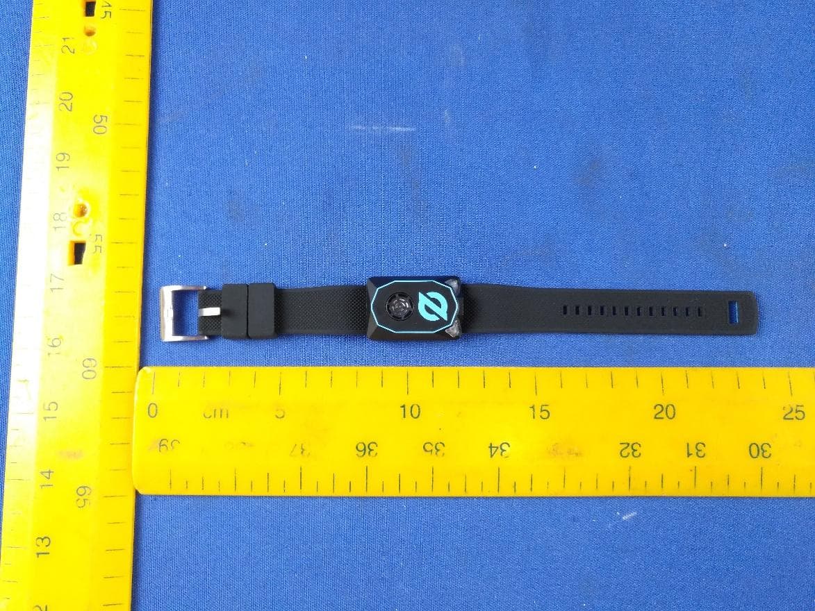
2AX6LQTMDWR10
Jul 20, 2023Quantum RTLS Wristband Mobile Node with ESB
Equipment Class
DTS - Digital Transmission System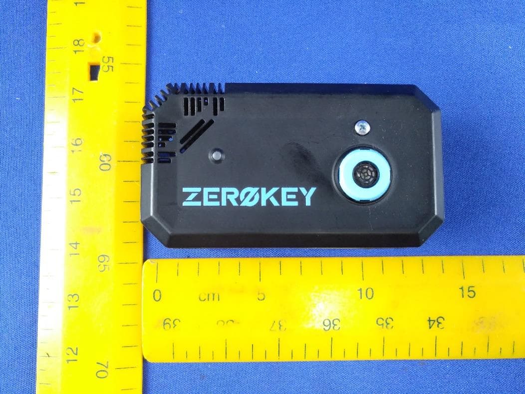
2AX6LQTMEAP11
Dec 11, 2022Quantum RTLS POE Anchor with Nordic Enhanced ShockBurst
Equipment Class
DTS - Digital Transmission System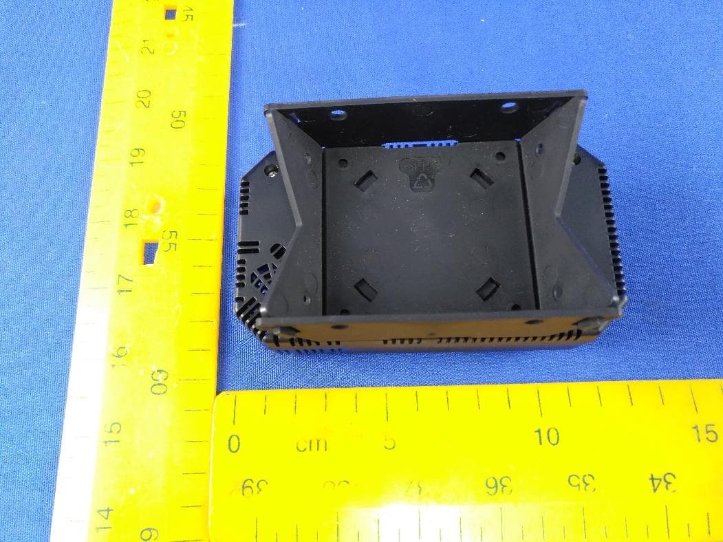
2AX6LQTMEAP10
Dec 11, 2022Quantum RTLS POE Anchor with Nordic Enhanced ShockBurst
Equipment Class
DTS - Digital Transmission System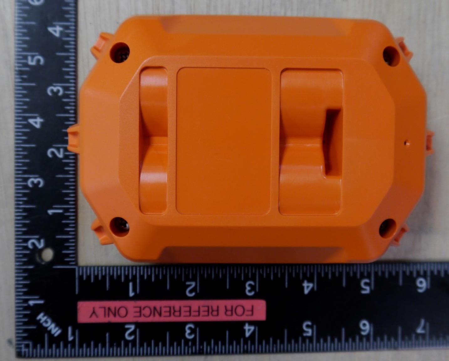
2AX6LISRL10
Jun 29, 2021Relay Node
Equipment Class
DTS - Digital Transmission System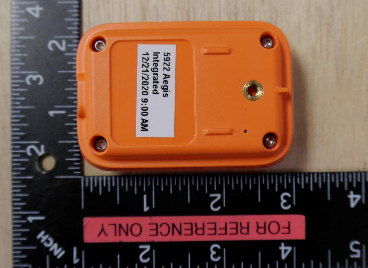
2AX6LISMB10
Jun 29, 2021Mobile Node
Equipment Class
DTS - Digital Transmission System