2AX6X-M1Miu Keeper
SiMPNiC co., Ltd.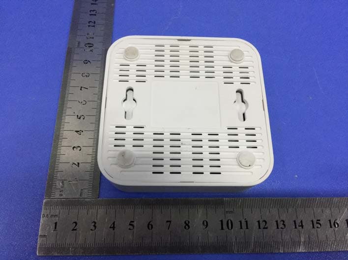
Click to zoom
Application Details
- Equipment Class
- DTS - Digital Transmission System
- Date of Grant
- Jan 10, 2021
- Application Purpose
- Original Equipment
- Date of Application
- Jan 10, 2021
- Equipment Note
- Miu Keeper
- Frequency Range
- 2422.00000000 - 2452.00000000
- Company
- SiMPNiC co., Ltd.
- Country
- Taiwan
Documents & Files
Document Text
Text extracted from the exhibit documents filed with the FCC. Open a document above to read the original.
Users Manual
Quick Installation Guide Miu Keeper Miu キーパースマー 智慧小管家 เอ็มไอยู คีปเปอร์ Model: M1 Contents 1. What’s in package 2. G e t Started 2.1 Preparation 2.2 Connect Miu Keeper to internet 2.2.1 Setup by LAN cable 2.2.2 Setup by wireless 2.3 Add your Miu Keeper to App 2.3.1 By scan QR code 2.3.2 By Wi-Fi search 2.4 Name and login your Miu Keeper 3. FAQ 4. Support 5. FCC Statem ent 6. Warranty 1. What’s in package 1. Miu Keeper 2. USB Type-C cable 3. USB/AC adapter 4. Quick installation guide 5. Warranty 2. Get Started 2.1 Preparation Power on Please turn on the power of Miu Keeper by USB Type-C cable and AC adapter. The LED will light in yellow. Please wait about 2 minutes until turn to red, which means it is ready for Wi-Fi link process. Download SiMPNiC APP Visit App Store (iOS) or Google Play (Android) to download the latest version of SiMPNiC App. User can also scan the QR code below to download too. 2.2 Connect Miu Keeper to internet 2.2.1 Setup by LAN cable Please use Ethernet RJ45 cable to connect Miu Keeper to your Home Wi-Fi router, then connect your smartphone to your home Wi-Fi (2.4GHz), too. 2.2.2 Setup by Wireless Press the back button of Miu Keeper 3 times constantly within 3 seconds, the LED will turn to blink blue for 4 minutes, then please follow the steps below. 1. Please follow the APP amination to connect your smartphone to Wi-Fi that SSID named "SiMPNiC-XXXXXX", the last six letters is from the last six letters of MAC ID that printed on the stick of Miu Keeper, then click next. 2. Select your Home Wi-Fi, key in the password, and click “Send SSID and password” for Miu Keeper to connect. 3. If Miu Keeper is connected to Home Wi-Fi, LED will light in steady blue. 4. There will be a push notice on your screen. 5. Follow APP instruction to go to Wi-Fi settings and make your smartphone re-connect to Home Wi-Fi (2.4GHz). 2.3 Add your Miu Keeper to SiMPNiC App 2.3.1 Scan QR code: Press “Scan QR Code” then use camera of your smartphone (If permission is requested, please press agree) to scan the QR code at the back of Miu Keeper. And then you will find Miu Keeper in your SiMPNiC App. 2.3.2 Wi-Fi-search: Press “Wi-Fi Search” to start search. Miu Keeper will appear in your SiMPNiC App 2.4 Naming and Logging in Your Miu Keeper Naming Key in preferred name for your Miu Keeper. Logging in Key in the default account (admin) and password (admin). After log-in, you have to change password. 3. FAQ Q: If Miu Keeper is successfully setup, how can other family members use it? A: Family members can download SiMPNiC App and open it. If Miu Keeper is already connected to internet, please click "Skip" at welcome page and add Miu Keeper by scanning QR code. Q: My Miu Keeper does not work. What can I do? A: Please re-plug Miu Keeper again to reboot it. You will see the LED light in yellow for two minutes then turn to blue (connected) or red (disconnected). In most cases, Miu Keeper can back to normal after reboot. Q: I try to reboot Miu Keeper, but it still not work. A: In this case, you have to reset Miu Keeper. Notice: once you reset Miu Keeper, all the Wi-Fi linked information saved in Miu Keeper will be lost, you have to re-link Wi-Fi for connection. Q: How to reset Miu Keeper? A: Press the back button of Miu Keeper over 10 seconds. The LED light will turn to yellow. After two minutes, LED will turn to blue (connected) or red (disconnected). 4. Support For more product information, FAQ, and tutorials, please visit SiMPNiC website: YouTube Facebook For More support, please contact us via [email protected] 5. FCC Statement This equipment has been tested and found to comply with the limits for a Class B digital device, pursuant to Part 15 of the FCC Rules. These limits are designed to provide reasonable protection against harmful interference in a residential installation. This equipment generates uses and can radiate radio frequency energy and, if not installed and used in accordance with the instructions, may cause harmful interference to radio communications. However, there is no guarantee that interference will not occur in a particular installation. If this equipment does cause harmful interference to radio or television reception, which can be determined by turning the equipment off and on, the user is encouraged to try to correct the interference by one or more of the following measures: -- Reorient or relocate the receiving antenna. -- Increase the separation between the equipment and receiver. -- Connect the equipment into an outlet on a circuit different from that to which the receiver is connected. -- Consult the dealer or an experienced radio/TV technician for help. This device complies with part 15 of the FCC Rules. Operation is subject to the following two conditions: (1) This device may not cause harmful interference, and (2) this device must accept any interference received, including interference that may cause undesired operation. FCC Radiation Exposure Statement: The equipment complies with FCC Radiation exposure limits set forth for uncontrolled environment. This equipment should be installed and operated with minimum distance 20cm between the radiator and your body. Changes or modifications not expressly approved by the party responsible for compliance could void the user's authority to operate the equipment. 6. Warranty Warranty Disclaimer: Thank you for your interest in the products and services of SiMPNiC. This Limited Warranty applies to physical goods, and only for physical goods, purchased from SiMPNiC. What does this limited warranty cover? This Limited Warranty covers any defects in material or workmanship under normal use during the warranty period. During the warranty period, SiMPNiC will repair or replace, at no charge, products or parts of a product that proves defective because of improper material or workmanship, under normal use and maintenance. What will we do to correct problems? SiMPNiC will either repair the product at no charge, using new or refurbish…
Text truncated - open the document above for the full version.
Cover Letter(s)
CONFIDENTIALITY REQUEST for Certification Service in USA Federal Communication Commission Equipment Authorization Division, Application Processing Branch 7435 Oakland Mills Road Columbia, MD 21046 Date:<2020/12/28> Pursuant to Paragraphs §0.457 and 0.459 of the Commission’s Rules (47 C.F.R.) and Section §552(b)(4) of the Freedom of Information Act, we requests confidentiality for the following products: FCC ID Model name 2AX6X-M1 M1 For the product stated above, we request that the following information be held confidential; Exhibits Long-Term Confidentiality Short-Term Confidentiality Short-Term Confidentiality Days External Photos Internal Photos Block Diagram Schematics Test Setup Photos User’s Manual Parts List Tune Up Operational Descriptions The long-term confidentiality exhibits contain our trade secrets and proprietary information that could be of benefit to our competitors. The short-term confidentiality on the basis of ensuring that business sensitive information remains confidential until the actual marketing of our new device. If you have any questions, please feel free to contact me at the address shown below. Sincerely, Name/Title: Leo Lee/PM Manager Company: Simpnic co., Ltd. Address: 16F-6, No. 79, Sec 1, Xintai 5th Rd, Xizhi Dist.,New Taipei City, Taiwan Phone: 886-2-2698-9661 Fax: 886-2-2698-3960 E-Mail: [email protected]
Cover Letter(s)
Simpnic co., Ltd. 16F-6, No. 79, Sec 1, Xintai 5th Rd, Xizhi Dist.,New Taipei City, Taiwan Date: 2020/12/28 FCC ID: 2AX6X-M1 Model Number: M1 To: Federal Communications Commission Authorization and Evaluation Division 7435 Oakland Mills Road Columbia, MD To Whom It May Concern, We, Simpnic co., Ltd., declare that this EUT (FCC ID: 2AX6X-M1 ) doesn’t have Ad Hoc mode function on “non-US/Canada frequencies”. In addition. The frequency selection feature is disabled by firmware for devices marked to the US/Canada. For DTS part of this device, only channels 1-11 will be used in North America, Country code selection is disabled. Should you have any questions or comments regarding this matter, please have my best attention. Sincerely, Name/Title: Leo Lee/PM Manager Company: Simpnic co., Ltd. Address: 16F-6, No. 79, Sec 1, Xintai 5th Rd, Xizhi Dist.,New Taipei City, Taiwan Phone: 886-2-2698-9661 Fax: 886-2-2698-3960 E-Mail: [email protected]
Cover Letter(s)
Simpnic co., Ltd. 16F-6, No. 79, Sec 1, Xintai 5th Rd, Xizhi Dist.,New Taipei City, Taiwan Federal Communications Commission Authorization and Evaluation Division Equipment Authorization Branch 7435 Oakland Mills Road Columbia, MD 21046 2020/12/28 To whom it may concern: We, Simpnic co., Ltd. the undersigned, hereby authorize Eurofins Product Service GmbH to act on our behalf in all matters relating to applications for equipment authorization FCC ID: 2AX6X-M1 including the signing of all documents related to these matters. Any and all acts carried out by Eurofins Product Service GmbH on our behalf shall have the same effect as acts of our own. We also hereby certify that no party to this application is subject to a denial of benefits, including FCC benefits, pursuant to Section 5301 of the Anti-Drug Abuse Act of 1988, 21 U.S.C. 862. Sincerely, Name/Title: Leo Lee/PM Manager Company: Simpnic co., Ltd. Address: 16F-6, No. 79, Sec 1, Xintai 5th Rd, Xizhi Dist.,New Taipei City, Taiwan Phone: 886-2-2698-9661 Fax: 886-2-2698-3960 E-Mail: [email protected]
External Photos
Page: 3 of 11 FCC ID: 2AX6X-M1 TB-RF-074-1.0 Appendix III EUT External Photographs Photo 1 Appearance of EUT Photo 2 Appearance of EUT Page: 4 of 11 FCC ID: 2AX6X-M1 TB-RF-074-1.0 Photo 3 Appearance of EUT Photo 4 Appearance of EUT Page: 5 of 11 FCC ID: 2AX6X-M1 TB-RF-074-1.0 Photo 5 Appearance of EUT Photo 6 Appearance of EUT Page: 6 of 11 FCC ID: 2AX6X-M1 TB-RF-074-1.0 Photo 7 Appearance of EUT Photo 8 Appearance of Adapter
ID Label/Location Info
Page: 1 of 11 FCC ID: 2AX6X-M1 TB-RF-074-1.0 Appendix IFCC ID Label Size: 37mm X 28mm Page: 2 of 11 FCC ID: 2AX6X-M1 TB-RF-074-1.0 Appendix II ID Label Location ID LOCATION
Internal Photos
Page: 7 of 11 FCC ID: 2AX6X-M1 TB-RF-074-1.0 Appendix IV EUT Internal Photographs Photo 9 Internal of EUT Photo 10 Internal of EUT 2.4GWIFI ANTENNA B 2.4GWIFI ANTENNA A Page: 8 of 11 FCC ID: 2AX6X-M1 TB-RF-074-1.0 Photo 11 Appearance of PCB Photo 12 Appearance of PCB Page: 9 of 11 FCC ID: 2AX6X-M1 TB-RF-074-1.0 Photo 13 Appearance of PCB
RF Exposure Info
Shenzhen Toby Technology Co., Ltd. Report No.: TB-MPE177435 Page: 1 of 4 TB-RF-073-3.0 1A/F., Bldg.6, Yusheng Industrial Zone, The National Road No.107 Xixiang Section 467, Xixiang, Bao’an, Shenzhen, China Tel: +86 75526509301 Fax: +86 75526509195 Maximum Permissible Exposure Evaluation FCC ID: 2AX6X-M1 1. Client Information Applicant : Simpnic co., Ltd. Address : 16F-6, No. 79, Sec 1, Xintai 5th Rd, Xizhi Dist.,New Taipei City, Taiwan Manufacturer : Suzhou WINTECH Electronics Technology Co., Ltd Address : Building 1, No. 2639, tianedang Road, Wuzhong District, Suzhou City, Jiangsu Province, China 2. General Description of EUT EUT Name : Miu Keeper Models No. : M1 Model Difference : N/A Sample ID : 20200928-20-1_02 Brand Name : SiMPNiC Product Description : Operation Frequency: 802.11b/g/n(HT20): 2412MHz~2462MHz 802.11n(HT40): 2422MHz~2452MHz Power Rating : AC/DC Adapter(Model: A18A-050100U-US2): Input: AC 100-240V, 50/60Hz 0.2A Max Output: DC 5V, 1A Software Version : B04 Hardware Version : M1-B04 Connecting I/O Port(S) : Please refer to the User's Manual Report No.: TB-MPE177435 Page: 2 of 4 TB-RF-075-1.0 MPE Calculations 1. Antenna Gain: Antenna Brand Model Name Type 2.4G Antenna Gain(dBi) ANT. A N/A N/A FPC 3.68 ANT. B N/A N/A FPC 3.68 Note: For MIMO mode: Directional Gain=ANT. Gain+10*LOG(N ANT ) =6.69dBi 2.4G working with 802.11g/n(HT20/HT40) has MIMO mode. 2. EUT Operation Condition: Software provided by client enabled the EUT to transmit and receive data at lowest, middle and highest channel individually. 3. Exposure Evaluation: Equation from page 18 of OET Bulletin 65, Edition 97-01 S=(PG)/4πR 2 Where S: power density P: power input to the antenna G: power gain of the antenna in the direction of interest relative to an isotropic radiator. R: distance to the center of radiation of the antenna 4. Simultaneous transmission MPE Considerations According to KDB447498 :All transmitters and antennas in the host must be either evaluated for MPE compliance, by measurement or computational modeling, or qualify for the standalone MPE test exclusion in section 7.1.Simultaneous transmission MPE test exclusion applies when the sum of the MPE ratios for all simultaneous transmitting antennas incorporated in a host device, based on the calculated/estimated, numerically modeled or measured field strengths or power density, is ≤ 1.0. This means that: ∑ of MPE ratios ≤ 1.0 Report No.: TB-MPE177435 Page: 3 of 4 TB-RF-075-1.0 5. Standalone MPE Evaluation: [2.4GHz WLAN] Mode Channel Frequency Peak Conducted Output Power (dBm) Tolerance ± (dB) Turn-up Power Tolerance (dB) Ant. A Ant. B Ant.A Ant.B IEEE 802.11b 1 2412 13.57 13.17 1.0 13±1 13±1 6 2437 12.04 11.71 1.0 13±1 11±1 11 2462 10.91 10.83 1.0 11±1 11±1 IEEE 802.11g 1 2412 21.02 19.73 1.0 21±1 19±1 6 2437 20.78 17.93 1.0 21±1 18±1 11 2462 19.74 19.05 1.0 20±1 20±1 IEEE 802.11n HT20 1 2412 21.80 20.00 1.0 21±1 20±1 6 2437 21.55 18.59 1.0 21±1 18±1 11 2462 21.22 19.26 1.0 21±1 19±1 IEEE 802.11n HT40 3 2422 21.08 19.23 1.0 21±1 19±1 6 2437 21.55 18.40 1.0 21±1 18±1 9 2452 20.59 17.52 1.0 21±1 17±1 2.4GHz WLAN ANT. A Modulation Type Output power (Turn-up Procedure) Antenna Gain (dBi) Antenna Gain (Numeric) Distance (cm) [R] MPE (mW/cm 2 ) MPE Limits (mW/cm 2 ) dBm mW 3.6825.1214.00IEEE 802.11b 2.3335 20 0.0117 1.0000 3.68158.4922.00IEEE 802.11g 2.3335 20 0.0736 1.0000 3.68158.4922.00IEEE 802.11n HT20 2.3335 20 0.0736 1.0000 3.68158.4922.00IEEE 802.11n HT40 2.3335 20 0.0736 1.0000 2.4GHz WLAN ANT. B Modulation Type Output power (Turn-up Procedure) Antenna Gain (dBi) Antenna Gain (Numeric) Distance (cm) [R] MPE (mW/cm 2 ) MPE Limits (mW/cm 2 ) dBm mW 3.6825.1214.00IEEE 802.11b 2.3335 20 0.0117 1.0000 3.68125.8921.00IEEE 802.11g 2.3335 20 0.0584 1.0000 3.68125.8921.00IEEE 802.11n HT20 2.3335 20 0.0584 1.0000 3.68100.0020.00IEEE 802.11n HT40 2.3335 20 0.0464 1.0000 Remark: 1. Output power (Average) including turn-up tolerance; 2. Output power was adjust to duty cycle at 100% if measured duty cycle less than 98%; 3. MPE evaluate distance is 20cm from user manual provide by manufacturer. Report No.: TB-MPE177435 Page: 4 of 4 TB-RF-075-1.0 6. Summary simultaneous transmission information Modulation Type Work Frequency Band Transmit Antenna Antenna A Antenna B Synchronization transmit Antenna A Antenna B IEEE 802.11b 2.4GHz Yes Yes No IEEE 802.11g 2.4GHz Yes Yes Yes IEEE 802.11n HT20 2.4GHz Yes Yes Yes IEEE 802.11n HT40 2.4GHz Yes Yes Yes 7. Summary simultaneous transmission results Antenna A and Antenna B for 2.4GWLAN Modulation Type MPE Antenna A (mW/cm 2 ) MPE Antenna B (mW/cm 2 ) ∑MPE ratios Limit Results IEEE 802.11b 0.01170.0117/ 1.0 PASS IEEE 802.11g 0.07360.05840.1320 1.0 PASS IEEE 802.11n HT20 0.07360.05840.1320 1.0 PASS IEEE 802.11n HT40 0.0736 0.0464 0.1200 1.0 PASS Maximum Simultaneous transmission MPE Ratios is 0.1320≤1.0. 8. Conclusion: The measurement results comply with the FCC Limit per 47 CFR 2.1091 for the uncontrolled RF Exposure of mobile device. -----END OF REPORT-----
Test Report
Shenzhen Toby Technology Co., Ltd. Report No.: TB-FCC177434 Page: 1 of 109 TB-RF-073-3.0 1A/F., Bldg.6, Yusheng Industrial Zone, The National Road No.107 Xixiang Section 467, Xixiang, Bao’an, Shenzhen, China Tel: +86 75526509301 Fax: +86 75526509195 FCC Radio Test Report FCC ID: 2AX6X-M1 Original Grant Report No. : TB-FCC177434 Applicant : Simpnic co., Ltd. Equipment Under Test (EUT) EUT Name : Miu Keeper Model No. : M1 Series Model No. : N/A Sample ID : 20200928-20-1_02 Brand Name : SiMPNiC Receipt Date : 2020-11-24 Test Date : 2020-11-25 to 2020-12-25 Issue Date : 2020-12-26 Standards : FCC Part 15, Subpart C 15.247 Test Method : ANSI C63.10: 2013 Conclusions : PASS In the configuration tested, the EUT complied with the standards specified above, The EUT technically complies with the FCC requirements Test/Witness Engineer : Rebeca Engineer Supervisor : Ivan Su Engineer Manager : Ray Lai This report details the results of the testing carried out on one sample. The results contained in this test report do not relate to other samples of the same product. The manufacturer should ensure that all products in series production are in conformity with the product sample detailed in the report. Report No.: TB-FCC177434 Page: 2 of 109 TB-RF-073-3.0 Contents CONTENTS ............................................................................................................................................. 2 1. GENERAL INFORMATION ABOUT EUT ............................................................................. 5 1.1 Client Information ................................................................................................................. 5 1.2 General Description of EUT (Equipment Under Test) ................................................... 5 1.3 Block Diagram Showing the Configuration of System Tested ...................................... 7 1.4 Description of Support Units .............................................................................................. 7 1.5 Description of Test Mode .................................................................................................... 8 1.6 Description of Test Software Setting ................................................................................ 9 1.7 Measurement Uncertainty ................................................................................................ 10 1.8 Test Facility ......................................................................................................................... 10 2. TEST SUMMARY ..................................................................................................................... 11 3. TEST SOFTWARE ................................................................................................................... 11 4. TEST EQUIPMENT .................................................................................................................. 12 5. CONDUCTED EMISSION TEST ........................................................................................... 13 5.1 Test Standard and Limit .................................................................................................... 13 5.2 Test Setup ........................................................................................................................... 13 5.3 Test Procedure ................................................................................................................... 14 5.4 Deviation From Test Standard ......................................................................................... 14 5.5 EUT Operating Mode ........................................................................................................ 14 5.6 Test Data ............................................................................................................................. 14 6. RADIATED EMISSION TEST ................................................................................................ 15 6.1 Test Standard and Limit .................................................................................................... 15 6.2 Test Setup ........................................................................................................................... 16 6.3 Test Procedure ................................................................................................................... 17 6.4 Deviation From Test Standard ......................................................................................... 18 6.5 EUT Operating Condition ................................................................................................. 18 6.6 Test Data ............................................................................................................................. 18 7. RESTRICTED BANDS REQUIREMENT ............................................................................. 19 7.1 Test Standard and Limit .................................................................................................... 19 7.2 Test Setup ........................................................................................................................... 19 7.3 Test Procedure ................................................................................................................... 20 7.4 Deviation From Test Standard ......................................................................................... 20 7.5 EUT Operating Condition ................................................................................................. 20 7.6 Test Data ............................................................................................................................. 20 8. BANDWIDTH TEST ................................................................................................................. 21 8.1 Test Standard and Limit ..............................................................................................…
Text truncated - open the document above for the full version.
Test Setup Photos
Page: 10 of 11 FCC ID: 2AX6X-M1 TB-RF-074-1.0 Appendix V EUT Test Photographs 15C Test Setup Photo of Setup for Radiated Emission (Above 1 GHz) Photo of Setup for Radiated Emission (Below 1 GHz) Page: 11 of 11 FCC ID: 2AX6X-M1 TB-RF-074-1.0 Photo of Setup for Conducted Emission -----END OF REPORT-----
Contact Information
Applicant
Leo Lee(PM Manager)
Test Firm
Shenzhen Toby Technology Co., Ltd.Ray Lai
Technical Specifications
| # | Rule Parts | Frequency Range | Power Output |
|---|---|---|---|
| 2 | 15C | 2.42 GHz - 2.45 GHz | 212.30 mW |
Other Applications from SiMPNiC co., Ltd.
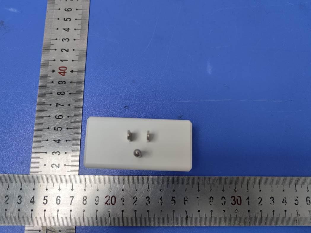
2AX6X-SPG-US-SW
May 19, 2021Smart Plug
Equipment Class
DTS - Digital Transmission System
2AX6X-IRB-01-SW
May 18, 2021Smart IR Blaster
Equipment Class
DTS - Digital Transmission System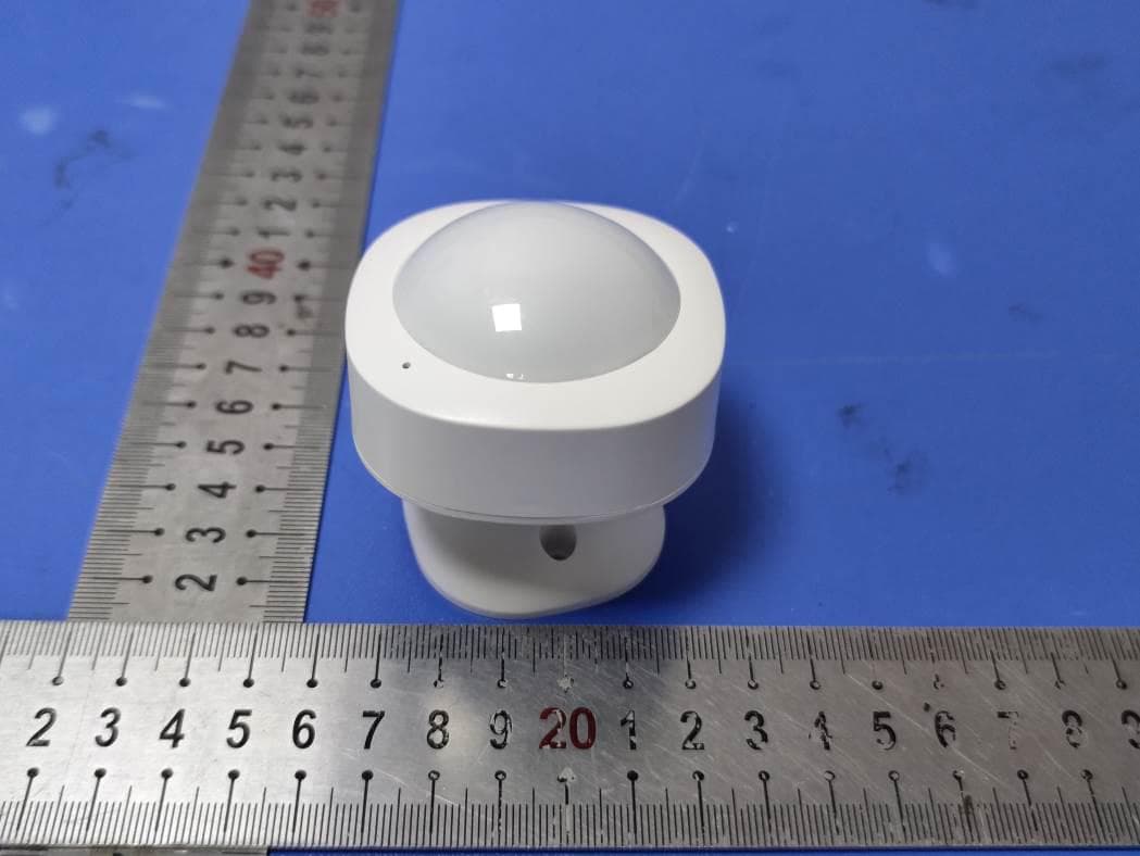
2AX6X-PIR-01-SW
May 18, 2021Smart Motion Sensor
Equipment Class
DTS - Digital Transmission System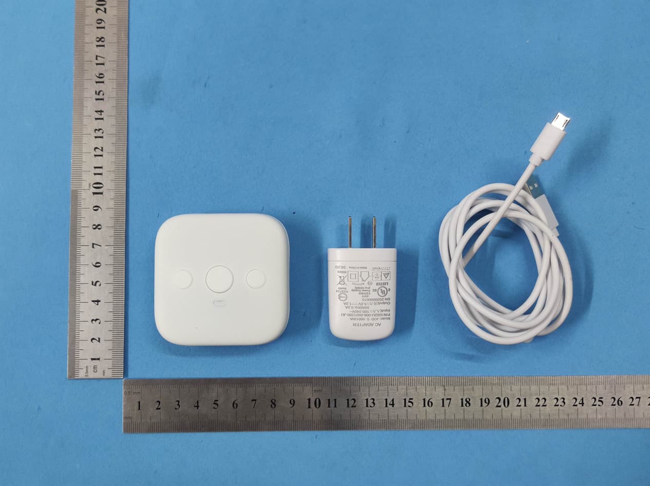
2AX6X-R1
Feb 01, 2021Room Keeper
Equipment Class
DTS - Digital Transmission System