2AXDT-DBIF1Instant Fit ITE (in-the-ear) hearing instrument
WSAUD A/S
Click to zoom
Application Details
- Equipment Class
- DTS - Digital Transmission System
- Date of Grant
- Feb 25, 2021
- Application Purpose
- Original Equipment
- Date of Application
- Feb 25, 2021
- Equipment Note
- Instant Fit ITE (in-the-ear) hearing instrument
- Frequency Range
- 2402.00000000 - 2480.00000000
- Company
- WSAUD A/S
- Country
- Denmark
Documents & Files
Document Text
Text extracted from the exhibit documents filed with the FCC. Open a document above to read the original.
Users Manual
Active, Active Pro, Active Charger User Guide | Master 2 Content Welcome 6 Intended use 7 Your hearing instruments 9 Instrument type 9 Getting to know your hearing instruments 11 Components and names 12 Hearing programs 15 Features 16 Daily use 17 Charging 17 Turning on and off hearing instruments 35 Switching to standby mode 36 3 Inserting and removing the hearing instruments 38 Adjusting the volume 45 Changing the hearing program 46 Special listening situations 47 On the phone 47 Audio streaming with iPhone 49 Airplane mode for hearing instruments 49 Frequently asked questions 51 Maintenance and care 55 Hearing instruments 55 Ear pieces 59 Charger 66 Professional maintenance 67 4 Important safety information for hearing instruments and charger 68 Safety information on lithium-ion rechargeable batteries 68 Safety information for hearing instruments 71 Safety information for charger 71 Further information 79 Accessories 79 Operating, transport and storage conditions 79 Disposal information 84 Symbols 85 Troubleshooting for hearing instruments 90 Troubleshooting for the charger 92 Country-specific information 96 5 Important information 97 Conformance information for charger 97 Service and warranty 106 6 Welcome Thank you for choosing our hearing instruments to accompany you through everyday life. Like anything new, it may take you a little time to become familiar with them. This guide, along with support from your Hearing Care Professional, will help you understand the advantages and greater quality of life your hearing instruments offer. To receive the most benefit from your hearing instruments, it is recommended that you wear them every day, all day. This will help you get adjusted to them. 7 CAUTION It is important to read this user guide and the safety manual thoroughly and completely. Follow the safety information to avoid damage or injury. Before using your hearing instruments for the first time, fully charge them. Intended use Hearing instruments are intended to improve the hearing of hearing impaired persons. Diagnosis and prescription of a hearing instrument must be performed by hearing health specialists, e.g. acousticians, audiologists or ENT doctors. 8 The charger is intended to charge our specific hearing instruments with built-in power cells (lithium-ion rechargeable batteries). Use the hearing instruments and accessories only as described in the respective user guides. 9 Your hearing instruments This user guide describes optional features that your hearing instruments may or may not have. Ask your Hearing Care Professional to indicate the features that are valid for your hearing instruments. Instrument type Your hearing instruments are worn in the outer ear. The instruments are not intended for children under the age of 3 years or persons with a developmental age of under 3 years. 10 A power cell (lithium-ion rechargeable battery) is permanently built into your hearing instrument. This enables easy charging with your charger. The wireless functionality enables advanced audiological features and synchronization between your two hearing instruments. Your hearing instruments feature Bluetooth ® low energy* technology allowing for easy data exchange with your smartphone, and for seamless audio streaming with your iPhone**. * The Bluetooth word mark and logos are owned by the Bluetooth SIG, Inc., and any use of such marks by the legal manufacturer of this product is under licenses. Other trademarks and trade names are those of their respective owners. ** iPad, iPhone, and iPod touch are trademarks of Apple Inc., registered in the U.S. and other countries. 11 Getting to know your hearing instruments Please download the Signia App for remote control features. You can also ask your Hearing Care Professional about another remote control option. 12 Components and names ➊Ear piece ➋Microphone openings ➌Charging contacts ➍ Side indicator (R = right ear, L = left ear) 13 ➊Lid ➋Charging cups ➌LEDs – hearing instruments ➍LED – charger ➎Push button ➏USB power port ➐USB power cable 14 You can use the following standard ear pieces: Standard ear piecesSize Click Sleeve (vented or closed) Click Dome™ single (open or closed) Click Dome semi-open Click Dome double 15 You can easily exchange the standard ear pieces. Read more in section "Maintenance and care". Hearing programs 1 2 3 4 5 6 Read more in section "Changing the hearing program". 16 Features The tinnitus therapy feature generates a sound to distract you from your tinnitus. 17 Daily use Charging Charging your charger – electrical outlet NOTICE Use of incompatible parts poses a risk of malfunction. X Use only the power supply and country specific adapter that is provided with the charger. X Ensure your electrical plug complies with the requirements. Refer to the section "Requirements for the electrical plug". 18 X Connect the USB-C side of the USB power cable to the USB port of the charger ➊ . X Connect the other side of the USB power cable to a suitable electrical plug ➋ . 19 The internal battery starts charging. When hearing instruments are inserted, they start charging as well. The charging status of the charger is shown permanently. Charging your charger – wirelessly X Place the charger on a wireless Qi certified transmitter pad. X After a few seconds the internal battery will start charging indicated by the pulsing green LED of the charger. 20 X When hearing instruments are inserted, they start charging as well indicated by the pulsing green LED of the hearing instruments LED. If the LED is off, please re-align the charger to the center of the Qi transmitter pad. X The charging status of the charger is shown until it is fully charged. After that the LEDs are turned off for power saving reasons. 21 Charging status of your charger The front LED indicates the charging status of the charger and its internal battery. While the internal battery is being charged, the charging status is indicated as follows: LED when charger is charging Pul…
Text truncated - open the document above for the full version.
Users Manual
Safety manual for hearing instruments for US and Canadian markets Master 2 Content Safety information 3 Intended use 3 Explanation of symbols 3 General warnings 5 For certain instrument types 13 For children under the age of 3 years 16 For certain battery types 17 When using remote control apps 18 For Hearing Care Professionals 19 Important information 20 Operating, transport and storage conditions 20 Disposal information 21 Conformance information 21 For US and Canadian markets only 25 For prospective hearing instrument users 25 For hearing instrument users 26 Tinnitus feature 35 For children with hearing loss 38 Warranty and service 39 3 Safety information This safety manual provides safety information and other important information about your hearing instruments. It covers several instrument types and optional features. XRefer to the user guide of your hearing instruments, to check the instrument type and the activated features. Intended use Hearing instruments are intended to improve the hearing of hearing impaired persons. Diagnosis and prescription of a hearing instrument must be performed by hearing health specialists, e.g. acousticians, audiologists or ENT doctors. Use the hearing instruments and accessories only as described in the respective user guides. Explanation of symbols Symbols used in this document Points out a situation that could lead to serious, moderate, or minor injuries. Indicates possible property damage. Information and warnings for children with hearing instruments. 4 Symbols on the device or packaging CE compliance label, confirms compliance with certain European Directives, refer to section "Conformance information". EMC and radio communications compliance label Australia, refer to section "Conformance information". Optional symbol for custom models with wireless functionality. Indicates the legal manufacturer of the device. Do not dispose of the device with general domestic waste. Read more in section "Disposal information". Packaging can be recycled. Read and follow the instructions in the user guide. According to IEC 60601-1, the applied parts of this device are classified as type B. Keep dry during transportation. Temperature during transportation. Read more in section "Operating, transport and storage conditions". 5 Symbols on the device or packaging Relative humidity during transportation. Read more in section "Operating, transport and storage conditions". Atmospheric pressure during transportation. Read more in section "Operating, transport and storage conditions". Medical device Compatible with Qi-certified wireless chargers. Bluetooth ® low energy technology. General warnings WARNING Risk of impairing the residual hearing of the user. XUse only hearing instruments that have been fitted especially for your needs. WARNING Risk of injury! XDo not use obviously damaged devices and return them to point of sale. 6 WARNING Note that any unauthorized changes to the product may cause damage to the product or cause injury. XUse only approved parts and accessories. Ask your Hearing Care Professional for support. WARNING Your hearing instruments may reduce certain background sounds, potentially also traffic or warning signals. WARNING Risk of explosion! XDo not use your hearing instruments in explosive atmospheres (e. g. mining areas). WARNING This product can expose you to nickel, which is known to the State of California to cause cancer. For more information, go to www.P65Warnings.ca.gov. WARNING Choking hazard! Your hearing instruments contain small parts which can be swallowed. XKeep hearing instruments, batteries and accessories out of reach of children and mentally disabled persons. XIf parts have been swallowed consult a physician or hospital immediately. 7 If you have hearing instruments that are intended for the fitting of children under the age of 3 years or persons with a developmental age of under 3 years, refer also to section "For children under the age of 3 years". NOTICE XProtect your hearing instruments from high humidity. Do not wear them in the shower or when you apply make-up, perfume, aftershave, hairspray or suntan lotion. NOTICE XProtect your hearing instruments from extreme heat. Do not store them in direct sunlight. NOTICE XDo not dry your hearing instruments in the microwave oven. NOTICE Different types of strong radiation, e. g. during X-ray or MRI head examinations, may damage hearing instruments. XDo not wear the hearing instruments during these or similar procedures. Weaker radiation, e. g. from radio equipment or airport security, does not damage the hearing instruments. 8 NOTICE Your devices comply with international standards. However, it cannot be guaranteed that all products on the market work interference-free, for example some induction cookers may cause audible interference. NOTICE In case of a serious incident, report the occurrence to the manufacturer of the device. NOTICE When not in use, please store your hearing instruments in the supplied jewel case or charging case (if applicable) and keep out of the reach of children. Contraindications WARNING In case of a known contact allergy, consult the hearing instrument manufacturer regarding the presence of the allergen before using the hearing instrument. If an allergic reaction develops after wearing the hearing instrument, immediately discontinue use and consult a licensed physician. 9 WARNING Consult a Hearing Care Professional if you experience any unusual side effects like skin irritation, excessive accumulation of ear wax, dizziness, change in your hearing, or if you think there may be a foreign object in your ear canal. WARNING A Hearing Care Professional should advise a prospective hearing instrument user to consult a licensed physician before using the hearing instrument if the Hearing Care Professional determines that the prospective user has any of the following conditions: XVisible congenital or traumatic deformity of the ear. XHistory of active drainage from the…
Text truncated - open the document above for the full version.
External Photos
Annex A 1-1606/20-01-01_AnnexA External photos of the Equipment Under Test This addendum is electronically signed and valid without handwritten signature. For verification of the electronic signatures, the public keys can be requested at the testing laboratory. Document authorized: Hans-Joachim Wolsdorfer Lab Manager Radio Communications & EMC CTC advanced GmbHUntertuerkheimer Str. 6-10 66117 Saarbruecken / Germany Phone: +49 681 5 98 - 0 Fax: +49 681 5 98 - 9075 web: ctcadvanced.com e-mail: [email protected] Photos Photo 1 Photo 2 2021-01-06Document No. 1-1606/20-01-01_AnnexA2/4 Photo 3 Photo 4 2021-01-06Document No. 1-1606/20-01-01_AnnexA3/4 Document history VersionApplied changesDate of release initial release2021-01-06 - END OF DOCUMENT - 2021-01-06Document No. 1-1606/20-01-01_AnnexA4/4
Internal Photos
Annex B 1-1606/20-01-01_AnnexB Internal photos of the Equipment Under Test This addendum is electronically signed and valid without handwritten signature. For verification of the electronic signatures, the public keys can be requested at the testing laboratory. Document authorized: Hans-Joachim Wolsdorfer Lab Manager Radio Communications & EMC CTC advanced GmbHUntertuerkheimer Str. 6-10 66117 Saarbruecken / Germany Phone: +49 681 5 98 - 0 Fax: +49 681 5 98 - 9075 web: ctcadvanced.com e-mail: [email protected] Photos Photo 1 Photo 2 2021-02-01Document No. 1-1606/20-01-01_AnnexB2/5 Photo 3 Photo 4 2021-02-01Document No. 1-1606/20-01-01_AnnexB3/5 Photo 5 Photo 6 2021-02-01Document No. 1-1606/20-01-01_AnnexB4/5 Document history VersionApplied changesDate of release initial release2021-02-01 - END OF DOCUMENT - 2021-02-01Document No. 1-1606/20-01-01_AnnexB5/5
Test Report
TEST REPORT Test report no.: 1-1606/20-01-05-A Testing laboratory Applicant CTC advanced GmbH Untertuerkheimer Strasse 6 – 10 66117 Saarbruecken / Germany Phone: + 49 681 5 98 - 0 Fax: + 49 681 5 98 - 9075 Internet: https://www.ctcadvanced.com e-mail: [email protected] Accredited Testing Laboratory: The testing laboratory (area of testing) is accredited according to DIN EN ISO/IEC 17025 (2018-03) by the Deutsche Akkreditierungsstelle GmbH (DAkkS) The accreditation is valid for the scope of testing procedures as stated in the accreditation certificate starting with the registration number: D-PL-12076-01. WSAUD A/S Nymøllevej 6 DK-3540 Lynge / DENMARK Phone: +45 4435 5600 Contact: Richard Rose e-mail: [email protected] Manufacturer WSAUD A/S Nymøllevej 6 DK-3540 Lynge / DENMARK Test standard/s FCC - Title 47 CFR Part 15 FCC - Title 47 of the Code of Federal Regulations; Chapter I; Part 15 - Radio frequency devices RSS - 247 Issue 2 Digital Transmission Systems (DTSs), Frequency Hopping Systems (FHSs) and Licence - Exempt Local Area Network (LE-LAN) Devices For further applied test standards please refer to section 3 of this test report. Test Item Kind of test item: Instant Fit ITE (in-the-ear) hearing instrument Model name: Active; Active Pro; Active Pro DEMO FCC ID: 2AXDT-DBIF1 IC: 26428-DBIF1 Frequency: DTS band 2400 MHz to 2483.5 MHz Technology tested: Bluetooth ® LE Antenna: Integrated antenna Power supply: 3.85 V DC by battery Temperature range: 0°C to +50°C This test report is electronically signed and valid without handwritten signature. For verification of the electronic signatures, the public keys can be requested at the testing laboratory. Test report authorized: Test performed: Marco Bertolino Michael Dorongovski Lab Manager Lab Manager Radio Communications Radio Communications Test report no.: 1-1606/20-01-05-A © CTC advanced GmbH Page 2 of 43 1 Table of contents 1 Table of contents ............................................................................................................................................. 2 2 General information ......................................................................................................................................... 3 2.1 Notes and disclaimer ............................................................................................................................ 3 2.2 Application details ................................................................................................................................ 3 2.3 Test laboratories sub-contracted ......................................................................................................... 3 3 Test standard/s, references and accreditations .............................................................................................. 4 4 Reporting statements of conformity – decision rule ...................................................................................... 5 5 Test environment ............................................................................................................................................. 6 6 Test item .......................................................................................................................................................... 6 6.1 General description ............................................................................................................................... 6 6.2 Additional information .......................................................................................................................... 6 7 Sequence of testing ......................................................................................................................................... 7 7.1 Sequence of testing radiated spurious 9 kHz to 30 MHz ..................................................................... 7 7.2 Sequence of testing radiated spurious 30 MHz to 1 GHz .................................................................... 8 7.3 Sequence of testing radiated spurious 1 GHz to 18 GHz ..................................................................... 9 7.4 Sequence of testing radiated spurious above 18 GHz ....................................................................... 10 8 Description of the test setup.......................................................................................................................... 11 8.1 Shielded semi anechoic chamber ....................................................................................................... 12 8.2 Shielded fully anechoic chamber ........................................................................................................ 13 8.3 Radiated measurements > 18 GHz ...................................................................................................... 14 8.4 Conducted measurements Bluetooth system .................................................................................... 15 9 Measurement uncertainty .............................................................................................................................. 16 10 Summary of measurement results ......................................................................................................... 17 11 Additional comments .............................................................................................................................. 18 12 Measurement results .............................................................................................................................. 19 12.1 System gain ..................................................................................................................................... 19 12.2 Power spectral density .................................................................................................................... 20 12.3 DTS bandwidth – 6 dB bandwidth ............................................…
Text truncated - open the document above for the full version.
Test Report
Measurement Results 1-1606/20-01-05_log1_conducted Test logging This addendum is electronically signed and valid without handwritten signature. For verification of the electronic signatures, the public keys can be requested at the testing laboratory. Document authorized: Michael Dorongovski Lab Manager Radio Communications CTC advanced GmbHUntertuerkheimer Strasse 6-10 66117 Saarbruecken / Germany Phone: +49 681 5 98 - 0 Fax: +49 681 5 98 - 9075 web: ctcadvanced.com e-mail: [email protected] Table of Content EUT Summary3 1. Common2G4 Peak OP 3MHz/3MHz ~ BT LE 1 Msps4 2. FCC Part 15.247 Maximum Peak Conducted Output Power DTS ~ BT LE 1 Msps8 3. FCC Part 15.247 Bandwidth 6dB DTS ~ BT LE 1 Msps15 4. FCC Part 15.247 Peak Power Spectral Density DTS ~ BT LE 1 Msps19 5. FCC Part 15.247 Bandwidth 99PCT-20dB ~ BT LE 1 Msps23 6. FCC Part 15.247 TX Spurious Conduced ~ BT LE 1 Msps30 7. FCC Part 15.247 Restricted Band Edge Conducted Peak DTS Video Avg (cond) ~ BT LE 1 Msps34 Document No. 1-1606/20-01-05_log1_conducted2/36 EUT Summary IUT DEFINITION & Common settings ManufacturerWSAUD A/S TypeActive; Active Pro; Active Pro DEMO Serial No. | Setup No.NI | 1.0 SW Version | HW VersionNI | NI Comment 1 | 2 | Tlow | Tmid | Thigh [°C] 0 | 20 | 50 Vlow | Vmid | Vhigh [V] @Imax [A] 3.85 | 3.85 | 3.85 @1 Auto Control enabled Power Supply | Climatic BoxNo | No Additional Path Loss [dB]0.7 IUT Common Settings BT Low Energy Intermodulation Value N3 Image Freq. Low | Mid | High [MHz]0 | 0 | 0 Power Class2 1 Mbps supportedTrue | TXpayload 255 | RXpayload 37 2 Mbps supportedFalse | TXpayload 255 | RXpayload 255 Longrange S8 supportedFalse | TXpayload 255 | RXpayload 255 Longrange S2 supportedFalse | TXpayload 255 | RXpayload 255 Signaling Settings USB_RS232 | TWO | 13 | 2400 | None | S1 | None | Off Signaling RF Settings RF1com | 0 | 0 | On | User InteractionNo Switch Matrix & Pathcompensation enabledYes Document No. 1-1606/20-01-05_log1_conducted3/36 1. Common2G4 Peak OP 3MHz/3MHz ~ BT LE 1 Msps Test References TC Start21.12.2020 15:41:06 Ambit Temp [°C] | Humidity [rel%] 23.4 | 35 System Version1.0.1.2 Test SpecificationNone Test Method Class / TC VersionTC_VM_Common2G4_Peak_Output_Power_Conducted_3MHz_3MHz_V01 Version: 0.0.1 My DescriptionPeak Output Power conducted 3MHz/3MHz - BT LE 1 Msps Add. Information Test Parameter Technology to testBT LE 1 Msps Antenna Port used1 Temperaturemid Voltagemid Frequency low to testTrue | Freq [MHz] 2402 Frequency mid to testTrue | Freq [MHz] 2440 Frequency high to testTrue | Freq [MHz] 2480 Switched PathIUT - SignalingUnit - SpectrumAnalyzer Devices in useSigBT: Rohde&Schwarz,CMW,1201.0002k75/100683,3.7.170 | SA: Rohde&Schwarz,FSV-30,1321.3008K30/103809,3.70 Document No. 1-1606/20-01-05_log1_conducted4/36 Test at TX 2402 MHz DTM Connection check Test DescriptionLower LimitUpper LimitMeasuredUnitVerdict Connection result------------PASS READ SA SETTINGS: RefLevel [dBm] | RefLevelOffset [dB] | InpAtt [dB]8.28 | 10.79 | 15 Start [MHz] | Stop [MHz]2399.500 | 2404.500 RBW [MHz] | VBW [MHz]3.000000 | 3.000000 Detector | TraceModePOS | MAXH Sweep: Time [ms] | Count | Points per Section | Type1000 | 10 | 1001 | SWE RESULT Test DescriptionLower LimitUpper LimitMeasuredUnitVerdict Peak Power-------1.83dBmInfo Peak Power------0.656145mWInfo Frequency at Peak------2402.255MHzInfo Plot_Common2G4 Peak OP 3MHz-3MHz ~ BT LE 1 Msps_21122020_154134.png Document No. 1-1606/20-01-05_log1_conducted5/36 Test at TX 2440 MHz DTM Connection check Test DescriptionLower LimitUpper LimitMeasuredUnitVerdict Connection result------------PASS READ SA SETTINGS: RefLevel [dBm] | RefLevelOffset [dB] | InpAtt [dB]8.59 | 10.8 | 15 Start [MHz] | Stop [MHz]2437.500 | 2442.500 RBW [MHz] | VBW [MHz]3.000000 | 3.000000 Detector | TraceModePOS | MAXH Sweep: Time [ms] | Count | Points per Section | Type1000 | 10 | 1001 | SWE RESULT Test DescriptionLower LimitUpper LimitMeasuredUnitVerdict Peak Power-------1.5dBmInfo Peak Power------0.707946mWInfo Frequency at Peak------2439.79MHzInfo Plot_Common2G4 Peak OP 3MHz-3MHz ~ BT LE 1 Msps_21122020_154205.png Document No. 1-1606/20-01-05_log1_conducted6/36 Test at TX 2480 MHz DTM Connection check Test DescriptionLower LimitUpper LimitMeasuredUnitVerdict Connection result------------PASS READ SA SETTINGS: RefLevel [dBm] | RefLevelOffset [dB] | InpAtt [dB]8.77 | 10.85 | 15 Start [MHz] | Stop [MHz]2477.500 | 2482.500 RBW [MHz] | VBW [MHz]3.000000 | 3.000000 Detector | TraceModePOS | MAXH Sweep: Time [ms] | Count | Points per Section | Type1000 | 10 | 1001 | SWE RESULT Test DescriptionLower LimitUpper LimitMeasuredUnitVerdict Peak Power-------1.31dBmInfo Peak Power------0.739605mWInfo Frequency at Peak------2479.7MHzInfo Plot_Common2G4 Peak OP 3MHz-3MHz ~ BT LE 1 Msps_21122020_154235.png TEST FINISHED General Verdict21.12.2020 15:42:36 / RT: 89 sPASS Document No. 1-1606/20-01-05_log1_conducted7/36 2. FCC Part 15.247 Maximum Peak Conducted Output Power DTS ~ BT LE 1 Msps Test References TC Start21.12.2020 15:42:40 Ambit Temp [°C] | Humidity [rel%] 23.4 | 35 System Version1.0.1.2 Test SpecificationFCC Part 15.247 Test MethodDTS: KDB 558074 D01 V05 - Chapter 8.3.1.1 RBW ≥ DTS Bandwidth Class / TC VersionTC_VM_FCC15247_Maximum_Peak_Conducted_Output_Power_DTS_V01 Version: 0.0.1 My DescriptionFCC 15.247 Maximum Peak Output Power Conducted DTS - BT LE 1 Msps Add. Information Test Parameter Technology to testBT LE 1 Msps Antenna Port used1 Temperaturemid Voltagemid Frequency low to testTrue | Freq [MHz] 2402 Frequency mid to testTrue | Freq [MHz] 2440 Frequency high to testTrue | Freq [MHz] 2480 Switched PathIUT - SignalingUnit - SpectrumAnalyzer Devices in useSigBT: Rohde&Schwarz,CMW,1201.0002k75/100683,3.7.170 | SA: Rohde&Schwarz,FSV-30,1321.3008K30/103809,3.70 Document No. 1-1606/20-01-05_log1_conducted8/36 Test at TX 2402 MHz DTM Connection check Test DescriptionLower LimitUpper LimitMeasuredUnitVerdict Connection result------------PASS READ SA SETTINGS: RefLevel [dBm] | RefLevelOf…
Text truncated - open the document above for the full version.
Test Setup Photos
Annex D 1-1606/20-01-01_AnnexD Setup photos of the Equipment Under Test This addendum is electronically signed and valid without handwritten signature. For verification of the electronic signatures, the public keys can be requested at the testing laboratory. Document authorized: Michael Dorongovski Lab Manager Radio Communications CTC advanced GmbHUntertuerkheimer Str. 6-10 66117 Saarbruecken / Germany Phone: +49 681 5 98 - 0 Fax: +49 681 5 98 - 9075 web: ctcadvanced.com e-mail: [email protected] Photos Photo 1 Photo 2 2021-01-06Document No. 1-1606/20-01-01_AnnexD2/6 Photo 3 Photo 4 2021-01-06Document No. 1-1606/20-01-01_AnnexD3/6 Photo 5 Photo 6 2021-01-06Document No. 1-1606/20-01-01_AnnexD4/6 Photo 7 2021-01-06Document No. 1-1606/20-01-01_AnnexD5/6 Document history VersionApplied changesDate of release initial release2021-01-06 - END OF DOCUMENT - 2021-01-06Document No. 1-1606/20-01-01_AnnexD6/6
Contact Information
Applicant
Richard Rose
Test Firm
cetecom advanced GmbHGerald Schmidt
Technical Specifications
| # | Rule Parts | Frequency Range | Power Output |
|---|---|---|---|
| 1 | 15C | 2.40 GHz - 2.48 GHz | 740.00 µW |
Other Applications from WSAUD A/S
2AXDT-RFM030
Aug 18, 2026RF Module for Hearing Aids
Equipment Class
DXX - Part 15 Low Power Communication Device Transmitter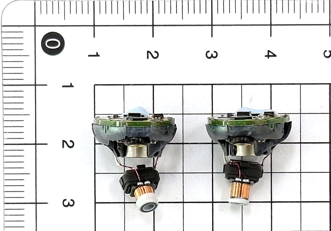
2AXDT-RFM022
Jul 15, 2026RF Module for Hearing Aids
Equipment Class
DXX - Part 15 Low Power Communication Device Transmitter2AXDT-RFM016
Sep 08, 2025RF Module for Hearing Aids
Equipment Class
DTS - Digital Transmission System2AXDT-RFM015
Oct 03, 2024RF Module for Hearing Aids
Equipment Class
DXX - Part 15 Low Power Communication Device Transmitter
2AXDT-TV2
Sep 30, 2024TV streaming adapter
Equipment Class
DTS - Digital Transmission System