2AXDT-RFM005RF Module 5 for Hearing Instruments
WSAUD A/S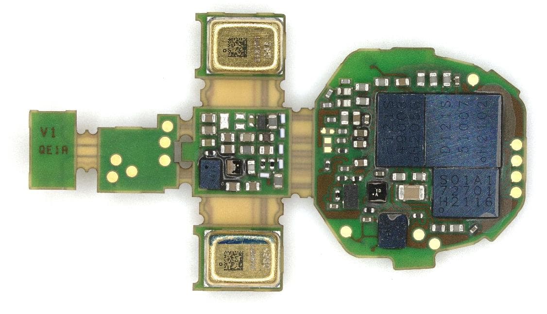
Click to zoom
Application Details
- Equipment Class
- DXT - Part 15 Low Power Transceiver, Rx Verified
- Date of Grant
- Aug 26, 2021
- Application Purpose
- Original Equipment
- Date of Application
- Aug 26, 2021
- Equipment Note
- RF Module 5 for Hearing Instruments
- Frequency Range
- 3.27000000 - 3.27000000
- Company
- WSAUD A/S
- Country
- Denmark
Documents & Files
Document Text
Text extracted from the exhibit documents filed with the FCC. Open a document above to read the original.
Users Manual
Sivantos GmbH - R&D PSA WLS L DE ERL - Richard Rose Page 1 of 3 Erlangen, 2021-08-06 Integration manual for RF Module 5 (RFM005) The “RFM005” radio module contains two radio transceivers running at 3.27 MHz and 2.45 GHz which are implemented in a single hardware platform. The 3.27 MHz radio consists of a nearfield inductive magnetic transceiver. It uses time division duplex and runs on a single channel with phase modulation. The signal is transmitted by a coil antenna. The intended use of this radio is to exchange data between two hearing aids or to communicate with a proprietary accessory. The 2.45 GHz radio is mainly used for Bluetooth® Low Energy Radio communication. In addition to that, the receiver is also capable of proprietary communication modes. The transceiver is connected to a PCB-integrated antenna. The intended use of this radio is to exchange data between hearing aids and Bluetooth accessories. The main part of the module is a set of analog and digital ASICs which contain both radios. These ASICs are mounted on a flex PCB. In addition to that the module comprises the coil antenna for the nearfield inductive magnetic system, one crystal and an EEPROM memory. The antenna for the 2.45 GHz radio is integrated in the flex PCB of the module. The matching circuitry between the radio ASIC and the antenna is also on the flex PCB. On the flex PCB additional components are mounted and connected to the radio module. These include microphones, the connector to the external speaker, push buttons, the telecoil and the battery connector. The system is powered by a lithium-ion battery, all necessary voltage regulators are included in the module. The PCB with the module and all other components of the hearing aid are arranged in a plastic frame that is not user serviceable or user modifiable. The outer housing may be replaced by field service, but this is not relevant for the wireless module. The module is thus not installed but instead assembled at the same time as the host is. The position of components and interconnection through the PCB are decided during the project phase for the different hosts and following the best practice of the engineering team in order to assure an optimal integration of the module. Several validation steps are done through the development to assure the full compliance with all the regulatory requirements. Sivantos GmbH - R&D PSA WLS L DE ERL - Richard Rose Page 2 of 3 Erlangen, 2021-08-06 The user guide must contain the HVIN, the FCC ID and the IC ID: HVIN: RFM005 Contains FCC ID: 2AXDT-RFM005 Contains IC ID: 26428-RFM005 and following statements: (English version) This Class B digital apparatus complies with Canadian ICES‑003. Changes or modifications made to this equipment not expressly approved by the legal manufacturer may void the FCC authorization to operate this equipment. This device complies with Part 15 of the FCC Rules and with ISED's licence-exempt RSSs. Operation is subject to the following conditions: • this device may not cause harmful interference, and • this device must accept any interference received, including interference that may cause undesired operation. This equipment has been tested and found to comply with the limits for a Class B digital device, pursuant to Part 15 of the FCC Rules. These limits are designed to provide reasonable protection against harmful interference in a residential installation. This equipment generates, uses and can radiate radio frequency energy and, if not installed and used in accordance with the instructions, may cause harmful interference to radio communications. However, there is no guarantee that interference will not occur in a particular installation. If this equipment does cause harmful interference to radio or television reception, which can be determined by turning the equipment off and on, the user is encouraged to try to correct the interference by one or more of the following measures: • Reorient or relocate the receiving antenna. • Increase the separation between the equipment and receiver. • Connect the equipment to an outlet on a circuit different from that to which the receiver is connected. • Consult the dealer or an experienced radio/TV technician for help. The radiated output power of the device is far below the FCC and ISED radio frequency exposure limits. Sivantos GmbH - R&D PSA WLS L DE ERL - Richard Rose Page 3 of 3 Erlangen, 2021-08-06 For body worn operation, this device has been tested and meets the FCC RF exposure guidelines when used with the legal manufacturer’s accessories supplied or designated for this product. Use of other accessories may not ensure compliance with FCC RF exposure guidelines. (French version) Cet appareil numérique de classe B est conforme à la norme canadienne ICES‑003. Un changement ou une modification apporté à cet appareil sans être expressément approuvé par le fabricant légal peut annuler l'autorisation FCC d'utilisation de l'appareil. Cet appareil est conforme à la partie 15 des règlements FCC et aux normes RSS d'exemption de licence de l'organisme canadien ISDE. Son fonctionnement est soumis aux conditions suivantes : • cet appareil ne doit pas causer d'interférences nuisibles, et • cet appareil doit supporter toutes les interferences reçues, y compris celles susceptibles de perturber son bon fonctionnement. Cet appareil a été testé et déclaré conforme aux valeurs limites d'un appareil numérique de classe B selon la partie 15 des règlements FCC. Ces limites sont destinées à garantir une protection raisonnable contre les interférences nuisibles en milieu résidentiel. Cet appareil génère, utilise et peut rayonner de l'énergie radiofréquence et, s'il n'est pas installé et utilisé dans le respect des instructions, peut produire des interferences nuisibles aux liaisons radio. Cependant, rien ne garantit que ces interférences ne se produiront pas dans une installation particulière. Si cet appareil provoque des interférences nuisibles avec des récepteurs de rad…
Text truncated - open the document above for the full version.
External Photos
Sivantos GmbH - R&D PSA WLS L DE ERL - Richard Rose Page 1 of 2 Erlangen, 2021-08-06 Module pictures RFM005 FCC ID: 2AXDT-RFM005 IC: 26428-RFM005 Sivantos GmbH - R&D PSA WLS L DE ERL - Richard Rose Page 2 of 2 Erlangen, 2021-08-06
Internal Photos
Sivantos GmbH - R&D PSA WLS L DE ERL - Richard Rose Page 1 of 2 Erlangen, 2021-08-06 Module pictures RFM005 FCC ID: 2AXDT-RFM005 IC: 26428-RFM005 Sivantos GmbH - R&D PSA WLS L DE ERL - Richard Rose Page 2 of 2 Erlangen, 2021-08-06
Test Report
TEST REPORT Test report no.: 1-2703/21-01-04 Testing laboratory Applicant CTC advanced GmbH Untertuerkheimer Strasse 6 – 10 66117 Saarbruecken / Germany Phone: + 49 681 5 98 - 0 Fax: + 49 681 5 98 - 9075 Internet: https://www.ctcadvanced.com e-mail: [email protected] Accredited Testing Laboratory: The testing laboratory (area of testing) is accredited according to DIN EN ISO/IEC 17025 (2018-03) by the Deutsche Akkreditierungsstelle GmbH (DAkkS) The accreditation is valid for the scope of testing procedures as stated in the accreditation certificate starting with the registration number: D-PL-12076-01. WSAUD A/S Nymøllevej 6 DK-3540 Lynge / DENMARK Phone: +45 4435 5600 Contact: Richard Rose e-mail: [email protected] Manufacturer WSAUD A/S Nymøllevej 6 DK-3540 Lynge / DENMARK Test standard/s FCC - Title 47 CFR Part 15 FCC - Title 47 of the Code of Federal Regulations; Chapter I; Part 15 - Radio frequency devices RSS - 210 Issue 10 Spectrum Management and Telecommunications Radio Standards Specification - Licence-Exempt Radio Apparatus: Category I Equipment For further applied test standards please refer to section 3 of this test report. Test Item Kind of test item: RF Module for Hearing Instruments Model name: RF Module 5 FCC ID: 2AXDT-RFM005 IC: 26428-RFM005 Frequency: 3.27 MHz Technology tested: Inductive coupling Antenna: Integrated ferrite coil antenna Power supply: 3.3 V to 4.2 V DC by Li Ion battery Temperature range: 0°C to +50°C This test report is electronically signed and valid without handwritten signature. For verification of the electronic signatures, the public keys can be requested at the testing laboratory. Test report authorized: Test performed: p.o. p.o. Christoph Schneider Tobias Wittenmeier Lab Manager Testing Manager Radio Communications Radio Communications Test report no.: 1-2703/21-01-04 © CTC advanced GmbH Page 2 of 31 1 Table of contents 1 Table of contents ............................................................................................................................................ 2 2 General information ....................................................................................................................................... 3 2.1 Notes and disclaimer .......................................................................................................................... 3 2.2 Application details ............................................................................................................................... 3 2.3 Test laboratories sub-contracted ...................................................................................................... 3 3 Test standard/s, references and accreditations .......................................................................................... 4 4 Reporting statements of conformity – decision rule .................................................................................. 5 5 Test environment ............................................................................................................................................ 6 6 Test item .......................................................................................................................................................... 6 6.1 General description ............................................................................................................................. 6 6.2 Additional information ........................................................................................................................ 6 7 Description of the test setup ......................................................................................................................... 7 7.1 Shielded semi anechoic chamber ...................................................................................................... 8 7.2 Shielded fully anechoic chamber .................................................................................................... 10 7.3 RF measurements ............................................................................................................................. 11 8 Sequence of testing ..................................................................................................................................... 12 8.1 Sequence of testing radiated spurious 9 kHz to 30 MHz ............................................................... 12 8.2 Sequence of testing radiated spurious 30 MHz to 1 GHz .............................................................. 13 9 Measurement uncertainty ............................................................................................................................ 14 10 Summary of measurement results .......................................................................................................... 15 11 Additional comments ............................................................................................................................... 15 12 Measurement results ................................................................................................................................ 16 12.1 Occupied bandwidth ...................................................................................................................... 16 12.2 Field strength of the fundamental ................................................................................................ 19 12.3 Field strength of the harmonics and spurious ........................................................................... 21 13 Observations ............................................................................................................................................. 28 14 Glossary ..................................................................................................................................................... 29 15 Document history ..........................................................…
Text truncated - open the document above for the full version.
Test Setup Photos
Annex D 1-2703/21-01-01_AnnexD Setup photos of the Equipment Under Test This addendum is electronically signed and valid without handwritten signature. For verification of the electronic signatures, the public keys can be requested at the testing laboratory. Document authorized: Michael Dorongovski Lab Manager Radio Communications CTC advanced GmbHUntertuerkheimer Str. 6-10 66117 Saarbruecken / Germany Phone: +49 681 5 98 - 0 Fax: +49 681 5 98 - 9075 web: ctcadvanced.com e-mail: [email protected] Photos Photo 1: EUT at the anechoic chamber Photo 2: EUT at the anechoic chamber 2021-08-27Document No. 1-2703/21-01-01_AnnexD2/7 Photo 3: EUT at the anechoic chamber Photo 4: EUT at the anechoic chamber 2021-08-27Document No. 1-2703/21-01-01_AnnexD3/7 Photo 5: EUT at the anechoic chamber Photo 6: EUT at the anechoic chamber 2021-08-27Document No. 1-2703/21-01-01_AnnexD4/7 Photo 7: EUT at the anechoic chamber Photo 8: EUT at the anechoic chamber 2021-08-27Document No. 1-2703/21-01-01_AnnexD5/7 Photo 9: EUT at the semi-anechoic chamber 2021-08-27Document No. 1-2703/21-01-01_AnnexD6/7 Document history VersionApplied changesDate of release initial release2021-08-27 - END OF DOCUMENT - 2021-08-27Document No. 1-2703/21-01-01_AnnexD7/7
Contact Information
Applicant
Richard Rose
Test Firm
cetecom advanced GmbHGerald Schmidt
Technical Specifications
| # | Rule Parts | Frequency Range | Power Output |
|---|---|---|---|
| 1 | 15C | 3.27 MHz - 3.27 MHz | - |
Other Applications from WSAUD A/S
2AXDT-RFM030
Aug 18, 2026RF Module for Hearing Aids
Equipment Class
DXX - Part 15 Low Power Communication Device Transmitter
2AXDT-RFM022
Jul 15, 2026RF Module for Hearing Aids
Equipment Class
DXX - Part 15 Low Power Communication Device Transmitter2AXDT-RFM016
Sep 08, 2025RF Module for Hearing Aids
Equipment Class
DTS - Digital Transmission System2AXDT-RFM015
Oct 03, 2024RF Module for Hearing Aids
Equipment Class
DXX - Part 15 Low Power Communication Device Transmitter
2AXDT-TV2
Sep 30, 2024TV streaming adapter
Equipment Class
DTS - Digital Transmission System