2AXDT-RFM009RF Module for Hearing Aids
WSAUD A/S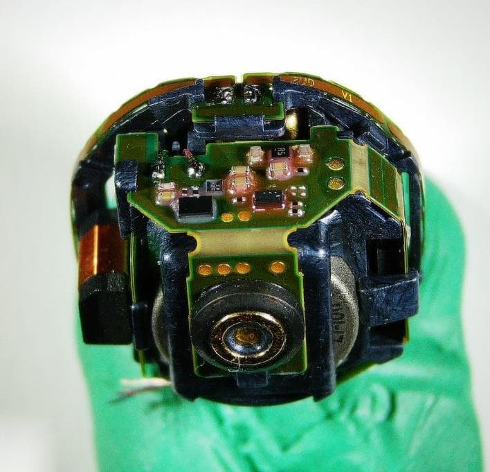
Click to zoom
Application Details
- Equipment Class
- DTS - Digital Transmission System
- Date of Grant
- Sep 23, 2024
- Application Purpose
- Original Equipment
- Date of Application
- Sep 15, 2024
- Equipment Note
- RF Module for Hearing Aids
- Frequency Range
- 2402.00000000 - 2480.00000000
- Company
- WSAUD A/S
- Country
- Denmark
Documents & Files
Document Text
Text extracted from the exhibit documents filed with the FCC. Open a document above to read the original.
Users Manual
Sivantos GmbH - R&D PSA WLS L DE ERL - Richard Rose Page 1 of 3 Erlangen, 2024-08-01 Integration manual for RF Module 9 (RFM009) The “RFM009” radio module contains two radio transceivers running at 3.27 MHz and 2.45 GHz which are implemented in a single hardware platform. The 3.27 MHz radio consists of a nearfield inductive magnetic transceiver. It uses time division duplex and runs on a single channel with phase modulation. The signal is transmitted by a coil antenna. The intended use of this radio is to exchange data between two hearing aids or to communicate with a proprietary accessory. The 2.45 GHz radio is mainly used for Bluetooth® Low Energy Radio communication. In addition to that, the receiver is also capable of proprietary communication modes. The transceiver is connected to a PCB-integrated antenna. The intended use of this radio is to exchange data between hearing aids and Bluetooth accessories. The main part of the module is a set of analog and digital ASICs which contain both radios. These ASICs are mounted on a flex PCB. In addition to that the module comprises the coil antenna for the nearfield inductive magnetic system, one crystal and an EEPROM memory. The antenna for the 2.45 GHz radio is integrated in the flex PCB of the module. The matching circuitry between the radio ASIC and the antenna is also on the flex PCB. On the flex PCB additional components are mounted and connected to the radio module. These include microphones, the connector to the external speaker, push buttons, the telecoil and the battery connector. The system is powered by a lithium ion battery, all necessary voltage regulators are included in the module. The PCB with the module and all other components of the hearing aid are arranged in a plastic frame that is not user serviceable or user modifiable. The outer housing may be replaced by field service, but this is not relevant for the wireless module. The module is thus not installed but instead assembled at the same time as the host is. The position of components and interconnection through the PCB are decided during the project phase for the different hosts and following the best practice of the engineering team in order to assure an optimal integration of the module. Several validation steps are done through the development to assure the full compliance with all the regulatory requirements. Sivantos GmbH - R&D PSA WLS L DE ERL - Richard Rose Page 2 of 3 Erlangen, 2024-08-01 The user guide must contain the HVIN, the FCC ID and the IC ID: HVIN: RFM009 Contains FCC ID: 2AXDT-RFM009 Contains IC ID: 26428-RFM009 and following statements: (English version) This Class B digital apparatus complies with Canadian ICES‑003. Changes or modifications made to this equipment not expressly approved by the legal manufacturer may void the FCC authorization to operate this equipment. This device complies with Part 15 of the FCC Rules and with ISED's licence-exempt RSSs. Operation is subject to the following conditions: • this device may not cause harmful interference, and • this device must accept any interference received, including interference that may cause undesired operation. This equipment has been tested and found to comply with the limits for a Class B digital device, pursuant to Part 15 of the FCC Rules. These limits are designed to provide reasonable protection against harmful interference in a residential installation. This equipment generates, uses and can radiate radio frequency energy and, if not installed and used in accordance with the instructions, may cause harmful interference to radio communications. However, there is no guarantee that interference will not occur in a particular installation. If this equipment does cause harmful interference to radio or television reception, which can be determined by turning the equipment off and on, the user is encouraged to try to correct the interference by one or more of the following measures: • Reorient or relocate the receiving antenna. • Increase the separation between the equipment and receiver. • Connect the equipment to an outlet on a circuit different from that to which the receiver is connected. • Consult the dealer or an experienced radio/TV technician for help. The radiated output power of the device is far below the FCC and ISED radio frequency exposure limits. Sivantos GmbH - R&D PSA WLS L DE ERL - Richard Rose Page 3 of 3 Erlangen, 2024-08-01 For body worn operation, this device has been tested and meets the FCC RF exposure guidelines when used with the legal manufacturer’s accessories supplied or designated for this product. Use of other accessories may not ensure compliance with FCC RF exposure guidelines. (French version) Cet appareil numérique de classe B est conforme à la norme canadienne ICES‑003. Un changement ou une modification apporté à cet appareil sans être expressément approuvé par le fabricant légal peut annuler l'autorisation FCC d'utilisation de l'appareil. Cet appareil est conforme à la partie 15 des règlements FCC et aux normes RSS d'exemption de licence de l'organisme canadien ISDE. Son fonctionnement est soumis aux conditions suivantes : • cet appareil ne doit pas causer d'interférences nuisibles, et • cet appareil doit supporter toutes les interferences reçues, y compris celles susceptibles de perturber son bon fonctionnement. Cet appareil a été testé et déclaré conforme aux valeurs limites d'un appareil numérique de classe B selon la partie 15 des règlements FCC. Ces limites sont destinées à garantir une protection raisonnable contre les interférences nuisibles en milieu résidentiel. Cet appareil génère, utilise et peut rayonner de l'énergie radiofréquence et, s'il n'est pas installé et utilisé dans le respect des instructions, peut produire des interferences nuisibles aux liaisons radio. Cependant, rien ne garantit que ces interférences ne se produiront pas dans une installation particulière. Si cet appareil provoque des interférences nuisibles avec des récepteurs de rad…
Text truncated - open the document above for the full version.
Attestation Statements
WSAudiology WSAUD A/S Nym0llevej 6 3540 Lynge Denmark Federal Communication Commission Authorization and Evaluation Division 7435 Oakland Mills Road Columbia, MD 21046 USA 2024-08-07 Attestation Statement according to 2.911(d)(5)(i) and 2.911(d)(5)(ii) FCC ID: 2AXDT-RFM009 TO WHOM IT MAY CONCERN: Hereby we certify that the equipment for which authorization is sought is not "covered" equipment prohibited from receiving an equipment authorization pursuant to section 2.903 of the FCC rules. Fürther we certify that, as of the date of the filing of the application, WSAUD A/S is not identified on the Covered List as an entity producing "covered" equipment. Sincerely, Dr. Thomas Fischer Senior Director Embedded Software Dr. Heike Heuermann VP R&D Platform Dev. & Managing Dir. Sivantos GmbH Henri-Dunant-Str. 100 91058 Erlangen Germany [email protected] Sivantos GmbH Henri-Dunant-Str. 100 91058 Erlangen Germany [email protected] WSAUD A/S Nymdllevej 6 3540 Lynge Denmark Rhone: +45 44 35 56 00 www.wsa.com
Attestation Statements
WSAudiology WSAUD A/S Nym0llevej 6 3540 Lynge Denmark Federal Communication Commission Authorization and Evaluation Division 7435 Oakland Mills Road Columbia, MD 21046 USA July 10th, 2024 Attestation Statement according to 2.911(d)(7) TO WHOM IT MAY CONCERN: We, WSAUD A/S, designate WS Audiology USA Inc., to act as U.S. agent for Service of process. WS Audiology USA Inc. hereby acknowledges the Obligation of the U.S. agent for Service of process. Fürther WSAUD A/S accepts to maintain an agent for no less than one year after the grantee has terminated all marketing and importation or the conclusion of any Commission- related proceeding involving the equipment. Sincerely WSAUD A/S FRN:0029767068 Nym0llevej 6 3540 Lynge, Denmark Dr. Thomas Fischer Senior Director Embedded Software +49 9131 308 3382 [email protected] WS Audiology USA Inc. FRN: 0033434770 101 Wood Ave Iselin, NJ 08830, United States La-Shaunda Joseph US Regulatory Affairs Manager +1 561 785 9321 [email protected] WSAUDIOLOGY USA, INC. 101 WOOD AVE. ISEUN, NEW JERSEY 08830 UNITED STATES WSAUD A/S Nym0llevej 6 3540 Lynge Denmark Phone: +45 44 35 56 00 www wsa com
Cover Letter(s)
WSAudiology Federal Communication Commission Equipment Authorization Division, Application Processing Branch 7435 Oakland Mills Road Columbia, MD 21048 Certification and Engineering Bureau Innovation, Science and Economic Development Canada Spectrum Engineering Branch 3701 Carling Avenue, Building 94 Ottawa, Ontario K2H 8S2 Name Department E-mail Date Richard Rose Sivantos GmbH R&D PFD WLS C Henri-Dunant-Str. 100 91058 Erlangen Germany [email protected] 2024-09-11 Grantee code: 2AXDT FRN: 0029767068 Company Number: 26428 TO WHOM IT MAY CONCERN Authorization Letter I, Mr. Richard Rose, hereby authorize the following persons below to act on my behalf in all manners relating to applications for equipment authorizations, including signing of all documents relating to these matters. All acts carried out by the persons below on my behalf, shall have the same effect as acts of my own. The authorization is valid for the following persons: Dr. Thomas Fischer Jan Knittel Dr. Heike Heuermann Christian Honsig Spren Mpllskov Larsen Kristine Pedersen The letter is valid for the following time period: unlimited Sincerely, 7c Richard Rose WSAUD A/S Nym0llevej 6 3540 Lynge Denmark Rhone: +45 44 35 56 00 www.wsa.com Page 1 of 1
Cover Letter(s)
WSAudiology Federal Communication Commission Equipment Authorization Division, Application Processing Branch 7435 Oakland Mills Road Columbia, MD 21048 Certification and Engineering Bureau Innovation, Science and Economic Development Canada Spectrum Engineering Branch 3701 Carling Avenue, Building 94 Ottawa, Ontario K2H 8S2 2024-08-07 Modular Transmitter Declaration TO WHOM IT MAY CONCERN Pursuant to KDB Publication 996369 D03 and RSP-100, we, WSAUD A/S, hereby declare and ensure that the modular transmitter FCC Certification Number: IC Certification Number: PMN: Model Name/HVIN: 2AXDT-RFM009 26428-RFM009 RF Module 9 RFM009 will only be used in our own products and is not intended for sale to third parties. The user manual Integration instructions are internal confidential manufacturing documents. Sincerely, Dr. Thomas Fischer Senior Director Embedded Software Sivantos GmbH Henri-Dunant-Str. 100 91058 Erlangen Germany [email protected] VP R&D Platform Dev. & Managing Dir. Sivantos GmbH Henri-Dunant-Str. 100 91058 Erlangen Germany [email protected] WSAUD A/S Nymtfllevej 6 3540 Lynge Denmark Rhone:+45 44 35 56 00 www.wsa.com Page 1 of I
Cover Letter(s)
WSAudiology Federal Communication Commission Equipment Authorization Division, Application Processing Branch 7435 Oakland Mills Road Columbia, MD 21048 Certification and Engineering Bureau Innovation, Science and Economic Development Canada Spectrum Engineering Branch 3701 Carling Avenue, Building 94 Ottawa, Ontario K2H 8S2 Name Department Phone E-mail Website Richard Rose R&D PSA WLS L DE ERL Henri-Dunant-Strasse 100 91058 Erlangen, Germany +49 9131308 3727 [email protected] www.wsa.com Date 2024-08-07 Subject:FCC IISED Modular Approval Statement FCC Certification Number: 2AXDT-RFM009 IC Certification Number: 26428-RFI\/l009 PMN: RF Module 9 Model Name/HVIN: RFM009 TO WHOM IT MAY CONCERN Pursuant to Paragraphs RSP-100, Issue 12 and CFR § 15.212, we herewith declare for our module: Modular approval requirement YesNo (a) The radio elements shall have the radio frequency circuitry shielded. Physical/discrete and tuning capacitors may be located external to the shield but shall be on the module assembly. X The model above referred does not have its own RF shielding. This limitation is one of the reasons why Sivantos requests only the Limited Modular Approval. The module is to be used exclusively by Sivantos, integrated under controlled conditions and always assuring the total emission and immunity are within specifications. The module is a fully integrated radio module for short ränge wireless data exchange, including radio circuitry on board and is intended for Sivantos wireless hearing aids only. Therefore, the module cannot be used directly by end users. The behavior of the wireless module is locked by design and can only be changed by Sivantos, so the compliance of the end product is always ensured. (b) If the module has modulation/data input(s), they shall be buffered in orderte ensure that the module will comply with the requirements set out in the applicable Radio Standards Specification (RSS) and Part 15 under conditions of excessive data rates or over-modulation. X (c) The module shall have its own power supply regulation on the module itself. This is to ensure that the module will comply with the requirements set out in the applicable Standard regardless of the design of the power supplying circuitry in the host product that houses the module. X The wireless parts of the radio module share the power supply with other digital parts, like Digital ASIC. As producer and integrator of the radio module, it is assured that the power supplied will not affect its correct functioning. We apply for a Limited Modular Approval also due to this constraint. WSAUD A/S Nymtfllevej 6 3540 Lynge Denmark Phone: +45 44 35 56 00 www.wsa.com Page l of 2 WSAudiology If you have any questions, please feel free to contact us at the address shown below. (d) The module shall comply with the provisions for external power amplifiers and antennas detailed in the applicable RSS and rule part. The equipment certification application shall contain: i. a detailed description of the configuration of highest antenna gain for each type of transmitting antenna for licence-exempt modules; ii. the maximum transmitting antenna gain for licence modules; and iü. a detailed description of the configuration of lowest antenna gain for each type of receiving antenna for Dynamic Frequency Selection (DFS) modules with removable antenna(s). X (e) The module shall be tested for compliance with the applicable Standard in a stand- alone configuration (i.e., the module shall not be inside another product during testing). X The modular transmitter has been tested integrated on a typical host, a hearing aid Instrument that best represents all the future hosts where the module will be used by WS Audiology. Due to the size limitations of the hearing aid Instruments, the radio module is in the same PCB of the host making impossible to test it on a standalone configuration. (f) The module complies or will comply with applicable RSS-102 exposure requirements and any applicable FCC RF exposure requirement (§§1.1307(b), 1.1310, 2.1091, and 2.1093) in its intended configuration/integration in a host. X (g) The module must be labeled with its permanently affixed label (indicating ISED certification number, HVIN and FCC identifier), or use an electronic display (see KDB Publication 784748 and RSP-100, section 5). X The size of the module is too small for the regulatory FCC/ISED label in its short form to be placed any, which are therefore displayed in the user manual. (h) The module must comply with all specific rules applicable to the transmitter, including all the conditions provided in the integration instructions by the grantee. X Only applicable for FCC certification: (i) The module must contain a permanently attached antenna, or contain a unique antenna connector, and be marketed and operated only with specific antenna(s), per §§ 15.203, 15.204(b), 15.204(c), 15.212(a), 2.929(b). For further information concerning antenna connectors see: DA-00-1087. X Senior Director Embedded Software Dr. Heike Heuermann VP R&D Platform Dev. & Managing Dir. [email protected] [email protected] WSAUO A/S Nym0llevej 6 3540 Lynge Denmark Rhone: +45 44 35 56 00 www.wsa.com Page 2 of 2
Cover Letter(s)
WSAudiology Federal Communication Commission 2024-08-07 Equipment Authorization Division, Application Processing Branch 7435 Oakland Mills Road Columbia, MD 21048 CONFIDENTIAUTY REQUEST for Certification Service in USA TO WHOM IT MAY CONCERN Pursuant to Paragraphs §0.457 and 0.459 of the Commission's Rules (47 C.F.R.) and Section §552(b)(4) of the Freedom of Information Act, we request confidentiality for the following product: Model FCC ID 2AXDT-RFM009 RFM009 For the product stated above, we request permanent confidentiality for exhibits which contain Operational Description, Block Diagram, Schematics, Parts Lists or Tune Up Information. The above exhibits contain our trade secrets and proprietary information that could be of benefit to our competitors. Sincerely, Dr. Thomas Fischer Senior Director Embedded Software Dr. Heike Heuermann VP R&D Platform Dev. & Managing Dir. euermann Sivantos GmbH Henri-Dunant-Str. 100 91058 Erlangen Germany [email protected] Sivantos GmbH Henri-Dunant-Str. 100 91058 Erlangen Germany [email protected] WSAUD A/S Nym0llevej 6 3540 Lynge Denmark Rhone: +45 44 35 56 00 www.wsa.com Page 1 of 1
External Photos
2024-08-28 │ R&D PSA WLS L DE ERL │ W. Pirzer Restricted Integrated Module RFM009 – Host: D12+ Silk Max+ FCC ID: 2AXDT-RFM009 IC: 26428-RFM009 Text
ID Label/Location Info
WSAudiology Manufacturer's Statement FCC ID location justification 2024-08-07 FCC ID: 2AXDT-RFM009 To whom it may concern We, the undersigned, hereby submit the justification for placing the FCC-ID in the associated User Manual for the Hearing Aids containing the module with the above-mentioned FCC-ID. According to KDB Publication 784748 D01, when the device is so small, or for such use that it is impracticable to label with a font size that is four points or larger (and the device does not utilize electronic labeling), then the FCC-ID shall be placed in the User Manual and the device packaging or on a removable label attached to the device. Hearing Aids having the above-mentioned FCC-ID are so small and considering the dimensions of the equipment and the label area, it is impracticable to label FCC-ID with a font size required on the devices. Therefore, the FCC-ID label is placed in the User Manual of the end product. Instruction for module Integration regarding the FCC-ID labelling is included in the Integration manual. If you have any questions, feel free to contact us at the address shown above. Yours sincerely, Dr. Thomas Fischer Senior Director Embedded Software Dr. Heike Heuermann VP R&D Platform Dev. & Managing Dir. [email protected] [email protected] WSAUD A/s Nymallevej 6 3540 Lynge Denmark www.wsa.com Rhone: +45 44 35 56 00
Internal Photos
2024-08-28 │ R&D PSA WLS L DE ERL │ W. Pirzer Restricted Module pictures RFM009 – Host: D12+ Silk Max+ FCC ID: 2AXDT-RFM009 IC: 26428-RFM009 Text
RF Exposure Info
© cetecom advanced GmbH Page 1 of 3 RF Exposure Evaluation according to KDB 447498 D01 v06 Report identification number: 1-7412_23-01-06_TR1-R01_SAR_FCC Certification numbers and labeling requirements FCC ID 2AXDT-RFM009 This test report is electronically signed and valid without handwritten signature. For verification of the electronic signatures, the public keys can be requested at the testing laboratory. Document authorised: Alexander Hnatovskiy Eric Tuettmann Lab Manager Testing Manager Radio Labs Radio Labs Report no.: 1-7412_23-01-06_TR1-R01 © cetecom advanced GmbH Page 2 of 3 1. SAR test exclusion (KDB 447498 D01 General RF Exposure Guidance v06) 4.3.1. Standalone SAR test exclusion considerations Unless specifically required by the published RF exposure KDB procedures, standalone 1-g head or body and 10-g extremity SAR evaluation for general population exposure conditions, by measurement or numerical simulation, is not required when the corresponding SAR Test Exclusion Threshold condition(s), listed below, is (are) satisfied. These test exclusion conditions are based on source-based time-averaged maximum conducted output power of the RF channel requiring evaluation, adjusted for tune-up tolerance, and the minimum test separation distance required for the exposure conditions. The minimum test separation distance defined in 4.1 f) is determined by the smallest distance from the antenna and radiating structures or outer surface of the device, according to the host form factor, exposure conditions and platform requirements, to any part of the body or extremity of a user or bystander. To qualify for SAR test exclusion, the test separation distances applied must be fully explained and justified, typically in the SAR measurement or SAR analysis report, by the operating configurations and exposure conditions of the transmitter and applicable host platform requirements, according to the required published RF exposure KDB procedures. When no other RF exposure testing or reporting are required, a statement of justification and compliance must be included in the equipment approval, in lieu of the SAR report, to qualify for SAR test exclusion. When required, the device specific conditions described in the other published RF exposure KDB procedures must be satisfied before applying these SAR test exclusion provisions; for example, handheld PTT two-way radios, handsets, laptops and tablets, etc. a) For 100 MHz to 6 GHz and test separation distances ≤ 50 mm, the 1-g and 10-g SAR test exclusion thresholds are determined by the following: [(max. power of channel, including tune-up tolerance, mW) / (min. test separation distance, mm)] · [√f (GHz) ] ≤ 3.0 for 1-g SAR, and ≤ 7.5 for 10-g extremity SAR, where • f (GHz) is the RF channel transmit frequency in GHz • Power and distance are rounded to the nearest mW and mm before calculation • The result is rounded to one decimal place for comparison • The values 3.0 and 7.5 are referred to as numeric thresholds in step b) below The test exclusions are applicable only when the minimum test separation distance is ≤ 50 mm, and for transmission frequencies between 100 MHz and 6 GHz. When the minimum test separation distance is < 5 mm, a distance of 5 mm according to 4.1 f) is applied to determine SAR test exclusion. b) For 100 MHz to 6 GHz and test separation distances > 50 mm, the 1-g and 10-g SAR test exclusion thresholds are determined by the following (also illustrated in Appendix B): 1) {[Power allowed at numeric threshold for 50 mm in step a)] + [(test separation distance – 50 mm)·(f (MHz) /150)]} mW, for 100 MHz to 1500 MHz 2) {[Power allowed at numeric threshold for 50 mm in step a)] + [(test separation distance – 50 mm)·10]} mW, for > 1500 MHz and ≤ 6 GHz c) For frequencies below 100 MHz, the following may be considered for SAR test exclusion (also illustrated in Appendix C): 1) For test separation distances > 50 mm and < 200 mm, the power threshold at the corresponding test separation distance at 100 MHz in step b) is multiplied by [1 + log(100/f (MHz) )] 2) For test separation distances ≤ 50 mm, the power threshold determined by the equation in c) 1) for 50 mm and 100 MHz is multiplied by ½ 3) SAR measurement procedures are not established below 100 MHz. Report no.: 1-7412_23-01-06_TR1-R01 © cetecom advanced GmbH Page 3 of 3 2. EUT technologies Declared minimum safety distance: 5 mm f Min f Max #P co nd P E IRP P RF E xp P Result P Limit % BT LE 24022480A4.22.14.22.633.1882.84% SRD3.273.27B-12.00-12.00-12.00.06196.490.03% SRD Technology Frequency [MH z] Reference Power [mW] Share of Limit Output Power [dBm ] Notes: - Max rated conducted output power taken from customer’s tune up info 3.27MHz0.03% BT LE82.84% Technology Share of Limit Sum82.88% Referenced Documents: # Results from: A Test Report 1-7412_23-01-04_TR1-R01 B Test Report 1-7412_23-01-05_TR1-R01 3. Conclusion This prediction demonstrates the following: The power density levels for FCC at a distance of 5 mm are below the maximum levels allowed by regulations. Conclusion: RF exposure evaluation is not required.
Test Report
Antenna Datasheet – RFM009 – Host: D12+ Silk Max+ 1 Information Antenna TypePCB – Internal Antenna Frequency (MHz)240224402480 Conducted Power (dBm)3.74.2-2.1 EIRP (dBm)1.91.4-8.0 Gain (dBi)-1.8-2.8-5.9 Where Gain = EIRP – Conducted Power 2 Antenna Location The Antenna is bended and soldered on the PCB of the hearing aid as shown in the following pictures: Antenna 3 Antenna Radiation Pattern 2402 MHz 2440 MHz 2480 MHz
Test Report
Conducted test results No.1-7412/24-01-05_TR1-A201-R1 February 28, 2024 Test Standard(s)FCC 15.247 - NI FCC 15.247, ISED RSS247 - NI NA - NI This document is electronically signed and valid without handwritten signature. Public keys for verification of the electronic signatures can be requested at the testing laboratory. Authorized Michael Dorongovski Lab Manager Radio Labs cetecom advanced GmbH Untertürkheimer Str. 6-10, 66117 Saarbrücken Document No. 1-7412/24-01-05_TR1-A201-R1 Release 1 - Page 1 of 82 Table of Content FCC 15.247 # Bandwidth 6dB DTS ~ BT LE 1 Msps3 FCC 15.247 # Bandwidth 6dB DTS ~ BT LE 2 Msps8 FCC 15.247, ISED RSS247 # Bandwidth 99PCT and 20dB ~ BT LE 1 Msps13 FCC 15.247, ISED RSS247 # Bandwidth 99PCT and 20dB ~ BT LE 2 Msps24 FCC 15.247 # Maximum peak conducted output power DTS ~ BT LE 1 Msps35 FCC 15.247 # Maximum peak conducted output power DTS ~ BT LE 2 Msps43 FCC 15.247 # Peak psd DTS ~ BT LE 1 Msps51 FCC 15.247 # Peak psd DTS ~ BT LE 2 Msps56 FCC 15.247 # TX spurious conducted 20dBc ~ BT LE 1 Msps61 FCC 15.247 # TX spurious conducted 20dBc ~ BT LE 2 Msps69 NA # Peak output power 3MHz/3MHz ~ BT LE 1 Msps77 cetecom advanced GmbH Untertürkheimer Str. 6-10, 66117 Saarbrücken Document No. 1-7412/24-01-05_TR1-A201-R1 Release 1 - Page 2 of 82 FCC 15.247 # Bandwidth 6dB DTS ~ BT LE 1 Msps References TC start15.02.2024 16:10:53 Ambit temp [°C] | humidity [rel%] 25.8 | 36 System version5.0.1.2 Standard | Version FCC 15.247 | NI Method DescriptionFCC 15.247 Bandwidth 6dB DTS - BT LE 1 Msps Information EUT Common Settings BT Low Energy Intermodulation Value N 3 Image Freq. Low | Mid | High [MHz] 0 | 0 | 0 Power Class2 1 Mbps supported True | TXpayload 255 | RXpayload 255 2 Mbps supported True | TXpayload 255 | RXpayload 255 Longrange S8 supported True | TXpayload 255 | RXpayload 255 Longrange S2 supportedTrue | TXpayload 255 | RXpayload 255 Signaling Settings USB_RS232 | TWO | 10 | 2400 | None | S1 | None | On Signaling RF Settings RF1com | 0 | 0 | On | User Interaction No Equipment Signal analyzer,Rohde&Schwarz,FSV-30,1321.3008K30/103170,3.60 Signaling unit,Rohde&Schwarz,CMW,1201.0002k75/102550,4.0.190 Switch matrix,cetecom advanced GmbH,USM,A001,1.0.0 Power supply,HAMEG,HMP2020,026640516,HW50010002/SW2.51 Test Parameter Technology to testBT LE 1 Msps EUT portEUT1 Temperaturenom Voltagenom Frequency low to testTrue | Freq [MHz] 2402 Frequency mid to testTrue | Freq [MHz] 2440 Frequency high to testTrue | Freq [MHz] 2480 Auto control enabled power supply | Climatic Box Yes | No Additional path loss [dB]0.5 cetecom advanced GmbH Untertürkheimer Str. 6-10, 66117 Saarbrücken Document No. 1-7412/24-01-05_TR1-A201-R1 Release 1 - Page 3 of 82 Test Parameter Full path typeEUT_SA_GEN_SIG Full path nameEUT1.MP.SIG1/EUT1.SA/EUT1.GEN1/EUT1.GEN2/ Switch bits 00010001:00010001:00000000:00000001 cetecom advanced GmbH Untertürkheimer Str. 6-10, 66117 Saarbrücken Document No. 1-7412/24-01-05_TR1-A201-R1 Release 1 - Page 4 of 82 Test at TX 2402 MHz RESULT: Reference power cond. DESCRIPTIONLOWER LIMITUPPER LIMITMEASUREDUNITVERDICT Ref. power 1MHz/1MHz cond. ------4.01dBmINFO Ref. frequency------2402.300MHzINFO READ SA SETTINGS: RefLevel [dBm] | RefLevelOffset [dB] | InpAtt [dB]9.01 | 8.76 | 20 Start [MHz] | Stop [MHz]2401.000 | 2403.000 RBW [MHz] | VBW [MHz]0.100000 | 0.300000 Detector | TraceModePOS | MAXH Sweep: time [ms] | count | points per Section | type50 | 200 | 10001 | SWE 2401.002401.202401.402401.602401.802402.002402.202402.402402.602402.802403.00 MHz Frequency 10.0 5.0 0.0 -5.0 -10.0 -15.0 -20.0 -25.0 -30.0 dBm M agnitude BW 6dB RESULT DESCRIPTIONLOWER LIMITUPPER LIMITMEASUREDUNITVERDICT DTS bandwidth (6dB)500---653kHzPASS cetecom advanced GmbH Untertürkheimer Str. 6-10, 66117 Saarbrücken Document No. 1-7412/24-01-05_TR1-A201-R1 Release 1 - Page 5 of 82 Test at TX 2440 MHz RESULT: Reference power cond. DESCRIPTIONLOWER LIMITUPPER LIMITMEASUREDUNITVERDICT Ref. power 1MHz/1MHz cond. ------3.73dBmINFO Ref. frequency------2440.300MHzINFO READ SA SETTINGS: RefLevel [dBm] | RefLevelOffset [dB] | InpAtt [dB]8.73 | 8.8 | 15 Start [MHz] | Stop [MHz]2439.000 | 2441.000 RBW [MHz] | VBW [MHz]0.100000 | 0.300000 Detector | TraceModePOS | MAXH Sweep: time [ms] | count | points per Section | type50 | 200 | 10001 | SWE 2439.002439.202439.402439.602439.802440.002440.202440.402440.602440.802441.00 MHz Frequency 10.0 5.0 0.0 -5.0 -10.0 -15.0 -20.0 -25.0 -30.0 dBm M agnitude BW 6dB RESULT DESCRIPTIONLOWER LIMITUPPER LIMITMEASUREDUNITVERDICT DTS bandwidth (6dB)500---652kHzPASS cetecom advanced GmbH Untertürkheimer Str. 6-10, 66117 Saarbrücken Document No. 1-7412/24-01-05_TR1-A201-R1 Release 1 - Page 6 of 82 Test at TX 2480 MHz RESULT: Reference power cond. DESCRIPTIONLOWER LIMITUPPER LIMITMEASUREDUNITVERDICT Ref. power 1MHz/1MHz cond. -------2.01dBmINFO Ref. frequency------2480.300MHzINFO READ SA SETTINGS: RefLevel [dBm] | RefLevelOffset [dB] | InpAtt [dB]2.99 | 8.9 | 10 Start [MHz] | Stop [MHz]2479.000 | 2481.000 RBW [MHz] | VBW [MHz]0.100000 | 0.300000 Detector | TraceModePOS | MAXH Sweep: time [ms] | count | points per Section | type50 | 200 | 10001 | SWE 2479.002479.202479.402479.602479.802480.002480.202480.402480.602480.802481.00 MHz Frequency 0.0 -5.0 -10.0 -15.0 -20.0 -25.0 -30.0 -35.0 -40.0 dBm M agnitude BW 6dB RESULT DESCRIPTIONLOWER LIMITUPPER LIMITMEASUREDUNITVERDICT DTS bandwidth (6dB)500---653kHzPASS Verdict PASS cetecom advanced GmbH Untertürkheimer Str. 6-10, 66117 Saarbrücken Document No. 1-7412/24-01-05_TR1-A201-R1 Release 1 - Page 7 of 82 FCC 15.247 # Bandwidth 6dB DTS ~ BT LE 2 Msps References TC start15.02.2024 16:57:52 Ambit temp [°C] | humidity [rel%] 28.3 | 32 System version5.0.1.2 Standard | Version FCC 15.247 | NI Method DescriptionFCC 15.247 Bandwidth 6dB DTS - BT LE 2 Msps Information EUT Common Settings BT Low Energy Intermodulation Value N 3…
Text truncated - open the document above for the full version.
Contact Information
Applicant
Richard Rose
Test Firm
cetecom advanced GmbHGerald Schmidt
Technical Specifications
| # | Rule Parts | Frequency Range | Power Output |
|---|---|---|---|
| 1 | 15C | 2.40 GHz - 2.48 GHz | 2.63 mW |
Other Applications from WSAUD A/S
2AXDT-RFM030
Aug 18, 2026RF Module for Hearing Aids
Equipment Class
DXX - Part 15 Low Power Communication Device Transmitter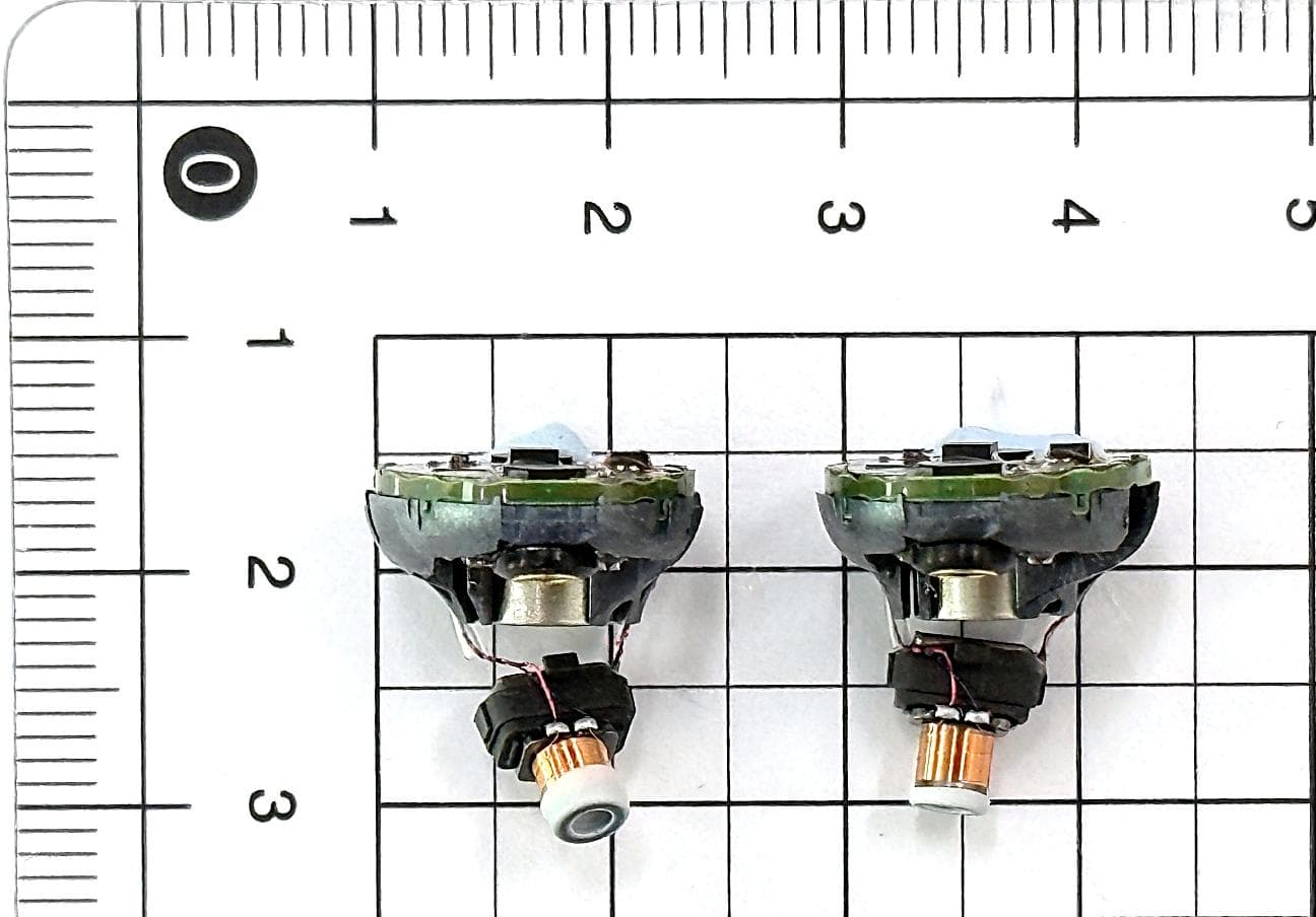
2AXDT-RFM022
Jul 15, 2026RF Module for Hearing Aids
Equipment Class
DXX - Part 15 Low Power Communication Device Transmitter2AXDT-RFM016
Sep 08, 2025RF Module for Hearing Aids
Equipment Class
DTS - Digital Transmission System2AXDT-RFM015
Oct 03, 2024RF Module for Hearing Aids
Equipment Class
DXX - Part 15 Low Power Communication Device Transmitter
2AXDT-TV2
Sep 30, 2024TV streaming adapter
Equipment Class
DTS - Digital Transmission System