2AXF5-VERMEER12.4 GHz FHSS Wireless Module
Vermeer Manufacturing Company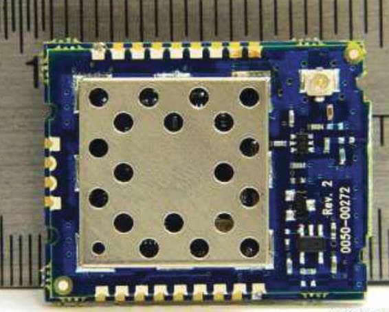
Click to zoom
Application Details
- Equipment Class
- DSS - Part 15 Spread Spectrum Transmitter
- Date of Grant
- Feb 22, 2021
- Application Purpose
- Original Equipment
- Date of Application
- Feb 16, 2021
- Equipment Note
- 2.4 GHz FHSS Wireless Module
- Frequency Range
- 2404.00000000 - 2466.90000000
- Country
- United States
Documents & Files
Document Text
Text extracted from the exhibit documents filed with the FCC. Open a document above to read the original.
Users Manual
Datasheet RADIO APPARATUS – RAMP Wireless Module 2.4 GHz FHSS Wireless Module Version 1.2 REVISION HISTORY Version Date Notes Approver 1.1 2020 11 23 Initial Release J Bond 1.2 2020 12 21 Update RFX information J Bond CONTENTS 1 RAMP MODULES ................................................................................... 4 1.1 KEY FEATURES .................................................................................. 4 1.2 PIN DEFINITIONS ................................................................................ 7 1.3 INPUT CHARACTERISTICS .................................................................... 9 1.4 OUTPUT CHARACTERISTICS ................................................................ 9 1.5 BLOCK DIAGRAM .............................................................................. 10 1.6 TIMING SPECIFICATIONS ................................................................... 10 1.7 RF HOP FRAME ................................................................................ 11 2 HARDWARE INTERFACE .................................................................... 12 2.1 PIN DESCRIPTIONS ........................................................................... 12 3 REFLOW PARAMETERS ..................................................................... 14 4 ORDERING INFORMATION.................................................................. 15 4.1 PRODUCT PART NUMBERS ................................................................ 15 5 REGULATORY INFORMATION ............................................................ 15 5.1 FCC/IC REQUIREMENTS FOR MODULAR APPROVAL .......................................................................................... 15 RAMP Modules Vermeer Corporation RAMP (Range Amplified MultiPoint) modules are designed to provide robust wireless communications for any number of applications requiring a wireless transport for serial data. RAMP modules feature a Frequency Hopping Spread Spectrum (FHSS) protocol for excellent interference and multipath immunity. RAMP modules server/client architecture allows for more than 16 million clients to be addressed and communicating within the network. This document contains information about the hardware and software interface between a Vermeer Corporation RADIO APPARATUS transceiver and a host. Information includes the theory of operation, specifications, and interface definitions. Note: Unless mentioned specifically by name, the RADIO APPARATUS modules are referred to as module, radio, or transceiver. Individual naming is used to differentiate product specific features. The host (PC/microcontroller/any device to which the RADIO APPARATUS module is connected) is referred to as OEM host or host. Key Features ▪ Retries and acknowledgements ▪ Configurable network parameters ▪ Multiple generic I/O ▪ 280 kbps or 500 kbps RF data stream ▪ Idle current draw of 9.5 mA, sleep current of <1 uA (varies depending on sleep mode) ▪ Software-selectable interface baud ranging from 1200 bps to 230.4 kbps ▪ Upgradable FW through serial port ▪ Low cost, low power, and small size ideal for high volume, portable, and battery powered applications ▪ All modules are qualified for Industrial temperatures (-40°C to 85°C) Table 1: Specifications table General Form Factor SMD-ANT+U.FL, Pluggable-ANT+U.FL, SMD-U.FL, Pluggable-U.FL Antenna External antenna through U.FL connector Serial Interface Data Rate Baud rates from 1200 to 230400. Non-standard baud rates are also supported. Channels 10 mW – 42 selectable channels Security Channelization, System ID, Vendor ID, and Extended System ID Minimum Flash (EEPROM) Memory Endurance 1000 Write/Erase cycles Transceiver Frequency Band 2400-2483.5 MHz RF Data Rate (Raw) 280 kbps or 500 kbps selectable Hop Bin Spacing 900 kHz over 79 hops 1500 kHz over 43 hops RF Technology Frequency Hopping Spread Spectrum Modulation MSK Maximum Output Power Conducted 1 +10 dBm Supply Voltage 2.3-3.6 V ± 50 mV ripple Current Draw Mode Tx Burst 40 mA Rx Active 36 mA Idle Current 9.5 mA PM2/Cyclic Sleep 0.9 μA PM3/Deep Sleep 0.38 μA Receiver Sensitivity (1% PER) RF Profile Receiver Sensitivity (dBm) (1% PER) 500 kbps -88 280 kbps -92 FEC 500 kbps -91 (See Note 5) FEC 280 kbps -95 (See Note 5) *See Note 6 Range (based on external 2.0 dBi antenna at 280 kbps RF data rate) 2 Outdoor (line- of-sight) Indoor (estimated) 10 mW 1.0 km (0.6 miles) 100 m (328 feet) Environmental Temperature (Operational) -40°C to 85°C Temperature (Storage) -50°C to 150°C Physical SMD-U.FL Dimensions 25.4 mm x 32.4 mm x 3.6 mm (1.0” x 1.28” x 0.14”) Pluggable-U.FL Dimensions 26.7 mm x 33 mm x 10.6 mm (1.05” x 1.29” x 0.42”) Certifications FCC – Part 15.247 2AXF5-VERMEER1 Industry Canada (IC) 26431-VERMEER1 RoHS Yes Notes: 1. See Regulatory Information in this guide. 2. While the use of FEC does not affect the actual PER, it does allow correct reception at a lower SNR, thus extending communication range. We’ve measured this to yield an effective sensitivity increase on the order of 3dBm. 3. The RADIO APPARATUS can operate at two different RF baud rates: 250 kbps and 500 kbps. The chip receiver saturation is -11dBm at 250 kbps and -15 dBm at 500 kbps. Inside the module, there is an FEM which has net gain of about 11-13dB. For 500 kbps RF baud rate, the input RF signal must be less than -28 dBm without causing any saturation, and at 250 kbps RF baud rate the signal must be less than -24dbm. In real deployment, some margin to cover the signal variation is required. With all these factors considered, we suggest the received RF signal should not be stronger than -40 dBm. Pin Definitions Table 2: RADIO APPARATUS pins SMT Pin Plugga ble Pin Ty pe Signal Name Functions 1 7 O GIO-0 Generic Output / Hop_Frame 2 6 O GIO_1 Generic Output 3 8 DNC Do Not Connect 4 17 O GIO_2 RS485 Driver Enable 5 19 O GIO_3 PWM Output 6 3 I RXD Asynchronous serial data input to transceiver 7 2 O TXD Asynchronous serial data output from transceiver 8 10 …
Text truncated - open the document above for the full version.
Cover Letter(s)
Request for Modular/Limited Modular Approval Date: January 19, 2021 Subject: Manufacturer’s Declaration for ☐ - Modular Approval ☐ - Split Modular Approval ☒ - Limited Modular Approval ☐ - Limited Split Modular Approval Confidentiality Request for: 2AXF5-VERMEER1 8 Basic Requirements – FCC Part 15.212(a)(1) For Items Marked “NO(*)”, the Limited Module Description Must be Filled Out on the Following Pages Modular Approval Requirement Requirement Met 1. The modular transmitter must have its own RF shielding. This is intended to ensure that the module does not have to rely upon the shielding provided by the device into which it is installed in order for all modular transmitter emissions to comply with FCC limits. It is also intended to prevent coupling between the RF circuitry of the module and any wires or circuits in the device into which the module is installed. Such coupling may result in non-compliant operation. The physical crystal and tuning capacitors may be located external to the shielded radio elements. 15.212(a)(1)(i) ☒ - YES ☐ - NO(*) Details: The module contains a metal shield which covers all RF components and circuitry. The shield is located on the top of the board next to antenna connector 2. The modular transmitter must have buffered modulation/data inputs (if such inputs are provided) to ensure that the module will comply with FCC requirements under conditions of excessive data rates or over-modulation. 15.212(a)(1)(ii) ☒ - YES ☐ - NO(*) Details: Data to the modulation circuit is buffered as described in the operational description provided with the application. 3. The modular transmitter must have its own power supply regulation on the module. This is intended to ensure that the module will comply with FCC requirements regardless of the design of the power supplying circuitry in the device into which the module is installed. 15.212(a)(1)(iii) ☒ - YES ☐ - NO(*) Details: The module contains its own power supply regulation. Please refer to schematic filed with this application. 4. The modular transmitter must comply with the antenna and transmission system requirements of §§ 15.203, 15.204(b), 15.204(c), 15.212(a), and 2.929(b). The antenna must either be permanently attached or employ a ‘‘unique’’ antenna coupler (at all connections between the module and the antenna, including the cable). The ‘‘professional installation’’ provision of § 15.203 is not applicable to modules but can apply to limited modular approvals under paragraph 15.212(b). 15.212(a)(1)(iv) ☒ - YES ☐ - NO(*) Details: The module connects to its antenna using an UFL connector which is considered a non-standard connector. A list of antennas tested and approved with this device may be found in users manual provided with the application. 5. The modular transmitter must be tested in a stand-alone configuration, i.e., the module must not be inside another device during testing. This is intended to demonstrate that the module is capable of complying with Part 15 emission limits regardless of the device into which it is eventually installed. Unless the transmitter module will be battery powered, it must comply with the AC line conducted requirements found in Section 15.207. AC or DC power lines and data input/output lines connected to the module must not contain ferrites, unless they will be marketed with the module (see Section 15.27(a)). The length of these lines shall be length typical of actual use or, if that length is unknown, at least 10 centimeters to insure that there is no coupling between the case of the module and supporting equipment. Any accessories, peripherals, or support equipment connected to the module during testing shall be unmodified or commercially available (see Section 15.31(i)). 15.212(a)(1)(v) ☒ - YES ☐ - NO(*) Details: The module was tested stand-alone as shown in test setup photographs filed with this application. Modular Approval Requirement Requirement Met 6. The modular transmitter must be labeled with its own FCC ID number, or use an electron display (see KDB Publication 784748). If using a permanently affixed label with its own FCC ID number, if the FCC ID is not visible when the module is installed inside another device, then the outside of the device into which the module is installed must also display a label referring to the enclosed module. This exterior label can use wording such as the following: “Contains Transmitter Module FCC ID: XYZMODEL1” or “Contains FCC ID: XYZMODEL1.” Any similar wording that expresses the same meaning may be used. The Grantee may either provide such a label, an example of which must be included in the application for equipment authorization, or, must provide adequate instructions along with the module which explain this requirement. In the latter case, a copy of these instructions must be included in the application for equipment authorization. If the modular transmitter uses an electronic display of the FCC identification number, the information must be readily accessible and visible on the modular transmitter or on the device in which it is installed. If the module is installed inside another device, then the outside of the device into which the module is installed must display a ☒ - YES ☐ - NO(*) label referring to the enclosed module. This exterior label can use wording such as the following: “Contains FCC certified transmitter module(s).” Any similar wording that expresses the same meaning may be used. The user manual must include instructions on how to access the electronic display. A copy of these instructions must be included in the application for equipment authorization. 15.212(a)(1)(vi) Details: There is a label on the module as shown in the labeling exhibit filed with this application. Host specific labeling instructions are shown in the installation manual .filed with this application. 7. The modular transmitter must comply with all specific rule or operating requirements applicable to the transmitter, including all the conditions prov…
Text truncated - open the document above for the full version.
Cover Letter(s)
Request for Confidentiality Date: October 21, 2020 Subject: Confidentiality Request for: FCC ID: 2AXF5-VERMEER1 & IC: 26431-VERMEER1 Pursuant to FCC 47 CFR 0.457(d) and 0.459 and IC RSP-100, Section 9.4, the applicant requests that a part of the subject FCC application be held confidential. Type of Confidentiality Requested Exhibit ☐ Short Term ☒ Permanent Block Diagrams ☐ Short Term External Photos ☐ Short Term ☐ Permanent * 1 Internal Photos ☐ Short Term ☒ Permanent Operation Description/Theory of Operation ☐ Short Term ☐ Permanent Parts List & Placement/BOM ☐ Short Term ☐ Permanent Tune-Up Procedure ☐ Short Term ☒ Permanent Schematics ☐ Short Term Test Setup Photos ☐ Short Term ☐ Permanent * 2 User’s Manual Vermeer Manufacturing Company has spent substantial effort in developing this product and it is one of the first of its kind in industry. Having the subject information easily available to "competition" would negate the advantage they have achieved by developing this product. Not protecting the details of the design will result in financial hardship. Permanent Confidentiality: The applicant requests the exhibits listed above as permanently confidential be permanently withheld from public review due to materials that contain trade secrets and proprietary information not customarily released to the public. Short-Term Confidentiality: The applicant requests the exhibits selected above as short term confidential be withheld from public view for a period of ___(specify number of days not to exceed 180) 2 ___ days from the date of the Grant of Equipment Authorization and prior to marketing. This is to avoid premature release of sensitive information prior to marketing or release of the product to the public. Applicant is also aware that t hey are responsible to notify ACB in the event information regarding the product or the product is made available to the public before the requested period has expired. ACB will then release the documents listed above for public disclosure pursuant to FCC Public Notice DA 04-1705. NOTE for Industry Canada Applications: 1 - The asterisked items (*) require further information to be provided to ACB before permanent confidentiality will be extended to these exhibits. Please refer to FCC KDB 726920 and the specific Document link for D01 found at: https://apps.fcc.gov/oetcf/kdb/forms/FTSSearchResultPage.cfm?switch=P&id=41731 and review section II, 3) regarding specific information that must accompany these requests. 2 - Please refer to http://acbcert.com/documents/misc-docs/Memo-Short-Term-Vs-Standard- Confidentiality.pdf for complete details. IC currently only distinguishes Permanent Confidentiality exhibits as shown above. Short Term confidentiality is not considered applicable to IC applications.
Cover Letter(s)
RE: Vermeer Manufacturing Company FCC ID: 2AXF5-VERMEER1 IC: 26431-VERMEER1 ATCB026101 1.Please note that the response to comment 3f regarding the red-trace emissions shown in the plot on p.40 of the report (see below) is not yet sufficient. I note that the text added to the report shows that the red-trace emissions are not necessarily failing emissions, as they may be attributable to non-tx circuitry, and the higher Class A digital device limits are applicable to them. However, it is not entirely clear that these digital device emissions are not potentially hiding an emission from the tx circuitry that is failing the 15.209 limit - please note that there are restricted bands both in the vicinity of the red-trace emissions in the first graticule from the left (30 – 47 MHz) located at 37.5 – 38.25 MHz, and also in the vicinity of the two red-trace emissions in the third graticule from the left (64 – 81 MHz) located at 73 – 74.6 MHz and 74.8 – 75.2 MHz. If any of the red-trace emissions fall within these restricted bands, then additional information confirming that the emissions do not originate in the transmitter circuitry should be provided – please address (you may have to reduce the RBW so as to be able to resolve the emissions’ exact locations with respect to the restricted band frequencies), and note that this is not simply turning off the transmitter’s output, as doing that leaves the majority of the tx circuitry powered up, and any emissions originating in the transmitter portion of the EUT are subject to 15.209 limits, not just the final output... some additional steps in confirming the source of those emissions would be needed. I also note that the additional plot referenced in the response does not appear to have actually been added to the report – please revise the report to also include it. Response: Please see the revised report (V7). The plot is now present. The devkit that we had tested originally featured a USB connection to a laptop connected outside the test volume. We re-visited this range with a second devkit connected to an AC adapter for this second plot, to demonstrate the emissions over this range.
External Photos
EXTERNAL PHOTOS Company Name Vermeer Manufacturing Company HVIN # VERMEER1 FCC ID # 2AXF5-VERMEER1 IC # 26431-VERMEER1 Page 1 of 6 Surface Mount (312000283) EXTERNAL PHOTOS Company Name Vermeer Manufacturing Company HVIN # VERMEER1 FCC ID # 2AXF5-VERMEER1 IC # 26431-VERMEER1 Page 2 of 6 Pluggable Through Hole (312000284) EXTERNAL PHOTOS Company Name Vermeer Manufacturing Company HVIN # VERMEER1 FCC ID # 2AXF5-VERMEER1 IC # 26431-VERMEER1 Page 3 of 6 Top side pluggable adapter stand Bottom side adapter stand Side view EXTERNAL PHOTOS Company Name Vermeer Manufacturing Company HVIN # VERMEER1 FCC ID # 2AXF5-VERMEER1 IC # 26431-VERMEER1 Page 4 of 6 Antennas Laird Connectivity TRA6927M3PBN-001 PCTEL PCTCN24005 Laird Connectivity TRAB24003P EXTERNAL PHOTOS Company Name Vermeer Manufacturing Company HVIN # VERMEER1 FCC ID # 2AXF5-VERMEER1 IC # 26431-VERMEER1 Page 5 of 6 PCTEL BMLPV2400NGP Nearson S181FL-5(178)-PX-2450 EXTERNAL PHOTOS Company Name Vermeer Manufacturing Company HVIN # VERMEER1 FCC ID # 2AXF5-VERMEER1 IC # 26431-VERMEER1 Page 6 of 6 Laird Connectivity MAF94045 Molex 2.4/5GHz Balance Flex Antenna
ID Label/Location Info
Pluggable Through Hole Label Placement Surface Mount Label Placement 36. 36. A .5 .5 LEBAL ETIHW NO TNIRP KCALB :ROLOC .1 SSOLG :HSINIF .2 TNAILPMOC SHOR EB TSUM .3 GNIKCAB HTIW EVISEHDA-FLES .4 TIGID 2/RAEY TIGID 2 :EDOC ETAD KEEW EGAP FO NCE EGNAHC YB ETAD VER EGNAHC NOITPIRCSED 521 845145692 ZD 31-01-0202 948572 ZD A 1 1 31-01-0202 NOITPIRCSED REBMUN METI YB NGISED ETAD STI DNA TNEMUCOD SIHT :ECITON FO YTREPORP EHT ERA STNETNOC .S.U STI RO NOITAROPROC REEMREV RO ESU ON .SEINAPMOC DETAILIFFA TUOHTIW EDAM EB YAM SEIPOC MORF SNOISSIMREP NETTIRW .NOITAROPROC REEMREV NOITCEJORP ELGNA DR3 .BUSSCEPS LTAM NOITCUDORP OT ESAELER GNIWARD ELACS TON OD .ON METIREBMUN TRAPNOITPIRCSED.YTQ 1745145692DI CCF 420MR ,KNALB LEBAL1 845145692 382000213 ELUDOM ,CCF ,LACED sbl 00.0 = thgieW etamixorppA DEIFICEPS ESIWREHTO SSELNU SEHCNI NI ERA SNOISNEMID 9002 - 5.41Y EMSA OT TERPRETNI 001-A - 3 - 3 SPW SECNARELOT DRADNATS X .X XX .X XXX .X .MID.CARF SELGNA HSINIF ECAFRUS 060. ± 030. ± 010. ± 23/1 ± 1 ± 36. 36. A .5 .5 LEBAL ETIHW NO TNIRP KCALB :ROLOC .1 SSOLG :HSINIF .2 TNAILPMOC SHOR EB TSUM .3 GNIKCAB HTIW EVISEHDA-FLES .4 TIGID 2/RAEY TIGID 2 :EDOC ETAD KEEW EGAP FO NCE EGNAHC YB ETAD VER EGNAHC NOITPIRCSED 521 945145692 ZD 31-01-0202 948572 ZD A 1 1 31-01-0202 NOITPIRCSED REBMUN METI YB NGISED ETAD STI DNA TNEMUCOD SIHT :ECITON FO YTREPORP EHT ERA STNETNOC .S.U STI RO NOITAROPROC REEMREV RO ESU ON .SEINAPMOC DETAILIFFA TUOHTIW EDAM EB YAM SEIPOC MORF SNOISSIMREP NETTIRW .NOITAROPROC REEMREV NOITCEJORP ELGNA DR3 .BUSSCEPS LTAM NOITCUDORP OT ESAELER GNIWARD ELACS TON OD .ON METIREBMUN TRAPNOITPIRCSED.YTQ 1745145692DI CCF 420MR ,KNALB LEBAL1 945145692 482000213 ELUDOM ,CCF ,LACED sbl 00.0 = thgieW etamixorppA DEIFICEPS ESIWREHTO SSELNU SEHCNI NI ERA SNOISNEMID 9002 - 5.41Y EMSA OT TERPRETNI 001-A - 3 - 3 SPW SECNARELOT DRADNATS X .X XX .X XXX .X .MID.CARF SELGNA HSINIF ECAFRUS 060. ± 030. ± 010. ± 23/1 ± 1 ±
Internal Photos
INTERNAL PHOTOS Company Name Vermeer Manufacturing Company HVIN # VERMEER1 FCC ID # 2AXF5-VERMEER1 IC # 26431-VERMEER1 Page 1 of 2 Pluggable Through Hole (312000284) INTERNAL PHOTOS Company Name Vermeer Manufacturing Company HVIN # VERMEER1 FCC ID # 2AXF5-VERMEER1 IC # 26431-VERMEER1 Page 2 of 2 Surface Mount (312000283)
Operational Description
This document was generated on 07/27/2020 PLEASE CHECK WWW.MOLEX.COM FOR LATEST PART INFORMATION Part Number: 1461530150 Status: Active Overview:Internet of Things (IoT) Antennas: Wi-Fi, Bluetooth, Zigbee Description:2.4GHz / 5GHz Wi-Fi Stand Alone Balance Antenna, 9.00mm Width, 150.00mm Cable Length, Compatible with U.FL / I-PEX MHF Connectors Documents: 3D ModelDatasheet (PDF) Drawing (PDF)RoHS Certificate of Compliance (PDF) 3D Model (PDF) General Product FamilyAntennas Series146153 Component TypeFlexible Antenna with Cable FunctionSignal Mates WithMolex Receptacle 734120110 and other alternatives OverviewInternet of Things (IoT) Antennas: Wi-Fi, Bluetooth, Zigbee Product Name2.4/5GHz Balanced Flex Antenna ProtocolBLE, BT, Thread, Wi-Fi, Wireless Hart, Zigbee TypeWi-Fi Antenna UPC889056310826 Physical Cable Length150.00mm Length34.90mm Mounting StyleAdhesive Net Weight0.724/g Packaging TypePET Film PolarizationLinear Radiation PatternOmnidirectional Thickness0.10mm Width9.00mm Electrical Band#1 F_End (MHz)2483.5 Band#1 F_Start (MHz)2400 Band#2 F_End (MHz)5930 Band#2 F_Start (MHz)4900 Electrical ConnectivityCable Peak Gain (dBi)2.8 @ 2.4 GHz, 3.7 @ 5 GHz Return Loss - S11 (dB)< -10 Total Efficiency>70% @ 5 GHz, >72% @2.4 GHz Material Info Series image - Reference only EU ELV Not Relevant EU RoHSChina RoHS Compliant REACH SVHC Not Contained Per - D(2020)4578-DC (25 June 2020) Halogen-Free Status Low-Halogen For more information, please visit Contact US China ROHSGreen Image ELVNot Relevant RoHS PhthalatesNot Contained Search Parts in this Series 146153 Series This document was generated on 07/27/2020 PLEASE CHECK WWW.MOLEX.COM FOR LATEST PART INFORMATION
Operational Description
A The evolution of technology has brought the need to communicate everywhere and at all times without being confined to one space. Laird Technologies’ internal wireless device antennas feature wide bandwidth to enhance the performance and application of portable wireless devices based on standards such as 802.11 and Bluetooth®. The antennas are specifically designed to be embedded inside devices for aesthetically pleasing integration with high durability. ▪ Versatile, easy-to-use for 2.4 to 2.5 GHz Bluetooth® and IEEE 802.11 devices ▪ Designed for an easy connection to radio cards ▪ Uses patented PCB Microsphere technology ▪ Has a ground plane incorporated into the resonator structure – no additional ground plane is required to radiate efficiently Operating Frequency (MHz) 2.4 – 2.5 GHz VSWR – Max <2.5:1 Gain (dBi) 2 Nominal Impedance (Ohms) 50 Polarization Linear Dimensions 44.45 mm (1.75 in.) x 12.7 mm (0.5 in.) x 0.81 mm (0.032 in.) Weight 2 g (0.071 oz.) MAF94045 100 mm, Ø 1.13 mm IPEX MHF MAF94102 100 mm, RG178 Flying Lead EBL2400A1-10MH4L 100 mm MHF4 [email protected] [email protected] www.lairdconnect.com Laird warrants to the original end user customer of its products that its products are free from defects in material and workmanship. Subject to conditions and limitations Laird will, at its option, either repair or replace any part of its products that prove defective because of improper workmanship or materials. This limited warranty is in force for the useful lifetime of the original end product into which the Laird product is installed. Useful lifetime of the original end product may vary but is not to exceed five (5) years from the original date of the end product purchase. Any information furnished by Laird Inc. and its agents is believed to be accurate and reliable. All specifications are subject to change without notice. Responsibility for the use and application of Laird materials rests with the end user, since Laird and its agents cannot be aware of all potential uses. Laird makes no warranties as to the fitness, merchantability or suitability of any Laird materials or products for any specific or general uses. Laird shall not be liable for incidental or consequential damages of any kind. All Laird products are sold pursuant to the Laird Terms and Conditions of sale in effect from time to time, a copy of which will be furnished upon request. © Copyright 2019 Laird Inc. All Rights Reserved. Laird, Laird Technologies, the Laird Logo, and other marks are trademarks or registered trademarks of Laird Inc. or an affiliate company thereof. Other product or service names may be the property of third parties. Nothing herein provides a license under any Laird or any third party intellectual property rights.
Operational Description
A Laird Connectivity mobile antennas and accessories are the world standard for reliable, high-performance communication parts. Established in-market presence, innovative design techniques, verified product specifications, and a variety of connection options adds to Laird’s reputation for rugged reliability in hazardous situations and harsh environments. As the industry leader in mobile antenna products and accessories Laird produces antennas and accessories in a diverse number of styles and configurations. To ensure maximum reliability antennas and accessories are engineered and manufactured to deliver optimum performance within published specifications in operational critical applications. ▪ High-performance mobile antenna that operates on a non- metallic surface or no ground plane (NGP) ▪ High-performance whipless design for mobile applications ▪ Easy installation with optional NMO mounts ▪ Patented field diversity – Pat No. 5,977,931 and 6,292,156 ▪ 100% tested on a network analyzer Operating Frequency (MHz) 450-470 806-866 821-896 890-960 2400-2500 VSWR – Avg <2:1 Gain (dBi) 3.0 Nominal Impedance (Ohms) 50 Max Power - Ambient 25°C (W) 10 Polarization Vertical and horizontal Pattern Omni-directional Half-power Beamwidth (Elevation ° x Azimuth °) 130 x 360 Dimensions – height x diameter – cm (inches) NMO socket: 8.38 x 3.65 (3.30 x 1.44) Type N-female: 5.84 x 3.65 (2.30 x 1.44) Weight – kg (lbs.) NMO socket: 0.07 (0.15) Type N-female: 0.11 (0.25) Connector NMO socket or Type N-female Radome Material ABS Radome Color Black or white Mounting Information <1000 MHz NMO (PN: MB8, MAB8) DC to 6 GHz NMO (PN: MB195) TRA(B)4500N 450-470 MHz NMO NMO TRA(B)4500NP 450-470 MHz Permanent N-female TRA(B)8063N 806-866 MHz NMO NMO TRA(B)8063NP 806-866 MHz Permanent N-female TRA(B)8213N 821-896 MHz NMO NMO TRA(B)8213NP 821-896 MHz Permanent N-female TRA(B)8903N 890-960 MHz NMO NMO TRA(B)8903NP 890-960 MHz Permanent N-female TRA(B)24003N 2400-2500 MHz NMO NMO TRA(B)24003N 2400-2500 MHz Permanent N-female TRADCA N/A – Mount only Drop Ceiling Drop Ceiling [email protected] [email protected] www.lairdconnect.com Laird warrants to the original end user customer of its products that its products are free from defects in material and workmanship. Subject to conditions and limitations Laird will, at its option, either repair or replace any part of its products that prove defective because of improper workmanship or materials. This limited warranty is in force for the useful lifetime of the original end product into which the Laird product is installed. Useful lifetime of the original end product may vary but is not to exceed five (5) years from the original date of the end product purchase. Any information furnished by Laird Inc. and its agents is believed to be accurate and reliable. All specifications are subject to change without notice. Responsibility for the use and application of Laird materials rests with the end user, since Laird and its agents cannot be aware of all potential uses. Laird makes no warranties as to the fitness, merchantability or suitability of any Laird materials or products for any specific or general uses. Laird shall not be liable for incidental or consequential damages of any kind. All Laird products are sold pursuant to the Laird Terms and Conditions of sale in effect from time to time, a copy of which will be furnished upon request. © Copyright 2019 Laird Inc. All Rights Reserved. Laird, Laird Technologies, the Laird Logo, and other marks are trademarks or registered trademarks of Laird Inc. or an affiliate company thereof. Other product or service names may be the property of third parties. Nothing herein provides a license under any Laird or any third party intellectual property rights.
Operational Description
A Laird Connectivity’s unique Phantom® antenna operates simultaneously in the 698-960 MHz and 1700- 2700 MHz bands, making it ideal for 4G/3G applications where no ground plane or metal surface is available. The mechanically robust design is suitable for both indoor and outdoor applications with wide bandwidth and a low angle radiation pattern that is superior to traditional gain antennas in most applications. The antenna is ideal for both ceiling and surface mount applications. The industry standard NMO mounting socket mates with all Laird Technologies’ magnetic, trunk lid and hole mount configurations. A threaded permanent stud mount model is also available for vandal resistant mounting on brackets, panels, ceilings or any other kind of housing. ▪ Mechanically robust for both indoor and outdoor applications ▪ Self-contained design requiring no ground plane ▪ Applicable for both 3G and 4G application ▪ Domestic LTE 700 band and Global LTE 2600 band ▪ WiMAX 2300/2500/2600 bands ▪ Domestic Cellular and Global GSM ▪ Phantom out-performs a 3 dBi whip in many applications ▪ FirstNet/Public Safety ▪ Cellular ▪ M2M ▪ Utilities ▪ Data transport ▪ Transportation ▪ IBW Operating Frequency (MHz) 698-960 1710-2700 VSWR < 2.5: 1.0 @ 698-806 MHz < 2.0: 1.0 @ 806-960 MHz < 2.0: 1.0 @ 1710-2700 MHz Peak Gain (dBi) 0 @ 698-960 MHz 1.7 @ 1710-1990 MHz 2.9 @ 2100-2700 MHz Input Impedance (Ohms) 50 Max Power - Ambient 25°C (W) 100 Polarization Vertical Dimensio…
Text truncated - open the document above for the full version.
Contact Information
Applicant
Daniel W Huitink(Deputy General Counsel)
Technical Contact
Vermeer Manufacturing CompanyTy Gross
[email protected]641.621.7008
1210 Vermeer Road East · Pella · United States
Non-Technical Contact
Vermeer Manufacturing CompanyDaniel Huitink
[email protected]641.621.8131
Test Firm
Laird Connectivity LLCAdam Alger
Technical Specifications
| # | Rule Parts | Frequency Range | Power Output |
|---|---|---|---|
| 1 | 15C | 2.40 GHz - 2.47 GHz | 7.59 mW |
Other Applications from Vermeer Manufacturing Company
2AXF5-VTSSEN1
May 29, 2023Digital Transmission System
Equipment Class
DTS - Digital Transmission System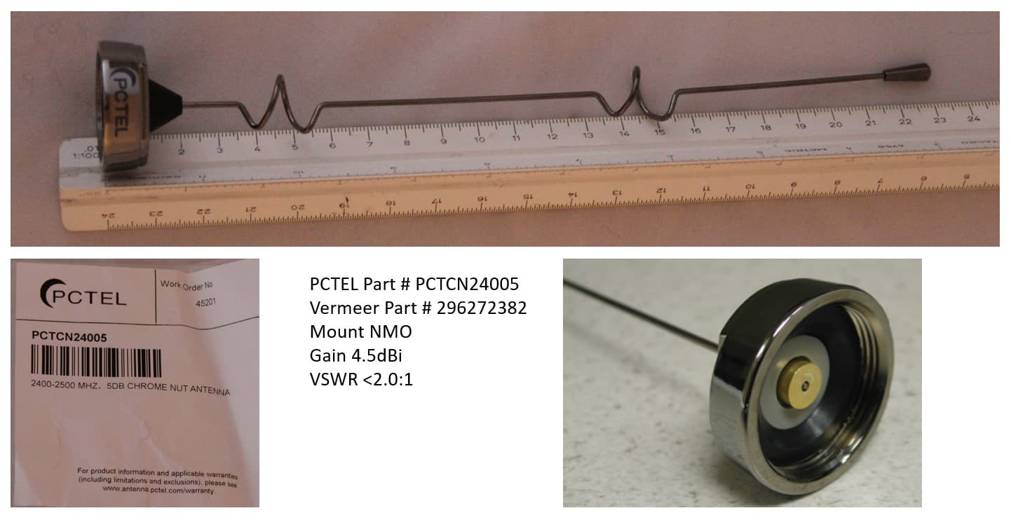
2AXF5-VERMEER2
Aug 30, 20222.4 GHz Radio Module
Equipment Class
DSS - Part 15 Spread Spectrum Transmitter