2AXF5-VERMEER22.4 GHz Radio Module
Vermeer Manufacturing Company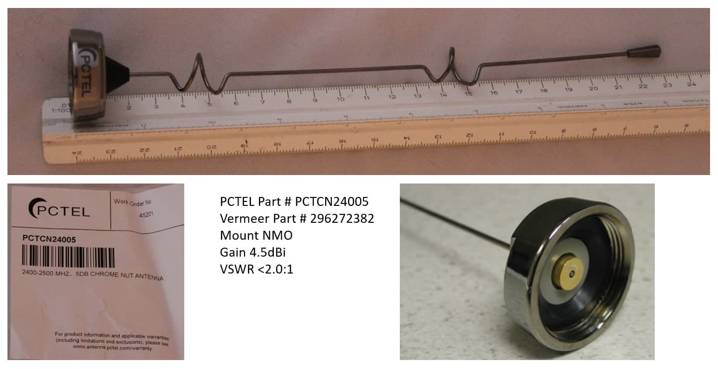
Click to zoom
Application Details
- Equipment Class
- DSS - Part 15 Spread Spectrum Transmitter
- Date of Grant
- Aug 30, 2022
- Application Purpose
- Original Equipment
- Date of Application
- Aug 14, 2022
- Equipment Note
- 2.4 GHz Radio Module
- Frequency Range
- 2404.00000000 - 2466.90000000
- Country
- United States
Documents & Files
Document Text
Text extracted from the exhibit documents filed with the FCC. Open a document above to read the original.
Users Manual
Regulatory Information FCC/IC Requirements for Modular Approval Agency Identification Numbers Product Family US/FCC (15.247) Canada/IC (RSS- 247) VERMEER2 2AXF5-VERMEER2 26431-VERMEER2 RADIO APPARATUS Family Laird Part # Vermeer Part # Form Factor RM024-S125-M-XX 312000365 Surface Mount RM024-P125-M-XX 312000381 Pluggable Antenna Information The RADIO APPARATUS family is designed to operate with the antennas listed below and a maximum gain of 9 dBi. The required antenna impedance is 50 ohms. Vermeer part # Manufacturer MFG Part # Type / Description Gain (dBi) 296575415 L-COM HG2409Y-NF Yagi 9.0 296575413 L-COM HG2409P-NF Flat Patch 8.0 296575414 L-COM HG2408P-NF Round Patch 8.0 296541293 Pulse / Larsen SLPT2400NMOHF Shadow 5.1 296575379 Nearson S151TC-2450 Dipole 5.0 296541296 Pulse / Larsen SLPT2400DMN Shadow 4.8 163722969 Laird TRA6927M3PB-001 Phantom 4.6 296272382 PCTEL PCTCN24005 Open Coil Colinear 4.5 296541297 Laird Connectivity TRAB24003P Phantom 3.0 296541408 Molex 146153 100mm Balance Flex 3.0 296589356 Laird Connectivity TRAB24003NP Phantom 3.0 296304935 Pulse / Larsen SPDA172400 Dipole 2.0 296521447 Laird Technologies MAF94045 PCB Trace 2.0 296541344 Nearson S181FL-5(178)-PX-2450 Dipole 2.0 296541409 Molex 146153 150mm Balance Flex 2.0 296575378 Nearson S181TC-2450 Dipole 2.0 296575416 Nearson S181FL-6-PX-2450S Dipole 2.0 296575417 Laird Technologies 001-0014 FlexPIFA 2.0 • To reduce potential radio interference to other users, the antenna type and gain should be chosen so that the equivalent isotropically radiated power (EIRP) is not more than that permitted for successful communication. • The OEM is free to choose another vendor’s antenna of like type and equal or lesser gain as an antenna appearing in the table and still maintain compliance. Reference FCC Part 15.204(c)(4) for further information on this topic. Power Exposure Information FCC In general, there are two agency classifications for RF radiation exposure in wireless applications: ▪ Mobile – A mobile device is defined as a transmitting device designed to be used in such a way that a separation distance of at least 20 centimeters is normally maintained between the transmitter's radiating structures and the body of the user or nearby persons. The RADIO APPARATUS is fully modular approved for mobile and fixed applications. Reference FCC Part 2.1091 for further details on mobile devices. ▪ Portable – Portable is a classification of equipment where the user, in general, is within 20 cm of the transmitting antenna. Further RF evaluation is required by customers who want to use the RADIO APPARATUS in portable applications that do not meet the minimum separation distance required for RF Exposure compliance referenced in the note below.. Contact a qualified test house or a Vermeer Corporation representative for further information on this topic. Reference FCC Part 2.1093 for further details on portable devices. A RF Exposure report has been created to demonstrate compliance with the SAR Test Exclusion Threshold (for the FCC) and with the Exemption Limit for Routine SAR Evaluation (for ISED), provided the minimum separation distances are maintained. Note: To comply with FCC RF Exposure requirements, a minimum separation distance of 9 cm must be maintained: CAUTION: Any changes or modifications not expressly approved by Vermeer Corporation could void the user’s authority to operate the equipment. NOTE: This equipment has been tested and found to comply with the limits for a Class B digital device, pursuant to Part 15 of the FCC Rules. These limits are designed to provide reasonable protection against harmful interference in a residential installation. This equipment generates, uses, and can radiate radio frequency energy and, if not installed and used in accordance with the instructions, may cause harmful interference to radio communications. However, there is no guarantee that interference will not occur in a particular installation. If this equipment does not cause harmful interference to radio or television reception, which can be determined by turning the equipment off and on, the user is encouraged to correct the interference by one or more of the following measures: ▪ Re-orient or relocate the receiving antenna. ▪ Increase the separation between the equipment and the receiver. ▪ Connect the equipment to an outlet on a circuit that is different from that to which the receiver is connected. ▪ Consult the dealer or an experienced radio/TV technician for help. CAUTION: “THIS DEVICE COMPLIES WITH PART 15 OF THE FCC RULES AND INDUSTRY CANADA LICENSE-EXEMPT RSS STANDARD(S). OPERATION IS SUBJECT TO THE FOLLOWING TWO CONDITIONS: (1) THIS DEVICE MAY NOT CAUSE HARMFUL INTERFERENCE, AND (2) THIS DEVICE MUST ACCEPT ANY INTERFERENCE RECEIVED, INCLUDING INTERFERENCE THAT MAY CAUSE UNDESIRED OPERATION.” Information on test modes and additional testing requirements Additional guidance for testing host products is given in KDB Publication 996369 D04 Module Integration Guide. Test modes should take into consideration different operational conditions for a stand-alone modular transmitter in a host, as well as for multiple simultaneously transmitting modules or other transmitters in a host product. Additional testing – Part 15 Subpart B disclaimer The module is only FCC authorized for the specific rule parts listed on the grant, and that the host product must be compliant to any other FCC rules that apply to the host not covered by the modular transmitter grant of certification. The final host product still requires Part 15 Subpart B compliance testing with the modular transmitter installed. Industry Canada Statement This device contains license-exempt transmitter(s)/receiver(s) that comply with Innovation, Science and Economic Development Canada’s license-exempt RSS(s). Operation is subject to the following two conditions: (1) This device may not cause interference (2) This device must accept any interference, including interference that …
Text truncated - open the document above for the full version.
Cover Letter(s)
Request for Confidentiality Date: June 25, 2022 Subject: Confidentiality Request for: FCC ID: 2AXF5-VERMEER2 & IC: 26431-VERMEER2 Pursuant to FCC 47 CFR 0.457(d) a nd 0.459 and IC RSP-100, Section 12.4, the applicant requests that a part of the subject FCC application be held confidential. Type of Confidentiality Requested Exhibit ☐ Short Term☒Permanent Block Di agrams ☐Short TermExternal Pho tos ☐Short Term☐Permanent * 1 Internal Photos ☐Short Term☒PermanentOperation Description/Theory of Operation ☐Short Te rm☒PermanentSchematics ☐Short Te rmTest Setup Photos ☐Short Te rm☐Permanent * 3 User’s Manual Vermeer Manufacturing Company has spent substantial effort in developing this product and it is one of the first of its kind in industry. Having the subject information easily available to "competition" would negate the advantage they have achieved by developing this product. Not protecting the details of the design will result in financial hardship. Permanent Confidentiality: The applicant requests the exhibits listed above as permanently confidential be permanently withheld from public review due to materials that contain trade secrets and proprietary information not customarily released to the public. Short-Term Confidentiality: The applicant requests the exhibits selected above as short term confidential be withheld from public view for a period of 180 days from the date of the Grant of Equipment Authorization and prior to marketing. This is to avoid premature release of sensitive information prior to marketing or release of the product to the public. Applicant is also aware that they are responsible to notify ACB in the event information regarding the product or the product is made available to the public before the requested period has expired. ACB will then release the documents listed above for public disclosure pursuant to FCC Public Notice DA 04-1705. 1 - The asterisked items (*) require further information to be provided to ACB before permanent confidentiality will be extended to these exhibits. Please refer to FCC KDB 726920 and the specific Document link for D01 found at: https://apps.fcc.gov/oetcf/kdb/forms/FTSSearchResultPage.cfm?switch=P&id=41731 and review section II, 3) regarding specific information that must accompany these requests.
External Photos
EXTERNAL PHOTOS Company Name Vermeer Manufacturing Company HVIN # VERMEER2 FCC ID # 2AXF5-VERMEER2 IC # 26431-VERMEER2 Page 1 of 3 Surface Mount (312000365) EXTERNAL PHOTOS Company Name Vermeer Manufacturing Company HVIN # VERMEER2 FCC ID # 2AXF5-VERMEER2 IC # 26431-VERMEER2 Page 2 of 3 Pluggable Through Hole (312000381) EXTERNAL PHOTOS Company Name Vermeer Manufacturing Company HVIN # VERMEER2 FCC ID # 2AXF5-VERMEER2 IC # 26431-VERMEER2 Page 3 of 3 Top side pluggable adapter stand Bottom side adapter stand Side view
ID Label/Location Info
INTERPRET TO ASME Y14.5 - 2009 X. XXX DESCRIPTION ITEM NUMBER DESIGN BY UNLESS OTHERWISE SPECIFIED CONTENTS ARE THE PROPERTY OF DIMENSIONS ARE IN INCHES DATE CHANGE X. XX X. X WRITTEN PERMISSIONS FROM OF VERMEER CORPORATION. NOTICE: THIS DOCUMENT AND ITS FRAC.DIM. SURFACE FINISH VERMEER CORPORATION OR ITS U.S. STANDARD TOLERANCES AFFILIATED COMPANIES. NO USE OR WPS 3 - 3 - A-100 BY DATE SUB. MATL SPECS 296541746 DZ 2020-10-13 279022 RELEASED TO PRODUCTION DZ B A 281425 ADDED MISSING MODEL NUMBER AND CERTIFICATION DZ 2022-02-22 1 1 DO NOT SCALE DRAWING DECAL, CERTIFICATION, MODULE 312000365 296541746 REV A ECN CHANGE DESCRIPTION 2021-08-05 Approximate Weight = 0.00 lbs NUMBERS COPIES MAY BE MADE WITHOUT PAGE 3RD ANGLE PROJECTION ANGLES ± .060± .030± .010± 1/32± 1 125 ITEM NO. PART NUMBER DESCRIPTION QTY. 1 296541547 LABEL BLANK, RM024 CERTIFICATION 1 1. COLOR: BLACK PRINT ON WHITE LABEL2. FINISH: GLOSS3. MUST BE ROHS COMPLIANT4. SELF-ADHESIVE WITH BACKING DATE CODE: 2 DIGIT YEAR/2 DIGIT WEEK 5. 5. RADIO APPARATUSModel: VERMEER2P/N: 312000365 (SMT)FCC ID: 2AXF5-VERMEER2IC: 26431-VERMEER2YY/WW .63 .63 X. XXX DESCRIPTION ITEM NUMBER DESIGN BY DATE ANGLESSURFACE FINISH FRAC.DIM. NOTICE: THIS DOCUMENT AND ITS X. X X. XX VERMEER CORPORATION. WRITTEN PERMISSIONS FROM OF 3RD ANGLE PROJECTION PAGE COPIES MAY BE MADE WITHOUT AFFILIATED COMPANIES. NO USE OR VERMEER CORPORATION OR ITS U.S. STANDARD TOLERANCES ECN WPS 3 - 3 - A-100 BY DATE SUB. MATL SPECS 296575397 DZ 2022-02-22 281425 RELEASED TO PRODUCTION DZ A 1 1 DO NOT SCALE DRAWING DECAL, CERTIFICATION, MODULE 312000381 296575397 REV A CHANGE DESCRIPTION 2022-02-22 Approximate Weight = 0.00 lbs CHANGE INTERPRET TO ASME Y14.5 - 2009 DIMENSIONS ARE IN INCHES UNLESS OTHERWISE SPECIFIED CONTENTS ARE THE PROPERTY OF ± .060± .030± .010± 1/32± 1 125 ITEM NO. PART NUMBER DESCRIPTION QTY. 1 296541547 LABEL BLANK, RM024 CERTIFICATION 1 1. COLOR: BLACK PRINT ON WHITE LABEL2. FINISH: GLOSS3. MUST BE ROHS COMPLIANT4. SELF-ADHESIVE WITH BACKING DATE CODE: 2 DIGIT YEAR/2 DIGIT WEEK 5. 5. RADIO APPARATUSModel: VERMEER2P/N: 312000381 (PTH)FCC ID: 2AXF5-VERMEER2IC: 26431-VERMEER2YY/WW .63 .63 Pluggable Through Hole Label Placement Surface Mount Label Placement
Internal Photos
INTERNAL PHOTOS Company Name Vermeer Manufacturing Company HVIN # VERMEER2 FCC ID # 2AXF5-VERMEER2 IC # 26431-VERMEER2 Page 1 of 2 Pluggable Through Hole (312000381) INTERNAL PHOTOS Company Name Vermeer Manufacturing Company HVIN # VERMEER2 FCC ID # 2AXF5-VERMEER2 IC # 26431-VERMEER2 Page 2 of 2 Surface Mount (312000365)
RF Exposure Info
A Company: Vermeer Manufacturing Company Page 1 of 17 Name: RADAIO APPARATUS Report: 3538 B Model: VERMEER2 Quote: NBO-10-2021-004287 Serial: Engineering Sample Test Report # 3538 B Equipment Under Test: RADIO APPARATUS Requirements: FCC Part 1.1307, 2.1091, 2.1093 | ISED Canada RSS-102 Test Date(s): November 22-24 and December 20, 2021 Prepared for: Vermeer Manufacturing Company Attn: Ty Gross 1716 Vermeer Rd East Pella, IA 50219 Report Issued by: Adam Alger, Laboratory Manager Signature: Date: 8/30/2022 Report Reviewed by: Zach Wilson, EMC Engineer Signature: Date: 3/15/2022 Report Constructed by: Adam Alger, Laboratory Manager Signature: Date: 3/04/2022 This test report may not be reproduced, except in full, without approval of Laird Connectivity LLC Company: Vermeer Manufacturing Company Page 2 of 17 Name: RADIO APPARATUS Report: 3538 B Model: VERMEER2 Quote: NBO-10-2021-004287 Serial: Engineering Sample CONTENTS Contents ........................................................................................................................................................ 2 Laird Connectivity Test Services in Review ............................................................................................... 3 1 Test Report Summary ........................................................................................................................... 4 2 Client Information ................................................................................................................................. 5 2.1 Equipment Under Test (EUT) Information .................................................................................... 5 2.2 Product Description ...................................................................................................................... 5 2.3 Modifications Incorporated for Compliance ................................................................................. 5 2.4 Deviations and Exclusions from Test Specifications ..................................................................... 5 2.5 Additional Information .................................................................................................................. 5 2.6 Antenna Information .................................................................................................................... 6 3 References ............................................................................................................................................ 7 4 Uncertainty Summary ........................................................................................................................... 8 5 Test Data ............................................................................................................................................... 9 5.1 Antenna Port Conducted Emissions .............................................................................................. 9 5.2 FCC RF Exposure Calculations ..................................................................................................... 13 5.3 ISED RF Exposure Calculations .................................................................................................... 15 6 Revision History .................................................................................................................................. 17 Company: Vermeer Manufacturing Company Page 3 of 17 Name: RADIO APPARATUS Report: 3538 B Model: VERMEER2 Quote: NBO-10-2021-004287 Serial: Engineering Sample Laird Connectivity Test Services in Review The Laird Connectivity LLC laboratory located at W66 N220 Commerce Court Cedarburg, Wisconsin, 53012 USA is recognized through the following organizations: A2LA – American Association for Laboratory Accreditation Accreditation based on ISO/IEC 17025:2017 with Electrical (EMC) Scope A2LA Certificate Number: 1255.01 Scope of accreditation includes all test methods listed herein unless otherwise noted Federal Communications Commission (FCC) – USA Accredited Test Firm Registration Number: 953492 Recognition of two 3 meter Semi-Anechoic Chambers Innovation, Science and Economic Development Canada Accredited U.S. Identification Number: US0218 Recognition of two 3 meter Semi-Anechoic Chambers Company: Vermeer Manufacturing Company Page 4 of 17 Name: RADIO APPARATUS Report: 3538 B Model: VERMEER2 Quote: NBO-10-2021-004287 Serial: Engineering Sample 1 TEST REPORT SUMMARY During November 22-24 and December 20, 2021 the Equipment Under Test (EUT), RADIO APPARATUS, as provided by Vermeer Manufacturing Company was tested to the following requirements: Requirement Description Specification Method Result FCC Part 1.1307, 2.1091, 2.1093 RF Exposure and equipment authorization requirements Reported FCC KDB 447498 Reported ISED Canada RSS-102 Radiofrequency Radiation Exposure Evaluation: Portable Reported RSS-102 Section 2.5.2 Reported Notice: The results relate only to the item tested as configured and described in this report. Any additional configurations, modes of operation, or modifications made to the equipment under test after the specified test date(s) are at the decision of the client and may not apply to the data seen in this test report. The decision rule for Pass / Fail assessment to the specification or standard listed in this test report has been agreed upon by the client and laboratory to be as follows: Measurement Type Rule Emissions – Amplitude Below specified limit Emissions – Frequency 1% less than the specification Immunity Tested at specified level Company: Vermeer Manufacturing Company Page 5 of 17 Name: RADIO APPARATUS Report: 3538 B Model: VERMEER2 Quote: NBO-10-2021-004287 Serial: Engineering Sample 2 CLIENT INFORMATION Company Name Vermeer Manufacturing Company Contact Person Ty Gross Address 1716 Vermeer Rd East Pella, IA 50219 2.1 Equipment Under Test (EUT) Information The following information has been supplied by the client Product Name RADIO APPARATUS Model Numbe…
Text truncated - open the document above for the full version.
Test Report
A Company: Vermeer Manufacturing Company Page 1 of 44 Name: RADIO APPARATUS Report: 3538 A Model: VERMEER2 Quote: NBO-10-2021-004287 Serial: Engineering Sample Test Report # 3538 A Equipment Under Test: Radio Apparatus Test Date(s): November 22-24 and December 20, 2021 Prepared for: Vermeer Manufacturing Company Attn: Ty Gross 1716 Vermeer Rd East Pella, IA 50219 Report Issued by: Adam Alger, Laboratory Manager Signature: Date: 8/8/2022 Report Reviewed by: Zach Wilson, EMC Engineer Signature: Date: 12/21/2021 Report Constructed by: Adam Alger, Laboratory Manager Signature: Date: 12/01/2021 This test report may not be reproduced, except in full, without approval of Laird Connectivity LLC Company: Vermeer Manufacturing Company Page 2 of 44 Name: RADIO APPARATUS Report: 3538 A Model: VERMEER2 Quote: NBO-10-2021-004287 Serial: Engineering Sample CONTENTS Contents ........................................................................................................................................................ 2 Laird Connectivity Test Services in Review ............................................................................................... 3 1 Test Report Summary ........................................................................................................................... 4 2 Client Information ................................................................................................................................. 5 2.1 Equipment Under Test (EUT) Information .................................................................................... 5 2.2 Product Description ...................................................................................................................... 5 2.3 Modifications Incorporated for Compliance ................................................................................. 5 2.4 Deviations and Exclusions from Test Specifications ..................................................................... 5 2.5 Additional Information .................................................................................................................. 5 2.6 Antenna Information .................................................................................................................... 6 2.7 Cabinet Radiation Method ............................................................................................................ 6 3 References ............................................................................................................................................ 7 4 Uncertainty Summary ........................................................................................................................... 8 5 Test Data ............................................................................................................................................... 9 5.1 Antenna Port Conducted Emissions .............................................................................................. 9 5.2 Radiated Emissions ..................................................................................................................... 33 5.3 AC Mains Conducted Emissions .................................................................................................. 41 6 Revision History .................................................................................................................................. 44 Company: Vermeer Manufacturing Company Page 3 of 44 Name: RADIO APPARATUS Report: 3538 A Model: VERMEER2 Quote: NBO-10-2021-004287 Serial: Engineering Sample Laird Connectivity Test Services in Review The Laird Connectivity LLC laboratory located at W66 N220 Commerce Court Cedarburg, Wisconsin, 53012 USA is recognized through the following organizations: A2LA – American Association for Laboratory Accreditation Accreditation based on ISO/IEC 17025:2017 with Electrical (EMC) Scope A2LA Certificate Number: 1255.01 Scope of accreditation includes all test methods listed herein unless otherwise noted Federal Communications Commission (FCC) – USA Accredited Test Firm Registration Number: 953492 Recognition of two 3 meter Semi-Anechoic Chambers Innovation, Science and Economic Development Canada Accredited U.S. Identification Number: US0218 Recognition of two 3 meter Semi-Anechoic Chambers Company: Vermeer Manufacturing Company Page 4 of 44 Name: RADIO APPARATUS Report: 3538 A Model: VERMEER2 Quote: NBO-10-2021-004287 Serial: Engineering Sample 1 TEST REPORT SUMMARY During November 22-24 and December 20, 2021 the Equipment Under Test (EUT), RADIO APPARATUS, as provided by Vermeer Manufacturing Company was tested to the following requirements: Requirement Description Specification Method Result FCC: 15.247 (a)(1) IC: RSS-247 5.1 Channel Separation, Number of Hopping frequencies, Time of Occupancy FHSS ANSI C63.10 Compliant FCC: 2.1049 IC: RSS-GEN 6.7 Occupied Bandwidth Reported ANSI C63.10 Reported FCC: 15.247 (b)(1) IC: RSS-247 5.4 (b) Maximum Conducted Output Power 21 dBm ANSI C63.10 Compliant FCC: 15.247 (d) IC: RSS-247 5.5 RF Spurious Emissions at the Transmitter Antenna Terminal 20 dBc ANSI C63.10 Compliant FCC: 15.247 (d) IC: RSS-GEN 8.10 Spurious Radiated Emissions in Restricted Bands FCC 15.209 RSS-GEN 8.9 ANSI C63.10 Compliant FCC: 2.1055 (d) IC: RSS-GEN 6.11 Frequency Stability Reported ANSI C63.10 Compliant FCC: 15.207 IC: RSS-GEN 8.8 Conducted AC Mains Emissions Class B ANSI C63.10 Compliant Notice: The results relate only to the item tested as configured and described in this report. Any additional configurations, modes of operation, or modifications made to the equipment under test after the specified test date(s) are at the decision of the client and may not apply to the data seen in this test report. The decision rule for Pass / Fail assessment to the specification or standard listed in this test report has been agreed upon by the client and laboratory to be as follows: Measurement Type Rule…
Text truncated - open the document above for the full version.
Test Report
Laird Connectivity 50 South Main Street, Ste 1100 Akron, OH, 44311, USA Americas: +1-262-375-4400 Europe: +44-1628-858-940 www.lairdconnect.com Informational Notice FAO - Jon Stanford, Sr. Project Engineer – Embedded Hardware Vermeer Corporation, Advanced Technology Solutions 1716 Vermeer Road East Pella, IA 50219 The former Laird Connectivity part # 0600-00040 is identical in form, fit and function to the Nearson part # S181FL-6-PX-2450S that is certified with Laird Connectivty’s RM024 module series. Signed: Name: Jonathan Kaye Position: VP - Product Management Date: 20 th April 2022
Test Report
This document was generated on 07/20/2020 PLEASE CHECK WWW.MOLEX.COM FOR LATEST PART INFORMATION Part Number: 1461530100 Status: Active Overview:Internet of Things (IoT) Antennas: Wi-Fi, Bluetooth, Zigbee Description:2.4GHz / 5GHz Wi-Fi Stand Alone Balance Antenna, 9.00mm Width, 100.00mm Cable Length, Compatible with U.FL / I-PEX MHF Connectors Documents: 3D ModelApplication Specification AS-146153-100-001 (PDF) Drawing (PDF)Packaging Specification 1461530100-000 (PDF) 3D Model (PDF)Datasheet (PDF) Product Specification PS-146153-100-001 (PDF)RoHS Certificate of Compliance (PDF) General Product FamilyAntennas Series146153 Component TypeFlexible Antenna with Cable FunctionSignal Mates WithMolex Receptacle 734120110 and other alternatives OverviewInternet of Things (IoT) Antennas: Wi-Fi, Bluetooth, Zigbee Product Name2.4/5GHz Balanced Flex Antenna ProtocolBLE, BT, Thread, Wi-Fi, Wireless Hart, Zigbee TypeWi-Fi Antenna UPC889056310017 Physical Cable Length100.00mm Length34.90mm Mounting StyleAdhesive Net Weight0.574/g Packaging TypePET Film PolarizationLinear Radiation PatternOmnidirectional Thickness0.10mm Width9.00mm Electrical Band#1 F_End (MHz)2483.5 Band#1 F_Start (MHz)2400 Band#2 F_End (MHz)5930 Band#2 F_Start (MHz)4900 Electrical ConnectivityCable Peak Gain (dBi)3.0 @ 2.4 GHz, 4.0 @ 5 GHz Return Loss - S11 (dB)< -10 Total Efficiency>75% @ 2.4 GHz, >75% @ 5 GHz Material Info Reference - Drawing Numbers Application SpecificationAS-146153-100-001 Packaging Specification1461530100-000 Product SpecificationPS-146153-100-001 Sales DrawingSD-146153-050-001 Series image - Reference only EU ELV Not Relevant EU RoHSChina RoHS Compliant REACH SVHC Not Contained Per - D(2020)4578-DC (25 June 2020) Halogen-Free Status Low-Halogen For more information, please visit Contact US China ROHSGreen Image ELVNot Relevant RoHS PhthalatesNot Contained Search Parts in this Series 146153 Series This document was generated on 07/20/2020 PLEASE CHECK WWW.MOLEX.COM FOR LATEST PART INFORMATION
Test Report
A Operating Frequency (MHz) 2400-2500 VSWR ≤2.0 Gain (dBi) 2.0 Radiation Omnidirectional Nominal Impedance (Ohms) 50 Polarization Vertical Radome Material Polyurethane (black) Cable Ø1.37 Connector I-PEX/MHF1 Operating Temperature – °C (°F) -20 to +65 (-4 to +149) [email protected] [email protected] www.lairdconnect.com Laird Connectivity warrants to the original end user customer of its products that its products are free from defects in material and workmanship. Subject to conditions and limitations Laird Connectivity will, at its option, either repair or replace any part of its products that prove defective because of improper workmanship or materials. This limited warranty is in force for the useful lifetime of the original end product into which the Laird Connectivity product is installed. Useful lifetime of the original end product may vary but is not to exceed five (5) years from the original date of the end product purchase. Any information furnished by Laird Connectivity and its agents is believed to be accurate and reliable. All specifications are subject to change without notice. Responsibility for the use and application of Laird Connectivity materials rests with the end user, since Laird Connectivity and its agents cannot be aware of all potential uses. Laird Connectivity makes no warranties as to the fitness, merchantability. or suitability of any Laird Connectivity materials or products for any specific or general uses. Laird Connectivity shall not be liable for incidental or consequential damages of any kind. All Laird Connectivity products are sold pursuant to the Laird Connectivity Terms and Conditions of sale in effect from time to time, a copy of which will be furnished upon request. © Copyright 2020 Laird Connectivity Inc. All Rights Reserved. Laird Connectivity, the Laird Connectivity logo, and other marks are trademarks or registered trademarks of Laird Connectivity or an affiliate company thereof. Other product or service names may be the property of third parties. Nothing herein provides a license under any Laird Connectivity or any third party intellectual property rights.
Test Report
A The evolution of technology has brought the need to communicate everywhere and at all times without being confined to one space. Laird Technologies’ internal wireless device antennas feature wide bandwidth to enhance the performance and application of portable wireless devices based on standards such as 802.11 and Bluetooth®. The antennas are specifically designed to be embedded inside devices for aesthetically pleasing integration with high durability. ▪ Versatile, easy-to-use for 2.4 to 2.5 GHz Bluetooth® and IEEE 802.11 devices ▪ Designed for an easy connection to radio cards ▪ Uses patented PCB Microsphere technology ▪ Has a ground plane incorporated into the resonator structure – no additional ground plane is required to radiate efficiently Operating Frequency (MHz) 2.4 – 2.5 GHz VSWR – Max <2.5:1 Gain (dBi) 2 Nominal Impedance (Ohms) 50 Polarization Linear Dimensions 44.45 mm (1.75 in.) x 12.7 mm (0.5 in.) x 0.81 mm (0.032 in.) Weight 2 g (0.071 oz.) MAF94045 100 mm, Ø 1.13 mm IPEX MHF MAF94102 100 mm, RG178 Flying Lead EBL2400A1-10MH4L 100 mm MHF4 [email protected] [email protected] www.lairdconnect.com Laird warrants to the original end user customer of its products that its products are free from defects in material and workmanship. Subject to conditions and limitations Laird will, at its option, either repair or replace any part of its products that prove defective because of improper workmanship or materials. This limited warranty is in force for the useful lifetime of the original end product into which the Laird product is installed. Useful lifetime of the original end product may vary but is not to exceed five (5) years from the original date of the end product purchase. Any information furnished by Laird Inc. and its agents is believed to be accurate and reliable. All specifications are subject to change without notice. Responsibility for the…
Text truncated - open the document above for the full version.
Contact Information
Applicant
Daniel W Huitink(Deputy General Counsel)
Technical Contact
Test Firm
EzurioAdam Alger
Technical Specifications
| # | Rule Parts | Frequency Range | Power Output |
|---|---|---|---|
| 1 | 15C | 2.40 GHz - 2.47 GHz | 91.20 mW |
Other Applications from Vermeer Manufacturing Company
2AXF5-VTSSEN1
May 29, 2023Digital Transmission System
Equipment Class
DTS - Digital Transmission System
2AXF5-VERMEER1
Feb 22, 20212.4 GHz FHSS Wireless Module
Equipment Class
DSS - Part 15 Spread Spectrum Transmitter