2AXJ4AP9778BE22000 Ceiling Mount Wi-Fi 7 Access Point
TP-Link Corporation Limited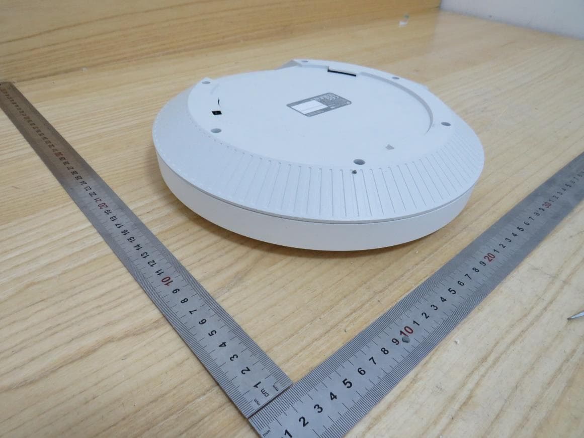
Click to zoom
Application Details
- Equipment Class
- DTS - Digital Transmission System
- Date of Grant
- Oct 02, 2023
- Application Purpose
- Original Equipment
- Date of Application
- Sep 09, 2023
- Equipment Note
- BE22000 Ceiling Mount Wi-Fi 7 Access Point
- Frequency Range
- 2412.00000000 - 2462.00000000
- Company
- TP-Link Corporation Limited
- Country
- Hong Kong
Documents & Files
Document Text
Text extracted from the exhibit documents filed with the FCC. Open a document above to read the original.
Users Manual
Regulatory Compliance Ceiling Mount AP FCC Compliance Information Statement Product Name: Omada Pro Ceiling Mount Access Point Model Number: AP9635 / AP9650 / AP9670 / AP9778 Responsible party: TP-Link USA Corporation Address: 10 Mauchly, Irvine, CA 92618 Website: https://www.tp-link.com/us/ Tel: +1 626 333 0234 Fax: +1 909 527 6804 E-mail: [email protected] This equipment has been tested and found to comply with the limits for a Class B digital device, pursuant to part 15 of the FCC Rules. These limits are designed to provide reasonable protection against harmful interference in a residential installation. This equipment generates, uses and can radiate radio frequency energy and, if not installed and used in accordance with the instructions, may cause harmful interference to radio communications. However, there is no guarantee that interference will not occur in a particular installation. If this equipment does cause harmful interference to radio or television reception, which can be determined by turning the equipment off and on, the user is encouraged to try to correct the interference by one or more of the following measures: •Reorient or relocate the receiving antenna. •Increase the separation between the equipment and receiver. •Connect the equipment into an outlet on a circuit different from that to which the receiver is connected. •Consult the dealer or an experienced radio/ TV technician for help. This device complies with part 15 of the FCC Rules. Operation is subject to the following two conditions: 1) This device may not cause harmful interference. 2) This device must accept any interference received, including interference that may cause undesired operation. Any changes or modifications not expressly approved by the party responsible for compliance could void the user’s authority to operate the equipment. Note: The manufacturer is not responsible for any radio or TV interference caused by unauthorized modifications to this equipment. Such modifications could void the user’s authority to operate the equipment. FCC RF Radiation Exposure Statement: This equipment complies with FCC RF radiation exposure limits set fo rth for an uncontrolled environment. This device and its antenna must not be co-located or operating in conjunction with any other antenna or transmitter. “To comply with FCC RF exposure compliance requirements, this grant is applicable to only Mobile Configurations. The antennas used for this transmitter must be installed to provide a separation distance of at least 20cm from all persons and must not be colocated or operating in conjunction with any other antenna or transmitter.” For AP9778: FCC regulations restrict operation of this device to indoor use only. The operation of this device is prohibited on oil platforms, cars, trains, boats, and aircraft, except that operation of this device is permitted in large aircraft while flying above 10000 feet in the 5.925-6.425 GHz band. Operation of transmitters in the 5.925-7.1 25 GHz band is prohibited for control of or communications with unmanned aircraft systems. We, TP-Link USA Corporation, has determined that the equipment shown as above has been shown to comply with the applicable technical standards, FCC part 15. There is no unauthorized c hange is made in the equipment and the equipment is properly maintained and operated. Issue Date: 2023-05-05 CE Mark Warning This is a class B product. In a domestic environment, this product may cause radio interference, in which case the user may be required to take adequate measures. OPERATING FREQUENCY (the maximum transmitted power) For AP9635 / AP9650 / AP9670: 2412 MHz -2472 MHz (20dBm) 5150 MHz -5250 MHz (23dBm) 5250 MHz -5350 MHz (23dBm) 5470 MHz -5725 MHz (30dBm) For AP9778: 2412 MHz -2472 MHz (20dBm) 5150 MHz -5250 MHz (23dBm) 5250 MHz -5350 MHz (23dBm) 5470 MHz -5725 MHz (30dBm) 5925MHz -6425 MHz (23dBm) EU Declaration of Conformity TP-Link hereby declares that the device is in compliance with the essential requirements and other relevant provisions of directives 2014/53/EU, 2009/125/EC, 2011/65/EU and (EU)2015/863. The original EU Declaration of Conformity may be found at https://www.tp-link.com/en/support/ce/. RF Exposure Information This device meets the EU requirements (2014/53/EU Article 3.1a) on the limitation of exposure of the general public to electromagnetic fields by way of health protection. The device complies with RF specifications when the device used at 20cm from your body. National Restrictions For AP9635 / AP9650 / AP9670: Frequency band: 5150 - 5250 MHz: Indoor use: Inside buildings only. Installations and use inside road vehicles and train carriages are not permitted. Limited outdoor use: If used outdoors, equipment shall not be attached to a fixed installation or to the external body of road vehicles, a fixed infrastructure or a fixed outdoor antenna. Use by unmanned aircraft systems (UAS) is limited to within the 5170 - 5250 MHz band. Frequency band: 5250 - 5350 MHz: Indoor use: Inside buildings only. Installations and use in road vehicles, trains and aircraft are not permitted. Outdoor use is not permitted. Frequency band: 5470 - 5725 MHz: Installations and use in road vehicles, trains and aircraft and use for unmanned aircraft systems (UAS) are not permitted. For AP9778: Frequency band: 5150 - 5250 MHz: Indoor use: Inside buildings only. Installations and use inside road vehicles and train carriages are not permitted. Limited outdoor use: If used outdoors, equipment shall not be attached to a fixed installation or to the external body of road vehicles, a fixed infrastructure or a fixed outdoor antenna. Use by unmanned aircraft systems (UAS) is limited to within the 5170 - 5250 MHz band. Frequency band: 5250 - 5350 MHz: Indoor use: Inside buildings only. Installations and use in road vehicles, trains and aircraft are not permitted. Outdoor use is not permitted. Frequency band: 5470 - 5725 MHz: Installations and use in road vehicles, trains …
Text truncated - open the document above for the full version.
Attestation Statements
Attestation Letter Federal Communications Commission Authorization and Evaluation Division We Name: TP-Link Corporation Limited Address: Room 901, 9/F., New East Ocean Centre, 9 Science Museum Road, Tsim Sha Tsui, Kowloon, Hongkong Declare that the device does not support channel 12 ~ 13 in 2.4GHz band, any non-US channels in all the operational mode(s) for the following product. Product: BE22000 Ceiling Mount Wi-Fi 7 Access Point FCC ID: 2AXJ4AP9778 Model: AP9778 Brand: tp-link Sincerely, Name: Sarah Wang Position: Regulatory Compliance Manager Date: 2023-8-20
Attestation Statements
012423-17 rev2 TP-Link Corporation Limited Certification Application Attestation Statements Date: March 1, 2023 American Certification Body, Inc. 313 Park Avenue Suite 300 Falls Church, VA 22046 T o Whom It May Concern: Statement for 47 CFR section 2.911(d)(5)(i) ______ TP-Link Corporation Limited______ certifies that as of the date of the application the equipment for which authorization is sought is not “covered” equipment 1 prohibited from receiving an equipment authorization pursuant to section 2.903 of the FCC rules. If the equipment for which the applicant seeks authorization is produced by any of the entities identified on the current Covered List, including affiliates or subsidiaries of the named companies, the applicant must include an explanation on why the equipment is not “covered” equipment. Additional Explanation: <N/A> Statement for 47 CFR section 2.911(d)(5)(ii) ______ TP-Link Corporation Limited______ (“the applicant”) certifies that, as of the date of the filing of this application, the applicant ☐ - is / ■- is not identified on the Covered List as an entity producing “covered” equipment. Thank you, By: _________________________ Sarah Wang (Signature 2 ) (Print name) Title: __ Regulatory Compliance Manager __ Company: __ TP-Link Corporation Limited_ Telephone: ___ 00852-37585053 ______ 1 - The Commission’s Covered List is published by the Public Safety and Homeland Security Bureau and posted on the Commission’s website. This Covered List, which is periodically updated, identifies particular equipment, produced by particular entities, that constitutes “covered” equipment. https://www.fcc.gov/supplychain/coveredlist . 2 - Letters should be placed on appropriate letterhead.
Cover Letter(s)
TP-Link Corporation Limited. 050222-17 Request for Confidentiality Date: August 22, 2023 Subject: Confidentiality Request for: ___ 2AXJ4AP9778 _____ Pursuant to FCC 47 CFR 0.457(d) and 0.459 and/or IC RSP-100, Section 12.4, the applicant requests that a part of the subject application(s) be held confidential. Type of Confidentiality Requested Exhibit ☐ Short Term ☒ Permanent Block Diagrams ☐ Short Term --------------------------- External Photos ☐ Short Term ☐ Permanent * 1 Internal Photos ☐ Short Term ☒ Permanent Operation Description/Theory of Operation ☐ Short Term ☐ Permanent Parts List & Placement/BOM ☐ Short Term ☐ Permanent Tune-Up Procedure ☐ Short Term ☒ Permanent Schematics ☐ Short Term --------------------------- Test Setup Photos ☐ Short Term ☐ Permanent * 1 User’s Manual TP-Link Corporation Limited.has spent substantial effort in developing this product and it is one of the first of its kind in industry. Having the subject information easily available to "competition" would negate the advantage they have achieved by developing this product. Not protecting the details of the design will result in financial hardship. Permanent Confidentiality: The applicant requests the exhibits listed above as permanently confidential be permanently withheld from public review due to materials that contain trade secrets and proprietary information not customarily released to the public. Short-Term Confidentiality for FCC Applications: The applicant requests the exhibits selected above as short term confidential be withheld from public view for a period of __ (specify number of days not to exceed 180) 2 ___ days from the date of the Grant of Equipment Authorization and prior to marketing. This is to avoid premature release of sensitive information prior to marketing or release of the product to the public. Applicant is also aware that they are responsible to notify ACB in the event information regarding the product or the product is made available to the public before the requested period has expired. ACB will then release the documents listed above for public disclosure pursuant to FCC Public Notice DA 04-1705. Short Term Confidentiality for Industry Canada Applications: Starting May 2022, ISED will recognize short term confidentiality on certain exhibits until the intended date of marketing. The applicant requests the exhibits selected above as short term confidential be withheld from public view until: (specify ISED expiration date / date of marketing) . Sincerely, By: __________________________ __________ Sarah Wang ______________ (Signature/Title 3 ) (Print name) 1 - The asterisked items (*) require further information to be provided to ACB before permanent confidentiality will be extended to these exhibits. Please refer to FCC KDB 726920 and the specific Document link for D01 found at: https://apps.fcc.gov/oetcf/kdb/forms/FTSSearchResultPage.cfm?switch=P&id=41731 and review section II, 3) regarding specific information that must accompany these requests. 2 - Please refer to https://acbcert.com/documents/misc-docs/Memo-Short-Term-Vs-Standard-Confidentiality.pdf for complete details. 3 - Must be signed by applicant contact given for applicant on the FCC site, or by the authorized agent if an appropriate authorized agent letter has been provided. Letters should be placed on appropriate letterhead.
Cover Letter(s)
Declaration of Frequency Stability We [TP-Link Corporation Limited] ensure that the product (FCC ID: 2AXJ4AP9778) meets e- CFR Title 47 section 15.407(g) and KDB 789033 D02v02r01 frequency stability such that the emissions are maintained within the band of operation under all conditions of normal operation as specified in the user's manual. Sincerely, Name: Sarah Wang Position: Regulatory Compliance Manager Date: 2023-8-20
Cover Letter(s)
Declaration of Conformity We Name: TP-Link Corporation Limited Address: Room 901, 9/F., New East Ocean Centre, 9 Science Museum Road, Tsim Sha Tsui, Kowloon, Hongkong Declare that: Product: BE22000 Ceiling Mount Wi-Fi 7 Access Point FCC ID: 2AXJ4AP9778 Model: AP9778 Brand: tp-link Product which bears the above FCC ID is also compliant with the FCC requirements for sDOC. And the sDOC procedure shall be carried out prior to marketing the device in the US. Sincerely, Name: Sarah Wang Position: Regulatory Compliance Manager Date: 2023-8-20
Cover Letter(s)
Non-SDR (Software Defined Radio) Cover Letter Refer to KDB 442812 D01 SDR apps Guide v02r03. The following six questions can be used for determining if a radio can elect to be, or must be an SDR. 1. Can the RF parameters of the device be altered through software? Yes - go to 2. No, not an SDR No 2. Can third parties not permitted by the Commission through specific filings modify, configure, or load different software, or make configuration settings to operate the device or host hardware radio frequency parameters (frequency range, modulation type, maximum output power or other radio parameters) in any other way than granted (or expected to be granted)? Yes, must be an SDR. No - go to 3. No 3. Is the device capable of operating in any other in any other way than granted, or will be, granted? Yes, - go to 4. No - go to 5. No 4. Is this a Part 15 client Device as defined in Section 15.202 (as opposed to a master device)? Yes, qualifies as a part 15 client devices - go to 5. No, must be an SDR. 5. Does the manufacturer elect SDR? Yes, elects to be an SDR. No, Not an SDR No Conclusion: According to the above questions reply, we can confirm this device (FCC ID: 2AXJ4AP9778) must be a Non-SDR device. Name: Sarah Wang Position: Regulatory Compliance Manager Date: 2023-8-20
Cover Letter(s)
UN 6GHZ PRE-APPROVAL GUIDANCE CHECKLIST 1.Antennas 1.1 Info rmati on fo r all the an te nnas, i.e., ty pe, gain an d relati ve positio ns within host, mus t be included in the filing. Please refer to page 20 of “47 90887256-1-RF-4-WIFI 6G FCC ISED ” for antenna specification. Please refer to document “Internal Photos” for the antenna positions. 1.2 Show how the (aggregate, if applicabl e) antenna gain was computed/ measured (as in TCB Workshop Presentation Aggrega te Anten na Gain Review, April 2021). Provi de equation(s) used to calculate Directional Gain and provide example calculation showing how the DG was calculated with the antenna gain of individual antennas. Provi de details (references or attached documents) on how the indi vidua l antenna gains were derived, i.e., declared by the host manufacturer, based on data sheet, or measured. Since the CBP needs to detect a small signal, the worst case scenari o to consider is when the receiver has the lowest antenna gain. The device has the same maximum antenna gain for each anten na. According to FCC KDB 662911 D01v02r01: CDD Directional Gain = Antenna Gain + Array Gain, Array Gain = 0 dB for NANT ≤ 4; please refer to page 20 of “4790887256-1-RF-4-WIFI 6G FCC ISED” For output power measurements: Directional gain= GANT + Array Gain = 2 dBi GANT : equal to the gain of the antenna having the highest gain Array Gain = 0 dB (i.e., no array gain) for NANT ≤ 4 For power spectral density (PSD) measurements: Directional gain= GANT + Array Gain = 5.01 dBi Array Gain = 10 log(NANT/NSS) dB. NANT : number of transmit antennas NSS : number of spatial streams, The worst case directional gain will occur when NSS = 1 For TX Beamforming: Directional gain= GANT + 10 log(NANT/NSS) = 5.01 dBi 1.3 For conducted test in MIMO cases, show that the testing was done for that path that has the lowest antenna gain. The device has the same maximum antenna gain for each antenna. 2.Contention Based Protocol (CBP) 2.1 CBP testing sh all be perfo rmed on one channel in each sub-band of operati on fo r both narrowest and widest bandwidths. Please refer to page 469-470of “4790887256-1-RF-4-WIFI 6G FCC ISED” for the test channel and bandwidth information as follows. The narrowest and widest bandwidths were test for each UNII band. 2.2 Use three separate 10 MHz AWGN signals when testin g a 320 MHz channel. The simulated incumbent signal must be a 10 MHz wide AWGN signal Please refer to page 470 -472of “4790887256-1-RF-4-WIFI 6G FCC ISED” for the test summary information. Please refer to page 473~474of “4790887256-1-RF-4-WIFI 6G FCC ISED” for the AWGN signal plots. 2.3 Report lowest AWGN signal detectable by EUT Please refer to page 469-470 of “4790887256-1-RF-4-WIFI 6G FCC ISED” for lowest AWGN signal detectable by EUT. 2.4 Verify that the testing was performed with the A WGN signal set to lowest level (for example, - 100 dBm) an d increased until the EUT detects and stops transmitting. The test was perfo rmed with a lowest AW GN sig nal lev el an d in creas ed until the EUT de tects and stop tra ns mi ssion , an d th e AW GN lev el of AW GN sig nal detected (S top bu t with Beacon si gnal) and AWGN level of the stopped transmission are recorded in the report. Please refer to page 469-470 of “4790887256-1-RF-4-WIFI 6G FCC ISED” of RF report for the information. 2.5 If con ducted mea su remen ts ar e used , the detection threshol d needs to be co rrected to refe r to a 0 dB i gain an te nn a an d incl ud e all the applicable lo sses (cables, etc.) . For in stan ce, the repo rt shou ld sho w (at least): Detection Lev el = In jected AW GN Power (dB m) – Ante nna Gain (dB i) + Path Los s (dB) Conducted test is performed for this device. Please refer to page 39of “4790887256-1-RF-4-WIFI 6G FCC ISED" for the test setup diagram as below. Please refer to page 38 of “47 90887256-1-RF-4-WIFI 6G FCC ISED” for the relevant description. 2.6 Include plots showing EUT has stopped transmitting after detection of AWGN signal. Please refer to page 475-4 88 of “47 90887256-1-RF-4-WIFI 6G FCC ISED” for the test result. Following is example. 2.7 Describe whether channel puncturing and/or ban dwi dth re ducti on me chanisms s upp orte d. The report n eeds to incl ude a plot as an exa mp le for at least one of the AW GN s ig nals used. Not Support. 2.8 If radiated testing is used, show that spot-checks were done to identify which side of the EUT has the lowest sensitivity to the incumbent signal detection, and that side was indeed chosen for the test. Conducted test is performed for this device. 3.Client Device Limitations This device is not a client device. 4.Emission Mask 4.1 Power spectral density suppression complies with 47 CFR § 15.407(b)(6). Please refer to APPENDIX E Dof “4790887256-1-RF-4-WIFI 6G FCC ISED” for the test result of power spectral density suppression. 4.2 If EUT suppo rts OFDMA discuss tes ting of pa rtial Res ource Un it (R U) con fig urati ons . In any case the shape of the mask shall be based on full RU. EUT supports one configuration only in 802.11ax/be full RU mode. please also check page 9 on operation description. 4.3 OOBE limits only apply outs ide of the 5.925-7.125 GHz band . All in-band emi ssio ns need to meet the channel mask. In case a hig her RBW fo r the in-Band Emi ssio ns Mask is us ed (i.e., a mo re conservative case) that should be noted. Please refer to Appendix E of “4790887256-1-RF-4-WIFI 6G FCC ISED” for the test resul t of channel mask 5.Filing 99% of the occupied bandwidth must be contained within all the U-NII sub bands authorized for that equipment class. Please refer to Appendix A2 of “479 0887256-1-RF-4-WIFI 6G FCC ISED” for the test result of OBW 6.Hearing Aid Compatibility (HAC) Not Applicable. 7.La belli ng 7.1 Label showing indoor only for Subordi nate and APs. Please refer to the document “Label and Label Location”. The labe l showing “Indoor User only”.) 7.2 E-labelling may be acceptable if proper just ification is provided Not Applicable.…
Text truncated - open the document above for the full version.
External Photos
External Photographs Page 2 of 5 This report shall not be reproduced except in full, without the written approval of UL Verification Services (Guangzhou) Co., Ltd, Song Shan Lake Branch. View of EUT-1 View of EUT-2 Page 3 of 5 This report shall not be reproduced except in full, without the written approval of UL Verification Services (Guangzhou) Co., Ltd, Song Shan Lake Branch. View of EUT-3 View of EUT-4 Page 4 of 5 This report shall not be reproduced except in full, without the written approval of UL Verification Services (Guangzhou) Co., Ltd, Song Shan Lake Branch. View of EUT-5 View of EUT-6 Page 5 of 5 This report shall not be reproduced except in full, without the written approval of UL Verification Services (Guangzhou) Co., Ltd, Song Shan Lake Branch. View of EUT-7
ID Label/Location Info
C B A 12 C 345678 B E D D A 9 料号:7202508630 12345 E 6789 AP9778(EU/US) 1.0_产品规格标贴 A1 80#加强胶珠光合成纸+雾膜 AP9778(EU/US) 1.0 庄剧慈 2023-01-10 白色 TP底壳灰 白色 白色 注:S/N码由工厂打印至27*5mm空白标贴(7210500214) 空白标贴后黏贴至指定条码框上,MAC码、SSID由工厂直接打印在标贴上。 MAC条码由“XXXXXXXXXXXX”生成, 文本打印为“XX-XX-XX-XX-XX-XX”。 SSID以软件生成工具为准 文字转曲(供应商来料效果)54.5*29.5±0.2mm,3.5R,3.5C 深圳市联洲国际技术有限公司 3mm3mm 3mm 卷装供货: 边距&跳距=3mm 文字方向 文字方向 BE22000 Ceiling Mount Wi-Fi 7 Access Point Model: AP9778 Power: 12V 4.5A PoE: 42.5-57V 1.2A 802.3bt Default Access: http://tplinkeap.net Username: admin Password: admin Model:AP9778(US) Ver:1.0 S/N:XXXXXXXXXXXXX MAC:XX-XX-XX-XX-XX-XX SSID: TP-Link_2.4GHz_XXXXXX SSID: TP-Link_5GHz_XXXXXX SSID: TP-Link_6GHz_XXXXXX TP-Link Corporation Limited Suite 901, New East Ocean Centre, Tsim Sha Tsui, Hong Kong MADE IN CHINA Indoor use only FCC ID: 2AXJ4AP9778 IC: 26583-AP9778
Internal Photos
Internal Photographs Page 2 of 8 This report shall not be reproduced except in full, without the written approval of UL Verification Services (Guangzhou) Co., Ltd, Song Shan Lake Branch. Internal View of EUT-1 Internal View of EUT-2 Page 3 of 8 This report shall not be reproduced except in full, without the written approval of UL Verification Services (Guangzhou) Co., Ltd, Song Shan Lake Branch. Internal View of EUT-3 Internal View of EUT-4 Page 4 of 8 This report shall not be reproduced except in full, without the written approval of UL Verification Services (Guangzhou) Co., Ltd, Song Shan Lake Branch. Internal View of EUT-5 Internal View of EUT-6 BLE Antenna Page 5 of 8 This report shall not be reproduced except in full, without the written approval of UL Verification Services (Guangzhou) Co., Ltd, Song Shan Lake Branch. Internal View of EUT-7 Internal View of EUT-8 Page 6 of 8 This report shall not be reproduced except in full, without the written approval of UL Verification Services (Guangzhou) Co., Ltd, Song Shan Lake Branch. Internal View of EUT-9 Internal View of EUT-10 Page 7 of 8 This report shall not be reproduced except in full, without the written approval of UL Verification Services (Guangzhou) Co., Ltd, Song Shan Lake Branch. Internal View of EUT-11 Internal View of EUT-12 Page 8 of 8 This report shall not be reproduced except in full, without the written approval of UL Verification Services (Guangzhou) Co., Ltd, Song Shan Lake Branch. Internal View of EUT-13
RF Exposure Info
The results reported herein have been performed in accordance with the laboratory’s terms of accreditation. This report shall not be reproduced except in full without the written approval of the Laboratory. The results in this report apply to the test sample(s) mentioned above at the time of the testing period only and are not to be used to indicate applicability to other similar products. FCC RF EXPOSURE REPORT For BE22000 Ceiling Mount Wi-Fi 7 Access Point MODEL NUMBER: AP9778 REPORT NUMBER: 4790887256-1-RF-5 ISSUE DATE: July 27, 2023 FCC ID:2AXJ4AP9778 Prepared for TP-Link Corporation Limited Room 901, 9/F. , New East Ocean Centre, 9 Science Museum Road, Tsim Sha Tsui, Kowloon, Hong Kong Prepared by UL Verification Services (Guangzhou) Co., Ltd, Song Shan Lake Branch Building 10, Innovation Technology Park, No. 1, Li Bin Road, Song Shan Lake Hi- Tech Development Zone Dongguan, 523808, People’s Republic of China Tel: +86 769 22038881 Fax: +86 769 33244054 Website: www.ul.com REPORT NO.: 4790887256-1-RF-5 Page 2 of 8 UL Verification Services (Guangzhou) Co., Ltd, Song Shan Lake Branch FORM No.: 10-SL-F0112 This report shall not be reproduced except in full, without the written approval of UL Verification Services (Guangzhou) Co., Ltd, Song Shan Lake Branch. Revision History Rev. Issue Date Revisions Revised By V0 July 27, 2023 Initial Issue REPORT NO.: 4790887256-1-RF-5 Page 3 of 8 UL Verification Services (Guangzhou) Co., Ltd, Song Shan Lake Branch FORM No.: 10-SL-F0112 This report shall not be reproduced except in full, without the written approval of UL Verification Services (Guangzhou) Co., Ltd, Song Shan Lake Branch. TABLE OF CONTENTS 1. ATTESTATION OF TEST RESULTS .................................................................................... 4 2. TEST METHODOLOGY ........................................................................................................ 5 3. FACILITIES AND ACCREDITATION .................................................................................... 5 4. DESCRIPTION OF EUT ........................................................................................................ 6 5. REQUIREMENT .................................................................................................................... 7 REPORT NO.: 4790887256-1-RF-5 Page 4 of 8 UL Verification Services (Guangzhou) Co., Ltd, Song Shan Lake Branch FORM No.: 10-SL-F0112 This report shall not be reproduced except in full, without the written approval of UL Verification Services (Guangzhou) Co., Ltd, Song Shan Lake Branch. 1. ATTESTATION OF TEST RESULTS Applicant Information Company Name: TP-Link Corporation Limited Address: Room 901, 9/F. , New East Ocean Centre, 9 Science Museum Road, Tsim Sha Tsui, Kowloon, Hong Kong Manufacturer Information Company Name: TP-Link Corporation Limited Address: Room 901, 9/F. , New East Ocean Centre, 9 Science Museum Road, Tsim Sha Tsui, Kowloon, Hong Kong EUT Information EUT Name: BE22000 Ceiling Mount Wi-Fi 7 Access Point Model: AP9778 Brand: tp-link Sample Received Date: June 8, 2023 Sample Status: Normal Sample ID: 6163500 Date of Tested: July 4, 2023 to July 27, 2023 APPLICABLE STANDARDS STANDARD TEST RESULTS FCC 47CFR§2.1091 PASS KDB-447498 D01 V06 PASS Prepared By: Checked By: Fanny Huang Denny Huang Engineer Project Associate Senior Project Engineer Approved By: Stephen Guo Operations Manager REPORT NO.: 4790887256-1-RF-5 Page 5 of 8 UL Verification Services (Guangzhou) Co., Ltd, Song Shan Lake Branch FORM No.: 10-SL-F0112 This report shall not be reproduced except in full, without the written approval of UL Verification Services (Guangzhou) Co., Ltd, Song Shan Lake Branch. 2. TEST METHODOLOGY The tests documented in this report were performed in accordance with 47 CFR FCC Part 2 Subpart J, section 2.1091 and KDB 447498 D01 General RF Exposure Guidance v06. 3. FACILITIES AND ACCREDITATION Accreditation Certificate A2LA (Certificate No.: 4102.01) UL Verification Services (Guangzhou) Co., Ltd. Song Shan Lake Branch. has been assessed and proved to be in compliance with A2LA. FCC (FCC Designation No.: CN1187) UL Verification Services (Guangzhou) Co., Ltd. Song Shan Lake Branch. Has been recognized to perform compliance testing on equipment subject to the Commission's Delcaration of Conformity (DoC) and Certification rules ISED (Company No.: 21320) UL Verification Services (Guangzhou) Co., Ltd. Song Shan Lake Branch. has been registered and fully described in a report filed with ISED. The Company Number is 21320 and the test lab Conformity Assessment Body Identifier (CABID) is CN0046. VCCI (Registration No.: G-20019, R-20004, C-20012 and T-20011) UL Verification Services (Guangzhou) Co., Ltd. Song Shan Lake Branch. has been assessed and proved to be in compliance with VCCI, the Membership No. is 3793. Facility Name: Chamber D, the VCCI registration No. is G-20019 and R-20004 Shielding Room B , the VCCI registration No. is C-20012 and T-20011 Note 1: All tests measurement facilities use to collect the measurement data are located at Building 10, Innovation Technology Park, Song Shan Lake Hi tech Development Zone, Dongguan, 523808, China Note 2: The test anechoic chamber in UL Verification Services (Guangzhou) Co., Ltd. Song Shan Lake Branch had been calibrated and compared to the open field sites and the test anechoic chamber is shown to be equivalent to or worst case from the open field site. Note 3: For below 30MHz, lab had performed measurements at test anechoic chamber and comparing to measurements obtained on an open field site. And these measurements below 30MHz had been correlated to measurements performed on an OFS. REPORT NO.: 4790887256-1-RF-5 Page 6 of 8 UL Verification Services (Guangzhou) Co., Ltd, Song Shan Lake Branch FORM No.: 10-SL-F0112 This report shall not be reproduced except in full, without the written approval of UL Verification Services (Guangzhou) Co., Ltd, Song Shan Lake Branch. 4. DESCRIPTION OF EUT EUT Name/P…
Text truncated - open the document above for the full version.
Test Report
Product Model: AP9778(US) 1.0 Version: 1.0 Manufacturer: Date: Checked By: TP-Link Corporation Limited Room 901, 9/F. , New East Ocean Centre, 9 Science Museum Road, Tsim Sha Tsui, Kowloon, Hong Konga TEL: 00852-37585503 http://www.tp-link.com/en Index I. Antenna Distribution ........................................................................................ 3 II. Electrical Characteristics ................................................................................ 3 III. Antenna Peak Gain........................................................................................... 6 IV. Antenna Radiation Pattern .............................................................................. 8 Page 3 Version:1.0 Issue Date: I. Antenna Distribution AP9778(US) 1.0 II. Electrical Characteristics Ant1 Frequency 5150~5850MHz Impedance 50Ohm Antenna Type Dipole Antenna Gain 2dBi@5150~5850MHz Radiation pattern Omni-Directional Ant2 Frequency 2400~2500MHz Impedance 50Ohm Anten…
Text truncated - open the document above for the full version.
Contact Information
Applicant
Sarah Wang
Technical Contact
UL Verification Services (Guangzhou) Co., Ltd, Sonvicky Gao
[email protected]+86 0769-33817138
Building 10, Innovation Technology Park, No. 1, Li · Dongguan · China
Test Firm
UL Verification Services (Guangzhou) Co., Ltd.Stephen Guo
[email protected]+86 0769 33817120
Technical Specifications
| # | Rule Parts | Frequency Range | Power Output |
|---|---|---|---|
| 2 | 15C | 2.41 GHz - 2.46 GHz | 879.00 mW |
Other Applications from TP-Link Corporation Limited
2AXJ4TXE50UH
Jan 28, 2024AXE3000 Wi-Fi 6E High Gain Wireless USB Adapter
Equipment Class
NII - Unlicensed National Information Infrastructure TX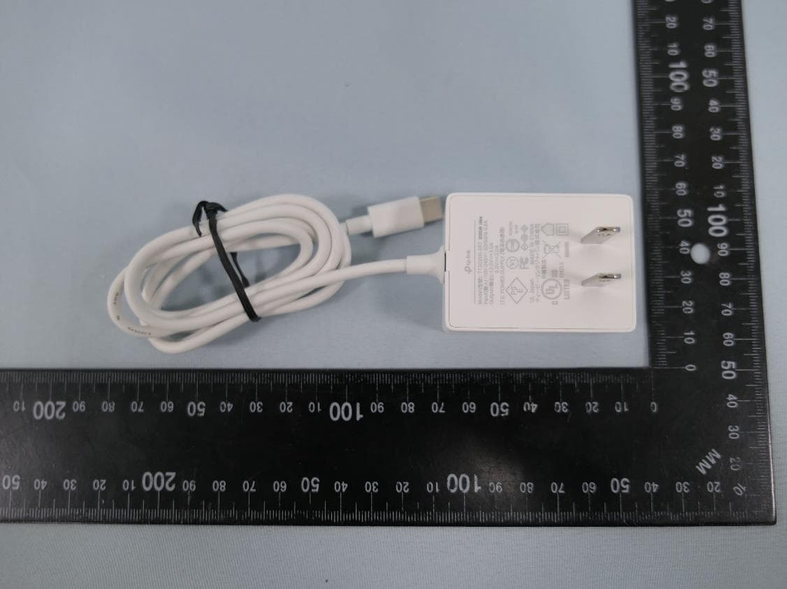
2AXJ4AIRE5
Jan 15, 2024AX3000 Wi-Fi 6 Air Range Extender
Equipment Class
DTS - Digital Transmission System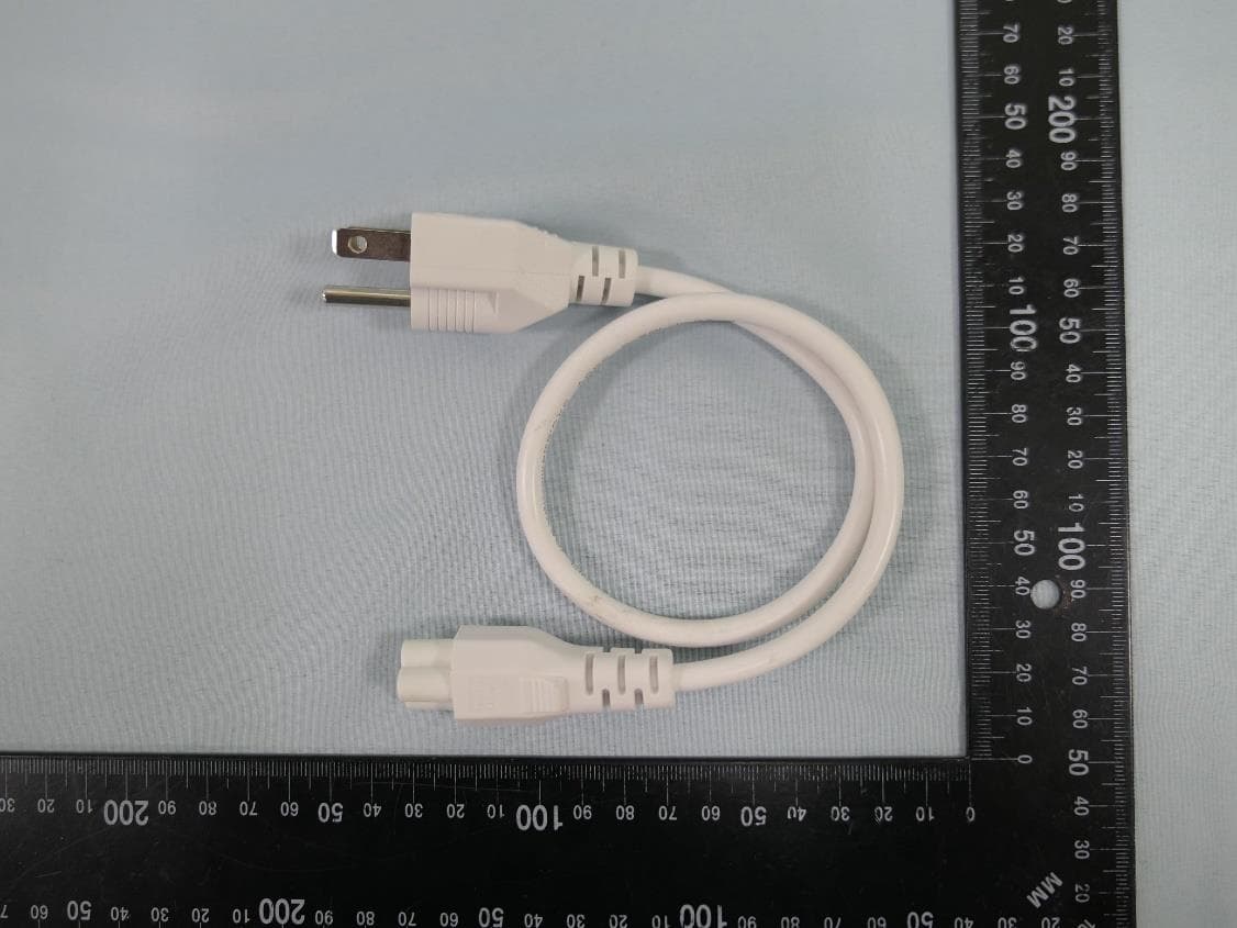
2AXJ4EAP115BRG
Jan 11, 20245GHz 300Mbps Long-range Indoor/Outdoor Access Point
Equipment Class
NII - Unlicensed National Information Infrastructure TX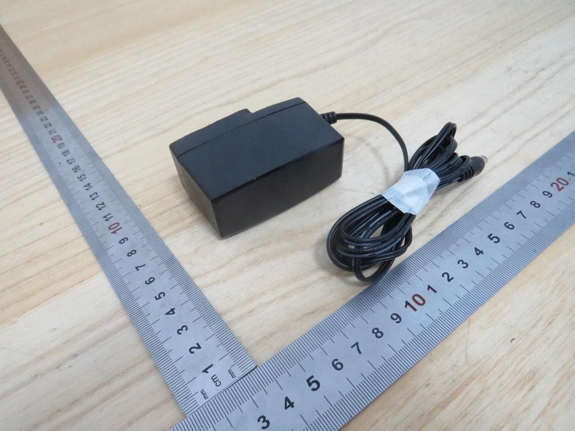
2AXJ4HX510V2
Jan 10, 2024AX3000 Whole Home Mesh Wi-Fi AP
Equipment Class
NII - Unlicensed National Information Infrastructure TX
2AXJ4EAP215BRG
Dec 11, 20235GHz 867Mbps Long-range Indoor/Outdoor Access Point
Equipment Class
NII - Unlicensed National Information Infrastructure TX