2AXJ4AX72PROAX5400 Multi-Gigabit Wi-Fi 6 Router
TP-Link Corporation Limited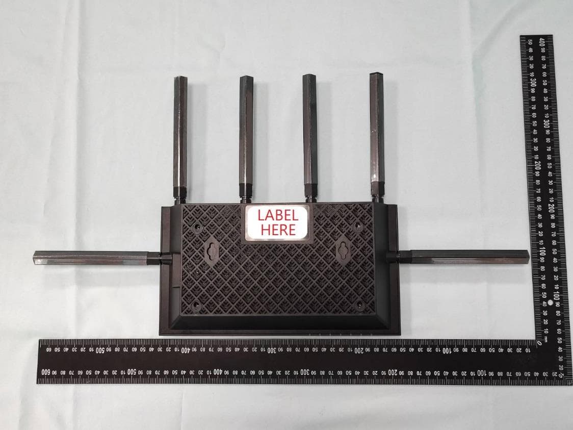
Click to zoom
Application Details
- Equipment Class
- NII - Unlicensed National Information Infrastructure TX
- Date of Grant
- Dec 01, 2022
- Application Purpose
- Original Equipment
- Date of Application
- Nov 26, 2022
- Equipment Note
- AX5400 Multi-Gigabit Wi-Fi 6 Router
- Frequency Range
- 5570.00000000 - 5570.00000000
- Company
- TP-Link Corporation Limited
- Country
- Hong Kong
Documents & Files
Document Text
Text extracted from the exhibit documents filed with the FCC. Open a document above to read the original.
Users Manual
© 2022 TP-Link 1910013167 REV1.0.0 User Guide AX5400 Multi-Gigabit Wi-Fi 6 Router Archer AX72 Pro Contents About This Guide 1 Chapter 1 Get to Know About Your Router 3 1. 1. Product Overview. . . . . . . . . . . . . . . . . . . . . . . . . . . . . . . . . . . . . . . . . . . . . . . . . . . . . . . . . . . . 4 1. 2. Appearance . . . . . . . . . . . . . . . . . . . . . . . . . . . . . . . . . . . . . . . . . . . . . . . . . . . . . . . . . . . . . . . . . 4 1. 2. 1. Top Panel . . . . . . . . . . . . . . . . . . . . . . . . . . . . . . . . . . . . . . . . . . . . . . . . . . . . . . . . . . . . . 4 1. 2. 2. Back Panel . . . . . . . . . . . . . . . . . . . . . . . . . . . . . . . . . . . . . . . . . . . . . . . . . . . . . . . . . . . . 5 1. 2. 3. Side Panel. . . . . . . . . . . . . . . . . . . . . . . . . . . . . . . . . . . . . . . . . . . . . . . . . . . . . . . . . . . . . 6 Chapter 2 Connect the Hardware 7 2. 1. Position Your Router . . . . . . . . . . . . . . . . . . . . . . . . . . . . . . . . . . . . . . . . . . . . . . . . . . . . . . . . . 8 2. 2. Connect Your Router. . . . . . . . . . . . . . . . . . . . . . . . . . . . . . . . . . . . . . . . . . . . . . . . . . . . . . . . . 8 Chapter 3 Log In to Your Router 11 Chapter 4 Set Up Internet Connection 13 4. 1. Use Quick Setup Wizard . . . . . . . . . . . . . . . . . . . . . . . . . . . . . . . . . . . . . . . . . . . . . . . . . . . .14 4. 2. Quick Setup Via TP-Link Tether App. . . . . . . . . . . . . . . . . . . . . . . . . . . . . . . . . . . . . . . . .14 4. 3. Manually Set Up Your Internet Connection . . . . . . . . . . . . . . . . . . . . . . . . . . . . . . . . . .15 4. 4. Set Up the Router as an Access Point . . . . . . . . . . . . . . . . . . . . . . . . . . . . . . . . . . . . . . .18 4. 5. Set Up an IPv6 Internet Connection. . . . . . . . . . . . . . . . . . . . . . . . . . . . . . . . . . . . . . . . .18 Chapter 5 TP-Link Cloud Service 22 5. 1. Register a TP-Link ID. . . . . . . . . . . . . . . . . . . . . . . . . . . . . . . . . . . . . . . . . . . . . . . . . . . . . . . .23 5. 2. Change Your TP-Link ID Information. . . . . . . . . . . . . . . . . . . . . . . . . . . . . . . . . . . . . . . . .23 5. 3. Manage the User TP-Link IDs . . . . . . . . . . . . . . . . . . . . . . . . . . . . . . . . . . . . . . . . . . . . . . .24 5. 3. 1. Add TP-Link ID to Manage the Router. . . . . . . . . . . . . . . . . . . . . . . . . . . . . . . . .25 5. 3. 2. Remove TP-Link ID(s) from Managing the Router. . . . . . . . . . . . . . . . . . . . . .25 5. 4. Manage the Router via the TP-Link Tether App . . . . . . . . . . . . . . . . . . . . . . . . . . . . . .26 Chapter 6 Network Map 27 Chapter 7 Wireless Settings 31 7. 1. Specify Wireless Settings . . . . . . . . . . . . . . . . . . . . . . . . . . . . . . . . . . . . . . . . . . . . . . . . . .32 7. 2. Schedule Your Wireless Function . . . . . . . . . . . . . . . . . . . . . . . . . . . . . . . . . . . . . . . . . . .34 7. 3. Use WPS for Wireless Connection . . . . . . . . . . . . . . . . . . . . . . . . . . . . . . . . . . . . . . . . . .35 7. 3. 1. Connect via the Client’s PIN . . . . . . . . . . . . . . . . . . . . . . . . . . . . . . . . . . . . . . . . . .35 7. 3. 2. Connect via the Router’s PIN . . . . . . . . . . . . . . . . . . . . . . . . . . . . . . . . . . . . . . . . .36 7. 3. 3. Push the WPS Button. . . . . . . . . . . . . . . . . . . . . . . . . . . . . . . . . . . . . . . . . . . . . . . . .36 7. 4. Advanced Wireless Settings . . . . . . . . . . . . . . . . . . . . . . . . . . . . . . . . . . . . . . . . . . . . . . . .36 Chapter 8 Guest Network 39 8. 1. Create a Network for Guests . . . . . . . . . . . . . . . . . . . . . . . . . . . . . . . . . . . . . . . . . . . . . . .40 8. 2. Set Up Portal Authentication for the Guest Network . . . . . . . . . . . . . . . . . . . . . . . . .41 8. 3. Limit the Bandwidth of the Guest Network. . . . . . . . . . . . . . . . . . . . . . . . . . . . . . . . . . .42 8. 4. Specify the Effective Time of the Guest Network. . . . . . . . . . . . . . . . . . . . . . . . . . . .43 8. 5. Customize Guest Network Options. . . . . . . . . . . . . . . . . . . . . . . . . . . . . . . . . . . . . . . . . .44 Chapter 9 USB Settings 46 9. 1. Access the USB Storage Device . . . . . . . . . . . . . . . . . . . . . . . . . . . . . . . . . . . . . . . . . . . .47 9. 1. 1. Access the USB Device Locally. . . . . . . . . . . . . . . . . . . . . . . . . . . . . . . . . . . . . . .47 9. 1. 2. Access the USB Device Remotely . . . . . . . . . . . . . . . . . . . . . . . . . . . . . . . . . . . .48 9. 1. 3. Customize the Access Settings. . . . . . . . . . . . . . . . . . . . . . . . . . . . . . . . . . . . . . .50 9. 2. Media Sharing . . . . . . . . . . . . . . . . . . . . . . . . . . . . . . . . . . . . . . . . . . . . . . . . . . . . . . . . . . . . . .52 9. 3. Time Machine . . . . . . . . . . . . . . . . . . . . . . . . . . . . . . . . . . . . . . . . . . . . . . . . . . . . . . . . . . . . . .53 Chapter 10 HomeShield 55 10. 1. Network Security . . . . . . . . . . . . . . . . . . . . . . . . . . . . . . . . . . . . . . . . . . . . . . . . . . . . . . . . . . .56 10. 2. Parental Controls . . . . . . . . . . . . . . . . . . . . . . . . . . . . . . . . . . . . . . . . . . . . . . . . . . . . . . . . . . .56 10. 3. Network Analysis & Optimization. . . . . . . . . . . . . . . . . . . . . . . . . . . . . . . . . . . . . . . . . . . .57 Chapter 11 OneMesh with Seamless Roaming 59 11. 1. Set Up a OneMesh Network. . . . . . . . . . . . . . . . . . . . . . . . . . . . . . . . . . . . . . . . . . . . . . . . .60 11. 2. Manage Devices in the OneMesh Network . . . . . . . . . . . . . . . . . . . . . . . . . . . . . . . . . .62 Chapter 12 Network Security 64 12. 1. Protect the Network from Cyber Attacks . . . . . . . . . . . . . . . . . . . . . . . . . . . . . . . . . . . .65 12. 2. Access Control . . . . . . . . . . . . . . . . . . . . . . . . . . . . . . . . . . . . . . . . …
Text truncated - open the document above for the full version.
Users Manual
36 Chapter 7 Wireless Settings Note: • The Effective Time Schedule is based on the time of the router. You can go to Advanced > System > Time & Language to modify the time. • The wireless network will be automatically turned on after the time period you set. 7 3 Use WPS for Wireless Connection Wi-Fi Protected Setup (WPS) provides an easier approach to set up a security-protected Wi-Fi connection. 1. Visit http://tplinkwifi.net, and log in with your TP-Link ID or the password you set for the router. 2. Make sure the Wi-Fi of your router is on and go to Advanced > Wireless > WPS. 7 3 1 Connect via the Client’s PIN Enter the PIN of your device and click Connect. Then your device will get connected to the router. 37 Chapter 7 Wireless Settings 7 3 2 Connect via the Router’s PIN Select Router’s PIN in Method 1 to enable Router’s PIN. You can use the default PIN or generate a new one. Note: PIN (Personal Identification Number) is an eight-character identification number preset to each router. WPS supported devices can connect to your router with the PIN. The default PIN is printed on the label of the router. 7 3 3 Push the WPS Button Click Start on the screen or directly press the router’s WPS button. Within two minutes, enable WPS on your personal device. Success will appear on the screen and the WPS LED of the router should change from flashing to solid on, indicating successful WPS connection. 7 4 Advanced Wireless Settings Check advanced wireless settings for your device. 38 Chapter 7 Wireless Settings 1. Visit http://tplinkwifi.net, and log in with your TP-Link ID or the password you set for the router. 2. Go to Advanced > Wireless > Additional Settings. 3. Configure advanced wireless settings. • WMM - WMM function can guarantee the packets with high-priority messages being transmitted preferentially. • AP Isolation - This function isolates all connected wireless stations so that wireless stations cannot access each other through WLAN. • Airtime Fairness - This function can improve the overall network performance by sacrificing a little bit of network time on your slow devices. • Zero Wait DFS - Zero Wait DFS (Dynamic Frequency Selection) allows the router to immediately reselect a new channel once the radar signal is detected on a channel allocated to radar devices to ensure lag-free network experience. • Beacon Interval - Enter a value between 40 and 1000 in milliseconds to determine the duration between beacon packets that are broadcasted by the router to synchronize the wireless network. The default value is 100 milliseconds. • RTS Threshold- Enter a value between 1 and 2346 to determine the packet size of data transmission through the router. By default, the RTS (Request to Send) Threshold size is 2346. If the packet size is greater than the preset threshold, the router will send RTS frames to a particular receiving station and negotiate the sending of a data frame. • DTIM Interval - The value determines the interval of DTIM (Delivery Traffic Indication Message). Enter a value between 1 and 15 intervals. The default value is 1, which indicates the DTIM Interval is the same as Beacon Interval. 39 Chapter 7 Wireless Settings • Group Key Update Period - Enter a number of seconds (minimum 30) to control the time interval for the encryption key automatic renewal. The default value is 0, meaning no key renewal. Chapter 8 Guest Network This function allows you to provide Wi-Fi access for guests without disclosing your main network. When you have guests in your house, apartment, or workplace, you can create a guest network for them. In addition, you can customize the guest network according to your needs. It contains the following sections: • Create a Network for Guests • Set Up Portal Authentication for the Guest Network • Limit the Bandwidth of the Guest Network • Specify the Effective Time of the Guest Network • Customize Guest Network Options 41 Chapter 8 Guest Network 8 1 Create a Network for Guests 1. Visit http://tplinkwifi.net, and log in with your TP-Link ID or the password you set for the router. 2. Go to Wireless and locate the Guest Network section. 3. Create a guest network as needed. 1 ) Enable 2.4GHz and/or 5GHz. 2 ) Customize the SSID. Don‘t select Hide SSID unless you want your guests to manually input the SSID for guest network access. 3 ) Select the Security type and customize your own password. If No security is selected, no password is needed to access your guest network. 4. Click S AV E. Now your guests can access your guest network using the SSID and password you set! 5. You can also click Share Network to share the SSID and password to your guests. Tips: To view guest network information, go to Network Map and locate the Guest Network section. You can turn on or off the guest network function conveniently. 42 Chapter 8 Guest Network 8 2 Set Up Portal Authentication for the Guest Network Imagine that you run a small shop and provide a guest network for your customers. You want to seize every opportunity to promote your shop, which makes portal authentication an excellent choice. Customers will be directed to a web page for access verification, on which your personalized promotion is displayed. Moreover, you can specify a web link so that newly connected guests will be redirected to, for example, the official website of your shop. 1. Visit http://tplinkwifi.net, and log in with your TP-Link ID or the password you set for the router. 2. Go to Wireless and locate the Guest Network section. 3. Set Security to Portal. 4. Select the Authentication Type. • If you select No Authentication, guests can access the network without any authentication. • If you select Simple Password, specify a password for authentication. 5. Specify the Authentication Timeout. When a guest’s authentication expires, they have to reconnect to the network. The default value Always indicates that authentication will never time out. 43 Chapter 8 Guest Network 6. (Optional) Enable Redirect and enter your…
Text truncated - open the document above for the full version.
Users Manual
84 Chapter 14 VPN Server&Client 6. Enter the User name and Password you have set for the PPTP VPN server on your router, and click Connect. 7. Click Connect Now when the VPN connection is ready to use. 85 Chapter 14 VPN Server&Client 14 3 Use L2TP/IPSec VPN to Access Your Home Network L2TP/IPSec VPN Server is used to create a L2TP/IPSec VPN connection for remote devices to access your home network. To use the VPN feature, you need to set up L2TP/IPSec VPN Server on your router, and configure the L2TP/IPSec connection on remote devices. Please follow the steps below to set up the L2TP/IPSec VPN connection. INTERNET Home NetworkRouter (VPN Server)Remote Devices Step 1 Set up L2TP/IPSec VPN Server on Your Router 1. Visit http://tplinkwifi.net, and log in with your TP-Link ID or the password you set for the router. 2. Go to Advanced > VPN Server > L2TP/IPSec, and enable L2TP/IPSec. Note: • Firmware update may be required to support L2TP/IPSec VPN Server. • Before you enable VPN Server, we recommend you configure Dynamic DNS Service (recommended) or assign a static IP address for router’s WAN port and synchronize your System Time with internet. 86 Chapter 14 VPN Server&Client 3. In the Client IP Address field, enter the range of IP addresses (up to 10) that can be leased to the devices by the L2TP/IPSec VPN server. 4. Keep IPSec Encryption as Encrypted and create an IPSec Pre-Shared Key. 5. Click S AV E. 6. Configure the L2TP/IPSec VPN connection account for the remote device. You can create up to 16 accounts. 4 ) Click Add. 5 ) Enter the Username and Password to authenticate devices to the L2TP/IPSec VPN Server. 6 ) Click ADD. Step 2 Configure L2TP/IPSec VPN Connection on Your Remote Device 87 Chapter 14 VPN Server&Client The remote device can use the Windows or Mac OS built-in L2TP/IPSec software or a third-party L2TP/IPSec software to connect to L2TP/IPSec Server. Here we use the Windows built-in L2TP/IPSec software as an example. 1. Go to Start > Control Panel > Network and Internet > Network and Sharing Center. 2. Select Set up a new connection or network. 3. Select Connect to a workplace and click Next. 88 Chapter 14 VPN Server&Client 4. Select Use my Internet connection (VPN). 5. Enter the internet IP address of the router (for example: 218.18.1.73) in the Internet address field, and select the checkbox Don’t connect now; just set it up so I can connect later. Click Next. 6. Enter the User name and Password you have set for the L2TP/IPSec VPN server on your router, and click Connect. 89 Chapter 14 VPN Server&Client 7. Click Close when the VPN connection is ready to use 8. Go to Network and Sharing Center and click Change adapter settings. 90 Chapter 14 VPN Server&Client 9. Find the VPN connection you created, then double-click it. 10. Enter the User name and Password you have set for the L2TP/IPSec VPN server on your router, and click Properties. 91 Chapter 14 VPN Server&Client 11. Switch to the Security tab, select Layer 2 Tunneling Protocol with IPsec (L2TP/ IPSec) and click Advanced settings. 12. Select Use preshared key for authentication and enter the IPSec Pre-Shared Key you have set for the L2TP/IPSec VPN server on your router. Then click OK. Done! Click Connect to start VPN connection. 92 Chapter 14 VPN Server&Client 14 4 Use VPN Client to Access a Remote VPN Server VPN Client is used to create VPN connections for devices in your home network to access a remote VPN server. To use the VPN feature, simply configure a VPN connection and choose your desired devices on your router, then these devices can access the remote VPN server. Please follow the steps below: INTERNET Home DevicesRouter (VPN Client)VPN Servers 1. Visit http://tplinkwifi.net, and log in with your TP-Link ID or the password you set for the router. 2. Go to Advanced > VPN Client. Note: Firmware update may be required to support VPN Client. 3. Enable VPN Client, then save the settings. 4. Add VPN servers, and enable the one you need. 1 ) In the Server List section, click Add. 2 ) Specify a description for the VPN, and choose the VPN type. 93 Chapter 14 VPN Server&Client 3 ) Enter the VPN information provided by your VPN provider. • OpenVPN: Enter the VPN username and password if required by your VPN provider, otherwise simply leave them empty. Then import the configuration file provided by your VPN provider. • PPTP: Enter the VPN server address (for example: 218.18.1.73) and the VPN username and password provided by your VPN provider. 94 Chapter 14 VPN Server&Client • L2TP/IPSec VPN: Enter the VPN server address (for example: 218.18.1.73), VPN username and password, and IPSec pre-shared key provided by your VPN provider. 4 ) Save the settings. 5 ) In the server list, enable the one you need. 95 Chapter 14 VPN Server&Client 5. Add and manage the devices that will use the VPN function. 1 ) In the Device List section, click Add. 2 ) Choose and add the devices that will access the VPN server you have configured. 6. Save the settings. 96 Chapter 14 VPN Server&Client Done! Now the devices you specified can access the VPN server you enabled. Chapter 15 Customize Your Network Settings This chapter guides you on how to configure advanced network features. It contains the following sections: • Change the LAN Settings • Set Up Link Aggregation • Configure to Support IPTV Service • Specify DHCP Server Settings • Set Up a Dynamic DNS Service Account • Create Static Routes 98 Chapter 15 Customize Your Network Settings 15 1 Change the LAN Settings The router is preset with a default LAN IP 192.168.0.1, which you can use to log in to its web management page. The LAN IP address together with the Subnet Mask also defines the subnet that the connected devices are on. If the IP address conflicts with another device on your local network or your network requires a specific IP subnet, you can change it. 1. Visit http://tplinkwifi.net, and log in with your TP-Link ID or the password you set for the router. 2. Go to Advanced > Network > L…
Text truncated - open the document above for the full version.
Users Manual
116 Chapter 16 Manage the Router 4. In the Save Log section, click SAVE TO LOCAL to save the system logs to a local disk. • To send the system log to a mailbox at a fixed time: For example, I want to check my router’s working status at a fixed time every day, however, it’s too troublesome to log in to the web management page every time I want to go checking. It would be great if the system logs could be sent to my mailbox at 8 a.m. every day. 1. Visit http://tplinkwifi.net, and log in with your TP-Link ID or the password you set for the router. 2. Go to Advanced > System Tools > System Log. 3. In the Save Log section, click MAIL LOG. 4. Enter the information required: 117 Chapter 16 Manage the Router 1 ) Email From: Enter the email address used for sending the system log. 2 ) Select Require Password. Tips: Generally, Require Password should be selected if the login of the mailbox requires username and password. 3 ) Username: Enter the email address used for sending the system log. 4 ) Email Password: Enter the password to login the sender’s email address. 5 ) SMTP Server: Enter the SMTP server address. Tips: SMTP server is available for users in most webmail systems. For example, the SMTP server address of Hotmail is smtp-mail.outlook.com. 6 ) Email To: Enter the recipient’s email address, which can be the same as or different from the sender’s email address. 7 ) Select Mail Log Automatically. Tips: The router will send the system log to the designated email address if this option is enabled. 8 ) Frequency: This determines how often the recipient will receive the system log . 5. Click S AV E. 16 8 Test the Network Connectivity Diagnostics is used to test the connectivity between the router and the host or other network devices. 118 Chapter 16 Manage the Router 1. Visit http://tplinkwifi.net, and log in with your TP-Link ID or the password you set for the router. 2. Go to Advanced > System > Diagnostics. 3. Enter the information: 1 ) Choose Ping or Traceroute as the diagnostic tool to test the connectivity; • Ping is used to test the connectivity between the router and the tested host, and measure the round-trip time. • Traceroute is used to display the route (path) your router has passed to reach the tested host, and measure transit delays of packets across an Internet Protocol network. 2 ) Enter the IP Address or Domain Name of the tested host. 3 ) Modify the Ping Count number and the Ping Packet Size. It’s recommended to keep the default value. 4 ) If you have chosen Traceroute, you can modify the Traceroute Max TTL. It’s recommended to keep the default value. 4. Click S TA R T to begin the diagnostics. The figure below indicates the proper connection between the router and the Yahoo server (www.Yahoo.com) tested through Ping. 119 Chapter 16 Manage the Router The figure below indicates the proper connection between the router and the Yahoo server (www.Yahoo.com) tested through Traceroute. 16 9 Set System Time and Language System time is the time displayed while the router is running. The system time you configure here will be used for other time-based functions like Parental Controls. You can choose the way to obtain the system time as needed. System language is the language displayed when you log into the router. You can change the system language as needed. 1. Visit http://tplinkwifi.net, and log in with your TP-Link ID or the password you set for the router. 2. Go to Advanced > System > Time & Language. • To get time from the internet: 1. Enable 24-Hour Time if you want the time to display in a 24-hour way. 2. In the Set Time field, select Get from Internet. 3. Select your local Time Zone from the drop-down list. 120 Chapter 16 Manage the Router 4. In the NTP Server I field, enter the IP address or domain name of your desired NTP Server. 5. (Optional) In the NTP Server II field, enter the IP address or domain name of the second NTP Server. 6. Click S AV E. • To get time from your computer: 1. In the Set Time field, select Get from Managing Device. 2. The time of your computer will then be displayed and click S AV E. • To manually set the date and time: 1. In the Set Time field, select Manually. 2. Set the current Date (In MM/DD/YYYY format). 3. Set the current Time (In HH/MM/SS format). 4. Click S AV E. • To set Daylight Saving Time: 1. Tick the Enable box of Daylight Saving Time. 121 Chapter 16 Manage the Router 2. Select the correct Start date and time when daylight saving time starts at your local time zone. 3. Select the correct End date and time when daylight saving time ends at your local time zone. 4. Click S AV E. • To set system language: Select the language from the dropdown list, then click S AV E. 16 10 Set the Router to Reboot Regularly The Scheduled Reboot feature cleans the cache to enhance the running performance of the router. 1. Visit http://tplinkwifi.net, and log in with your TP-Link ID or the password you set for the router. 2. Go to Advanced > System > Reboot. 3. Tick the Enable box of Reboot Schedule. 122 Chapter 16 Manage the Router 4. Specify the Reboot Time when the router reboots and Repeat to decide how often it reboots. 5. Click S AV E. 16 11 Control the LED The LED of the router indicates its activities and status. You can enable the Night Mode feature to specify a time period during which the LED is off. 1. Visit http://tplinkwifi.net, and log in with your TP-Link ID or the password you set for the router. 2. Go to Advanced > System > LED Control. 3. Enable Night Mode. 4. Specify the LED off time, and the LED will be off during this period every day. 5. Click S AV E. 123 FAQ Q1 What should I do if I forget my wireless password? The default wireless password is printed on the label of the router. If the password has been altered: 1. Connect your computer to the router using an Ethernet cable. 2. Visit http://tplinkwifi.net, and log in with your TP-Link ID or the password you set for the router. 3. Go to Wireless to retrieve or reset your wireless passwo…
Text truncated - open the document above for the full version.
Cover Letter(s)
Confidentiality Request Letter Federal Communications Commission Authorization and Evaluation Division FCC ID: 2AXJ4AX72PRO Confidentiality Request Pursuant to Sections 0.457 and 0.459 of the Commission’s Rules, we hereby request confidential treatment of information accompanying this application as outlined below: 1. Block Diagram 2. Schematics 3. Operational Description The above materials contain trade secrets and proprietary information not customarily released to the public. The public disclosure of these matters might be harmful to the applicant and provide unjustified benefits to its competitors. The applicant understands that pursuant to Rule 0.457, disclosure of this application and all accompanying documentation will not be made before the date of the Grant for this application. Sincerely, _________________ Name: Sarah Wang Position: Regulatory Compliance Manager Date: 2022-11-11
Cover Letter(s)
Declaration of Authorization We Name: TP-Link Corporation Limited Address: Room 901, 9/F., New East Ocean Centre, 9 Science Museum Road, Tsim Sha Tsui, Kowloon, Hongkong Declare that: Name Representative of agent: Marlin Chen Agent Company name: MRT Technology (Suzhou) Co., Ltd Address: D8 Building, Youxin Industrial Park, No.2 Tian'edang Rd., Wuzhong Economic Development Zone City: Suzhou Country: China is authorized to apply for Certification of the following product(s): Product: AX5400 Multi-Gigabit Wi-Fi 6 Router FCC ID: 2AXJ4AX72PRO Model: Archer AX72 Pro, EX710 Pro Brand: tp-link Sincerely, _________________ Name: Sarah Wang Position: Regulatory Compliance Manager Date: 2022-11-11
Cover Letter(s)
Declaration of Conformity We Name: TP-Link Corporation Limited Address: Room 901, 9/F., New East Ocean Centre, 9 Science Museum Road, Tsim Sha Tsui, Kowloon, Hongkong Declare that: Product: AX5400 Multi-Gigabit Wi-Fi 6 Router FCC ID: 2AXJ4AX72PRO Model: Archer AX72 Pro, EX710 Pro Brand: tp-link Product which bears the above FCC ID is also compliant with the FCC requirements for sDOC. And the sDOC procedure shall be carried out prior to marketing the device in the US. Sincerely, _________________ Name: Sarah Wang Position: Regulatory Compliance Manager Date: 2022-11-11
Cover Letter(s)
Non-SDR (Software Defined Radio) Cover Letter Refer to KDB 442812 D01 SDR apps Guide v02r03. The following six questions can be used for determining if a radio can elect to be, or must be an SDR. 1. Can the RF parameters of the device be altered through software? Yes - go to 2. No, not an SDR No 2. Can third parties not permitted by the Commission through specific filings modify, configure, or load different software, or make configuration settings to operate the device or host hardware radio frequency parameters (frequency range, modulation type, maximum output power or other radio parameters) in any other way than granted (or expected to be granted)? Yes, must be an SDR. No - go to 3. No 3. Is the device capable of operating in any other in any other way than granted, or will be, granted? Yes, - go to 4. No - go to 5. No 4. Is this a Part 15 client Device as defined in Section 15.202 (as opposed to a master device)? Yes, qualifies as a part 15 client devices - go to 5. No, must be an SDR. 5. Does the manufacturer elect SDR? Yes, elects to be an SDR. No, Not an SDR No Conclusion: According to the above questions reply, we can confirm this device (FCC ID: 2AXJ4AX72PRO & IC: 26583-AX72PRO) must be a Non-SDR device. __________________ Name: Sarah Wang Position: Regulatory Compliance Manager Date: 2022-11-11
External Photos
Report No.: 2208TW0121-External Photo Product: AX5400 Multi-Gigabit Wi-Fi 6 Router Brand Name: tp-link Model Number: Archer AX72 Pro 1 of 7 External Photograph (1) EUT Photo (2) EUT Photo Report No.: 2208TW0121-External Photo 2 of 7 (3) EUT Photo (4) EUT Photo Report No.: 2208TW0121-External Photo 3 of 7 (5) EUT Photo (6) EUT Photo Report No.: 2208TW0121-External Photo 4 of 7 (7) Adapter(Brand: MASS POWER ,M/N: NBS30D120250VU) (8) Adapter(Brand: MASS POWER ,M/N: NBS30D120250VU) Report No.: 2208TW0121-External Photo 5 of 7 (9) Adapter(Brand: MASS POWER ,M/N: NBS30D120250VU) (10) Adapter(Brand: MASS POWER ,M/N: NBS30D120250VU) Report No.: 2208TW0121-External Photo 6 of 7 (11) Adapter(Brand: MASS POWER ,M/N: NBS30D120250VU) (12) Adapter(Brand: MASS POWER ,M/N: NBS30D120250VU) Report No.: 2208TW0121-External Photo 7 of 7 (13) Adapter(Brand: MASS POWER ,M/N: NBS30D120250VU)
ID Label/Location Info
Label and Label Location
Internal Photos
Report No.: 2208TW0121-Internal Photo Product: AX5400 Multi-Gigabit Wi-Fi 6 Router Brand Name: tp-link Model Number: Archer AX72 Pro 1 of 7 Internal Photograph (1) EUT Photo (2) EUT Photo Report No.: 2208TW0121-Internal Photo 2 of 7 (3) EUT Photo (4) EUT Photo Report No.: 2208TW0121-Internal Photo 3 of 7 (5) EUT Photo (6) EUT Photo Report No.: 2208TW0121-Internal Photo 4 of 7 (7) EUT Photo (8) EUT Photo Report No.: 2208TW0121-Internal Photo 5 of 7 (9) EUT Photo (10) EUT Photo Report No.: 2208TW0121-Internal Photo 6 of 7 (11) EUT Photo (12) EUT Photo Report No.: 2208TW0121-Internal Photo 7 of 7 (13) EUT Photo
RF Exposure Info
MRT Technology (Taiwan) Co., Ltd Report No.: 2208TW0121-U4 Phone: +886-3-3288388 Report Version 1.0 Web: www.mrt-cert.com Issue Date: 2022-11-15 FCC ID: 2AXJ4AX72PRO Page Number: 1 of 14 RF Exposure Evaluation Declaration FCC ID : 2AXJ4AX72PRO Applicant : TP-Link Technologies Co., Ltd. Application Type : Certification Product : AX5400 Multi-Gigabit Wi-Fi 6 Router Model No. : Archer AX72 Pro, EX710 Pro Brand Name : tp-link FCC Classification : Digital Transmission System (DTS) Unlicensed National Information Infrastructure (NII) FCC Rule Part(s) : FCC Part 2.1091 Result : Complies Test By : ( Owen Tsai ) Reviewed By : ( Paddy Chen ) Approved By : ( Chenz Ker) The test results relate only to the samples tested. The test results shown in the test report are traceable to the national/international standards through the calibration of the equipment and evaluated measurement uncertainty herein. The test report shall not be reproduced except in full without the written approv…
Text truncated - open the document above for the full version.
Contact Information
Applicant
Sarah Wang
Technical Contact
MRT Technology (Suzhou) Co., LtdRobin Wu
[email protected]86-512-66308358
D8 Building, Youxin Industrial Park, · Suzhou · China
Non-Technical Contact
MRT Technology (Suzhou) Co., LtdRobin Wu
[email protected]0512-66308358
Test Firm
MRT Technology (Taiwan) Co.,LtdChenz Ker
Technical Specifications
| # | Rule Parts | Frequency Range | Power Output |
|---|---|---|---|
| 6 | 15E | 5.57 GHz - 5.57 GHz | 221.30 mW |
Other Applications from TP-Link Corporation Limited
2AXJ4TXE50UH
Jan 28, 2024AXE3000 Wi-Fi 6E High Gain Wireless USB Adapter
Equipment Class
NII - Unlicensed National Information Infrastructure TX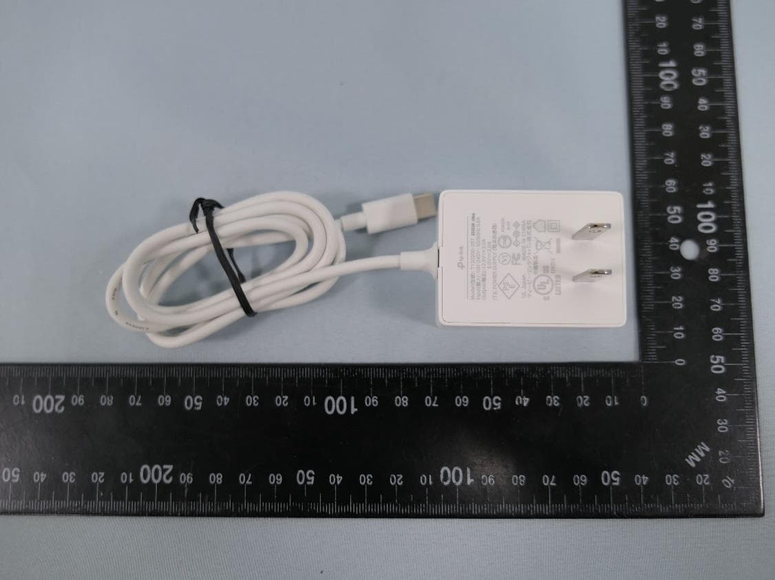
2AXJ4AIRE5
Jan 15, 2024AX3000 Wi-Fi 6 Air Range Extender
Equipment Class
DTS - Digital Transmission System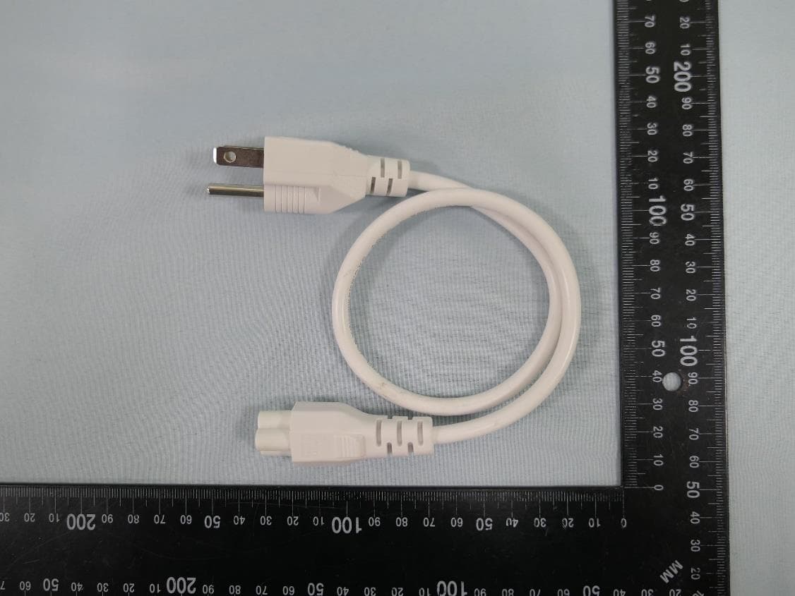
2AXJ4EAP115BRG
Jan 11, 20245GHz 300Mbps Long-range Indoor/Outdoor Access Point
Equipment Class
NII - Unlicensed National Information Infrastructure TX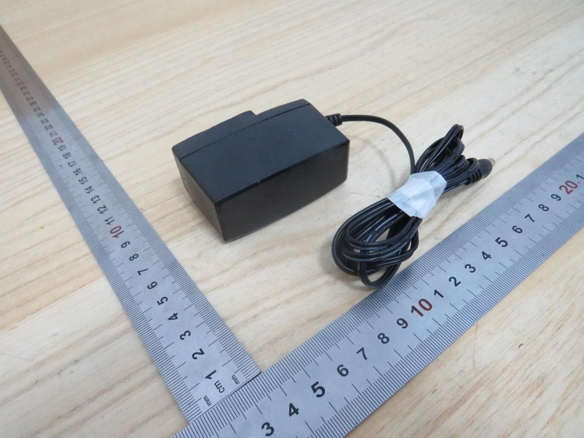
2AXJ4HX510V2
Jan 10, 2024AX3000 Whole Home Mesh Wi-Fi AP
Equipment Class
NII - Unlicensed National Information Infrastructure TX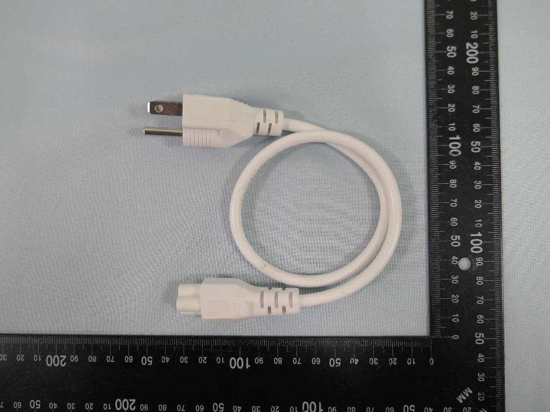
2AXJ4EAP215BRG
Dec 11, 20235GHz 867Mbps Long-range Indoor/Outdoor Access Point
Equipment Class
NII - Unlicensed National Information Infrastructure TX