2AXJ4C86AC1900 MU-MIMO Wi-Fi Router
TP-Link Corporation Limited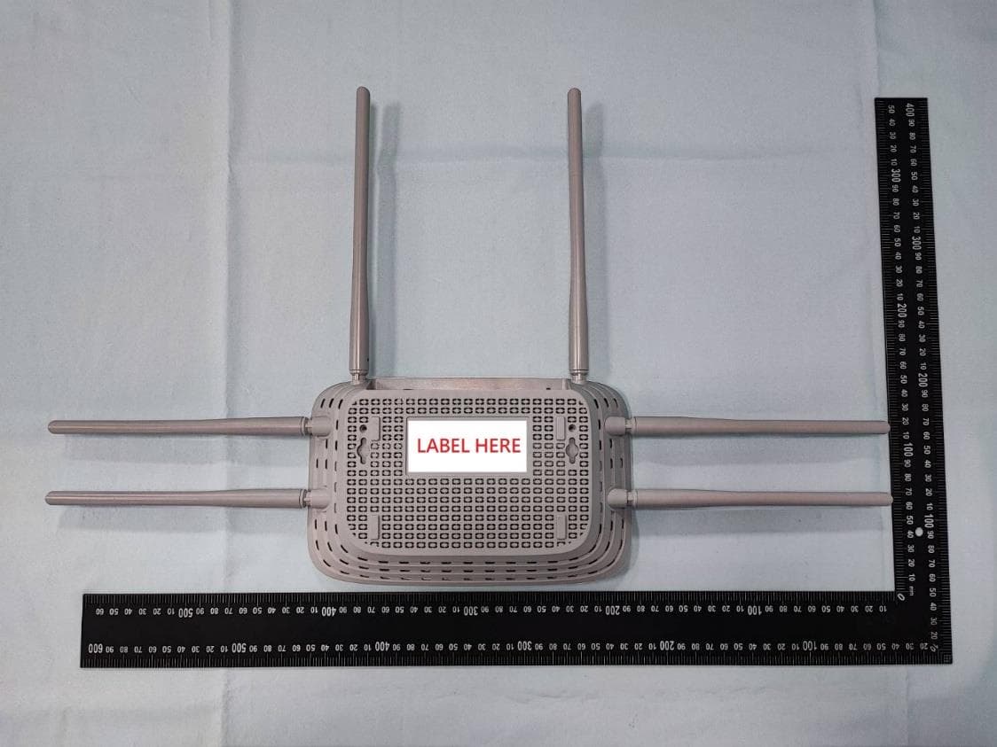
Click to zoom
Application Details
- Equipment Class
- NII - Unlicensed National Information Infrastructure TX
- Date of Grant
- Jan 20, 2023
- Application Purpose
- Original Equipment
- Date of Application
- Jan 18, 2023
- Equipment Note
- AC1900 MU-MIMO Wi-Fi Router
- Frequency Range
- 5745.00000000 - 5845.00000000
- Company
- TP-Link Corporation Limited
- Country
- Hong Kong
Documents & Files
Document Text
Text extracted from the exhibit documents filed with the FCC. Open a document above to read the original.
Users Manual
© 2022 TP-Link 1910013272 REV1.0.0 User Guide AC1900 MU-MIMO Wi-Fi Router Archer C86 Contents About This Guide 1 Chapter 1 Get to Know About Your Router 3 1. 1. Product Overview. . . . . . . . . . . . . . . . . . . . . . . . . . . . . . . . . . . . . . . . . . . . . . . . . . . . . . . . . . . . 4 1. 2. Appearance . . . . . . . . . . . . . . . . . . . . . . . . . . . . . . . . . . . . . . . . . . . . . . . . . . . . . . . . . . . . . . . . . 4 1. 2. 1. Top Panel . . . . . . . . . . . . . . . . . . . . . . . . . . . . . . . . . . . . . . . . . . . . . . . . . . . . . . . . . . . . . 4 1. 2. 2. Back Panel . . . . . . . . . . . . . . . . . . . . . . . . . . . . . . . . . . . . . . . . . . . . . . . . . . . . . . . . . . . . 6 Chapter 2 Connect the Hardware 7 2. 1. Position Your Router . . . . . . . . . . . . . . . . . . . . . . . . . . . . . . . . . . . . . . . . . . . . . . . . . . . . . . . . . 8 2. 2. Connect Your Router. . . . . . . . . . . . . . . . . . . . . . . . . . . . . . . . . . . . . . . . . . . . . . . . . . . . . . . . . 8 Chapter 3 Log In to Your Router 11 Chapter 4 Set Up Internet Connection 13 4. 1. Use Quick Setup Wizard . . . . . . . . . . . . . . . . . . . . . . . . . . . . . . . . . . . . . . . . . . . . . . . . . . . .14 4. 2. Quick Setup Via TP-Link Tether App. . . . . . . . . . . . . . . . . . . . . . . . . . . . . . . . . . . . . . . . .15 4. 3. Manually Set Up Your Internet Connection . . . . . . . . . . . . . . . . . . . . . . . . . . . . . . . . . .15 4. 4. Set Up the Router as an Access Point . . . . . . . . . . . . . . . . . . . . . . . . . . . . . . . . . . . . . . .18 4. 5. Set Up an IPv6 Internet Connection. . . . . . . . . . . . . . . . . . . . . . . . . . . . . . . . . . . . . . . . .18 Chapter 5 TP-Link Cloud Service 21 5. 1. Register a TP-Link ID. . . . . . . . . . . . . . . . . . . . . . . . . . . . . . . . . . . . . . . . . . . . . . . . . . . . . . . .22 5. 2. Change Your TP-Link ID Information. . . . . . . . . . . . . . . . . . . . . . . . . . . . . . . . . . . . . . . . .22 5. 3. Manage the User TP-Link IDs . . . . . . . . . . . . . . . . . . . . . . . . . . . . . . . . . . . . . . . . . . . . . . .23 5. 3. 1. Add TP-Link ID to Manage the Router. . . . . . . . . . . . . . . . . . . . . . . . . . . . . . . . .24 5. 3. 2. Remove TP-Link ID(s) from Managing the Router. . . . . . . . . . . . . . . . . . . . . .24 5. 4. Manage the Router via the TP-Link Tether App . . . . . . . . . . . . . . . . . . . . . . . . . . . . . .25 Chapter 6 OneMesh with Seamless Roaming 26 6. 1. Set Up a OneMesh Network. . . . . . . . . . . . . . . . . . . . . . . . . . . . . . . . . . . . . . . . . . . . . . . . .27 6. 2. Manage Devices in the OneMesh Network . . . . . . . . . . . . . . . . . . . . . . . . . . . . . . . . . .29 Chapter 7 Guest Network 31 7. 1. Create a Network for Guests . . . . . . . . . . . . . . . . . . . . . . . . . . . . . . . . . . . . . . . . . . . . . . .32 7. 2. Customize Guest Network Options. . . . . . . . . . . . . . . . . . . . . . . . . . . . . . . . . . . . . . . . . .33 Chapter 8 Parental Controls 34 8. 1. Setting Up Access Restrictions . . . . . . . . . . . . . . . . . . . . . . . . . . . . . . . . . . . . . . . . . . . . .35 Chapter 9 QoS 38 Chapter 10 Network Security 40 10. 1. Protect the Network from Cyber Attacks . . . . . . . . . . . . . . . . . . . . . . . . . . . . . . . . . . . .41 10. 2. Access Control . . . . . . . . . . . . . . . . . . . . . . . . . . . . . . . . . . . . . . . . . . . . . . . . . . . . . . . . . . . . .41 10. 3. IP & MAC Binding . . . . . . . . . . . . . . . . . . . . . . . . . . . . . . . . . . . . . . . . . . . . . . . . . . . . . . . . . . .43 10. 4. ALG (Application Layer Gateway). . . . . . . . . . . . . . . . . . . . . . . . . . . . . . . . . . . . . . . . . . . .45 Chapter 11 NAT Forwarding 46 11. 1. Share Local Resources on the Internet by Port Forwarding . . . . . . . . . . . . . . . . . .47 11. 2. Open Ports Dynamically by Port Triggering. . . . . . . . . . . . . . . . . . . . . . . . . . . . . . . . . .49 11. 3. Make Xbox Online Games Run Smoothly by UPnP . . . . . . . . . . . . . . . . . . . . . . . . . . .50 11. 4. Make Applications Free from Port Restriction by DMZ . . . . . . . . . . . . . . . . . . . . . . .51 Chapter 12 Customize Your Network Settings 53 12. 1. Change the LAN Settings . . . . . . . . . . . . . . . . . . . . . . . . . . . . . . . . . . . . . . . . . . . . . . . . . . .54 12. 2. Configure to Support IPTV Service. . . . . . . . . . . . . . . . . . . . . . . . . . . . . . . . . . . . . . . . . .54 12. 3. Specify DHCP Server Settings. . . . . . . . . . . . . . . . . . . . . . . . . . . . . . . . . . . . . . . . . . . . . .55 12. 4. Set Up a Dynamic DNS Service Account . . . . . . . . . . . . . . . . . . . . . . . . . . . . . . . . . . . .56 12. 5. Create Static Routes. . . . . . . . . . . . . . . . . . . . . . . . . . . . . . . . . . . . . . . . . . . . . . . . . . . . . . . .58 12. 6. Specify Wireless Settings. . . . . . . . . . . . . . . . . . . . . . . . . . . . . . . . . . . . . . . . . . . . . . . . . . .60 12. 7. Schedule Your Wireless Function . . . . . . . . . . . . . . . . . . . . . . . . . . . . . . . . . . . . . . . . . . .62 12. 8. Use WPS for Wireless Connection . . . . . . . . . . . . . . . . . . . . . . . . . . . . . . . . . . . . . . . . . .62 12. 8. 1. Connect via the Client’s PIN. . . . . . . . . . . . . . . . . . . . . . . . . . . . . . . . . . . . . . . . .63 12. 8. 2. Connect via the Router’s PIN. . . . . . . . . . . . . . . . . . . . . . . . . . . . . . . . . . . . . . . .63 12. 8. 3. Push the WPS Button . . . . . . . . . . . . . . . . . . . . . . . . . . . . . . . . . . . . . . . . . . . . . . .63 12. 9. Advanced Wireless Settings . . . . . . . . . . . . . . . . . . . . . . . . . . . . . . . . . . . . . . . . . . . . . . . .64 Chapter 13 Manage the Router 66 13. 1. Upgrade the Firmware . . . . . . . . . . . . . . . . . . . . . . . . . . . . . . . . . . . . . . . …
Text truncated - open the document above for the full version.
Users Manual
56 Chapter 12 Customize Your Network Settings 1. Tick the Enable checkbox. 2. Enter the starting and ending IP addresses in the IP Address Pool. 3. Enter other parameters if the ISP offers. The Default Gateway is automatically filled in and is the same as the LAN IP address of the router. 4. Click S AV E. • To reserve an IP address for a specified client device: 1. Click Add in the Address Reservation section. 2. Click VIEW CONNECTED DEVICES and select the you device you want to reserve an IP for. Then the MAC Address will be automatically filled in. Or enter the MAC address of the client device manually. 3. Enter the IP address to reserve for the client device. 4. Click S AV E. 12 4 Set Up a Dynamic DNS Service Account Most ISPs assign a dynamic IP address to the router and you can use this IP address to access your router remotely. However, the IP address can change from time to time and you don’t know when it changes. In this case, you might apply the DDNS (Dynamic 57 Chapter 12 Customize Your Network Settings Domain Name Server) feature on the router to allow you and your friends to access your router and local servers (FTP, HTTP, etc.) using a domain name without checking and remembering the IP address. Note: DDNS does not work if the ISP assigns a private WAN IP address (such as 192.168.1.x) to the router. 1. Visit http://tplinkwifi.net, and log in with your TP-Link ID or the password you set for the router. 2. Go to Advanced > Network > Dynamic DNS. 3. Select the DDNS Service Provider: TP-Link, NO-IP or DynDNS. It is recommended to select TP-Link so that you can enjoy TP-Link’s superior DDNS service. Otherwise, please select NO-IP or DynDNS. If you don’t have a DDNS account, you have to register first by clicking Register Now. Note: To enjoy TP-Link’s DDNS service, you have to log in with a TP-Link ID. If you have not logged in with one, click log in. 4. Click Register in the Domain Name List if you have selected TP-Link, and enter the Domain Name as needed. If you have selected NO-IP or DynDNS, enter the username, password and domain name of your account. 58 Chapter 12 Customize Your Network Settings 5. Click LOGIN AND SAVE. Tips: If you want to use a new DDNS account, please click Logout first, and then log in with a new account. 12 5 Create Static Routes Static routing is a form of routing that is configured manually by a network administrator or a user by adding entries into a routing table. The manually-configured routing information guides the router in forwarding data packets to the specific destination. I want to: Visit multiple networks and servers at the same time. Company’s server PC Router BRouter A Switch LAN: 192.168.0.1 192.168.0.100 LAN: 192.168.0.2 WAN: 172.30.30.100 172.30.30.1 For example, in a small office, my PC can surf the internet through Router A, but I also want to visit my company’s network. Now I have a switch and Router B. I connect the devices as shown in the following figure so that the physical connection between my PC and my company’s server is established. To surf the internet and visit my company’s 59 Chapter 12 Customize Your Network Settings network at the same time, I need to configure the static routing. How can I do that? 1 Change the routers’ LAN IP addresses to two different IP addresses on the same subnet. Disable Router B’s DHCP function. 2 Visit http://tplinkwifi.net, and log in with your TP-Link ID or the password you set for Router A. 3 Go to Advanced > Network > Routing. 4 Click Add and finish the settings according to the following explanations: • Network Destination: The destination IP address that you want to assign to a static route. This IP address cannot be on the same subnet with the WAN IP or LAN IP of Router A. In the example, the IP address of the company network is the destination IP address, so here enter 172.30.30.1. • Subnet Mask: Determines the destination network with the destination IP address. If the destination is a single IP address, enter 255.255.255.255; otherwise, enter the subnet mask of the corresponding network IP. In the example, the destination network is a single IP, so here enter 255.255.255.255. • Default Gateway: The IP address of the gateway device to which the data packets will be sent. This IP address must be on the same subnet with the router’s IP which sends out data. In the example, the data packets will be sent to the LAN port of Router B and then to the Server, so the default gateway should be 192.168.0.2. • Interface: Determined by the port (WAN/LAN) that sends out data packets. In the example, the data are sent to the gateway through the LAN port of Router A, so LAN/ WLAN should be selected. • Description: Enter a description for this static routing entry. 5 Click S AV E. 60 Chapter 12 Customize Your Network Settings 6 Check the Routing Table below. If you can find the entry you’ve set, the static routing is set successfully. Done! Open a web browser on your PC. Enter the company server’s IP address to visit the company network. 12 6 Specify Wireless Settings The router’s wireless network name (SSID) and password, and security option are preset in the factory. The preset SSID and password can be found on the label of the router. You can customize the wireless settings according to your needs. Visit http://tplinkwifi.net, and log in with your TP-Link ID or the password you set for the router. • To enable or disable the wireless function: 1. Go to Wireless or Advanced > Wireless > Wireless Settings. 2. The wireless function is enabled by default. If you want to disable the wireless function of the router, just untick the Enable checkbox of each wireless network. In this case, all the wireless settings will be invalid. • To change the wireless network name (SSID) and wireless password: 1. Go to Wireless or Advanced > Wireless > Wireless Settings. 2. Create a new SSID in Network Name (SSID) and customize the password for the network in Password. The value is case-sensitive. Note: If you change th…
Text truncated - open the document above for the full version.
Cover Letter(s)
Declaration of Frequency Stability We [TP-Link Corporation Limited] ensure that the product (FCC ID: 2AXJ4C86) meets e-CFR Title 47 section 15.407(g) & RSS-GEN Section 8.11 and KDB 789033 D02v02r01 frequency stability such that the emissions are maintained within the band of operation under all conditions of normal operation as specified in the user's manual. Sincerely, _________________ Name: Sarah Wang Position: Regulatory Compliance Manager Date: 2022-12-30
Cover Letter(s)
Confidentiality Request Letter Federal Communications Commission Authorization and Evaluation Division FCC ID: 2AXJ4C86 Confidentiality Request Pursuant to Sections 0.457 and 0.459 of the Commission’s Rules, we hereby request confidential treatment of information accompanying this application as outlined below: 1. Block Diagram 2. Schematics 3. Operational Description The above materials contain trade secrets and proprietary information not customarily released to the public. The public disclosure of these matters might be harmful to the applicant and provide unjustified benefits to its competitors. The applicant understands that pursuant to Rule 0.457, disclosure of this application and all accompanying documentation will not be made before the date of the Grant for this application. Sincerely, _________________ Name: Sarah Wang Position: Regulatory Compliance Manager Date: 2022-12-30
Cover Letter(s)
Declaration of Authorization We Name: TP-Link Corporation Limited Address: Room 901, 9/F., New East Ocean Centre, 9 Science Museum Road, Tsim Sha Tsui, Kowloon, Hongkong Declare that: Name Representative of agent: Marlin Chen Agent Company name: MRT Technology (Suzhou) Co., Ltd Address: D8 Building, Youxin Industrial Park, No.2 Tian'edang Rd., Wuzhong Economic Development Zone City: Suzhou Country: China is authorized to apply for Certification of the following product(s): Product: AC1900 MU-MIMO Wi-Fi Router FCC ID: 2AXJ4C86 Model: Archer C86 Brand: tp-link Sincerely, _________________ Name: Sarah Wang Position: Regulatory Compliance Manager Date: 2022-12-30
Cover Letter(s)
Non-SDR (Software Defined Radio) Cover Letter Refer to KDB 442812 D01 SDR apps Guide v02r03. The following six questions can be used for determining if a radio can elect to be, or must be an SDR. 1. Can the RF parameters of the device be altered through software? Yes - go to 2. No, not an SDR No 2. Can third parties not permitted by the Commission through specific filings modify, configure, or load different software, or make configuration settings to operate the device or host hardware radio frequency parameters (frequency range, modulation type, maximum output power or other radio parameters) in any other way than granted (or expected to be granted)? Yes, must be an SDR. No - go to 3. No 3. Is the device capable of operating in any other in any other way than granted, or will be, granted? Yes, - go to 4. No - go to 5. No 4. Is this a Part 15 client Device as defined in Section 15.202 (as opposed to a master device)? Yes, qualifies as a part 15 client devices - go to 5. No, must be an SDR. 5. Does the manufacturer elect SDR? Yes, elects to be an SDR. No, Not an SDR No Conclusion: According to the above questions reply, we can confirm this device (FCC ID: 2AXJ4C86) must be a Non-SDR device. __________________ Name: Sarah Wang Position: Regulatory Compliance Manager Date: 2022-12-30
External Photos
Report No.: 2211TW0107-U1~U3 Product: AC1900 MU-MIMO Wi-Fi Router Brand Name: tp-link Model Number: Archer C86 1 of 7 External Photograph (1) EUT Photo (2) EUT Photo Report No.: 2211TW0107-U1~U3 2 of 7 (3) EUT Photo (4) EUT Photo Report No.: 2211TW0107-U1~U3 3 of 7 (5) EUT Photo (6) EUT Photo Report No.: 2211TW0107-U1~U3 4 of 7 (7) Adapter (Brand: tp-link,M/N: T120150-2B1) (8) Adapter (Brand: tp-link,M/N: T120150-2B1) Report No.: 2211TW0107-U1~U3 5 of 7 (9) Adapter (Brand: tp-link,M/N: T120150-2B1) (10) Adapter (Brand: tp-link,M/N: T120150-2B1) Report No.: 2211TW0107-U1~U3 6 of 7 (11) Adapter (Brand: tp-link,M/N: T120150-2B1) (12) Adapter (Brand: tp-link,M/N: T120150-2B1) Report No.: 2211TW0107-U1~U3 7 of 7 (13) Adapter (Brand: tp-link,M/N: T120150-2B1)
ID Label/Location Info
Label and Label Location
Internal Photos
Report No.: 2211TW0107-U1~U3 Product: AC1900 MU-MIMO Wi-Fi Router Brand Name: tp-link Model Number: Archer C86 1 of 7 Internal Photograph (1) EUT Photo (2) EUT Photo Report No.: 2211TW0107-U1~U3 2 of 7 (3) EUT Photo (4) EUT Photo Report No.: 2211TW0107-U1~U3 3 of 7 (5) EUT Photo (6) EUT Photo Report No.: 2211TW0107-U1~U3 4 of 7 (7) EUT Photo (8) EUT Photo Report No.: 2211TW0107-U1~U3 5 of 7 (9) EUT Photo (10) EUT Photo Report No.: 2211TW0107-U1~U3 6 of 7 (11) EUT Photo (12) EUT Photo Report No.: 2211TW0107-U1~U3 7 of 7 (13) EUT Photo
RF Exposure Info
MRT Technology (Taiwan) Co., Ltd Report No.: 2211TW0107-U3 Phone: +886-3-3288388 Report Version 1.0 Web: www.mrt-cert.com Issue Date: 2023-01-10 Page Number: 1 of 12 RF Exposure Evaluation Declaration FCC ID : 2AXJ4C86 Applicant : TP-Link Corporation Limited Application Type : Certification Product : AC1900 MU-MIMO Wi-Fi Router Model No. : Archer C86 Brand Name : tp-link FCC Classification : Digital Transmission System (DTS) Unlicensed National Information Infrastructure (NII) FCC Rule Part(s) : FCC Part 2.1091 Result : Complies Test By : ( Owen Tsai ) Reviewed By : ( Paddy Chen ) Approved By : ( Chenz Ker) The test results relate only to the samples tested. The test results shown in the test report are traceable to the national/international standards through the calibration of the equipment and evaluated measurement uncertainty herein. The test report shall not be reproduced except in full without the written approval of MRT Technology (Taiwan) Co., Ltd. Report No.: 2211TW0107-U3 Page Number: 2 of 12 Revision History Report No. Version Description Issue Date Note 2211TW0107-U3 1.0 Original Report 2023-01-10 Valid Report No.: 2211TW0107-U3 Page Number: 3 of 12 CONTENTS Description Page 1. General Information ............................................................................................................... 4 2. INTRODUCTION ...................................................................................................................... 5 2.1. Scope............................................................................................................................. 5 2.2. MRT Test Location ......................................................................................................... 5 3. PRODUCT INFORMATION ...................................................................................................... 6 3.1. Feature of Equipment under Test ................................................................................... 6 3.2. Description of Available Antennas .................................................................................. 6 3.3. Applied Standards .......................................................................................................... 7 4. RF Exposure Evaluation ........................................................................................................ 8 4.1. Limits ............................................................................................................................. 8 4.2. MPE Exemptions ........................................................................................................... 9 4.3. Calculated Result ......................................................................................................... 12 Report No.: 2211TW0107-U3 Page Number: 4 of 12 1. General Information Applicant TP-Link Corporation Limited Applicant Address Room 901, 9/F., New East Ocean Centre, 9 Science Museum Road, Tsim Sha Tsui, Kowloon, Hongkong Manufacturer TP-Link Corporation Limited Manufacturer Address Room 901, 9/F., New East Ocean Centre, 9 Science Museum Road, Tsim Sha Tsui, Kowloon, Hongkong Test Site MRT Technology (Taiwan) Co., Ltd Test Site Address No. 38, Fuxing Second Rd., Guishan Dist., Taoyuan City 333, Taiwan (R.O.C) MRT FCC Registration No. 291082 Test Device Serial No. N/A Production Pre-Production Engineering Test Facility / Accreditations 1. MRT facility is a FCC registered (Reg. No. 291082) test facility with the site description report on file and is designated by the FCC as an Accredited Test Firm. 2. MRT facility is an IC registered (MRT Reg. No. 21723) test laboratory with the site description on file at Industry Canada. 3. MRT Lab is accredited to ISO 17025 by the Taiwan Accreditation Foundation (TAF Cert. No. 3261) in EMC, Telecommunications and Radio testing for FCC (Designation Number: TW3261), Industry Taiwan, EU and TELEC Rules. Report No.: 2211TW0107-U3 Page Number: 5 of 12 2. INTRODUCTION 2.1. Scope Measurement and determination of electromagnetic emissions (EMC) of radio frequency devices including intentional and/or unintentional radiators for compliance with the technical rules and regulations of the Federal Communications Commission and the Innovation, Science and Economic Development Canada and Certification and Engineering Bureau. 2.2. MRT Test Location The map below shows the location of the MRT LABORATORY, its proximity to the Taoyuan City. These measurement tests were conducted at the MRT Technology (Taiwan) Co., Ltd. Facility located at No.38, Fuxing 2nd Rd., Guishan Dist., Taoyuan City 33377, Taiwan (R.O.C). Report No.: 2211TW0107-U3 Page Number: 6 of 12 3. PRODUCT INFORMATION 3.1. Feature of Equipment under Test 3.2. Description of Available Antennas Antenna Type Frequency Band (MHz) T X Paths Max Antenna Gain (dBi) Beamforming Directional Gain (dBi) CDD Directional Gain (dBi) For Power For PSD Franklin Antenna 2412 ~ 2462 3 1.97 6.74 1.97 6.74 5180 ~ 5240 3 2.89 7.66 2.89 7.66 5745 ~ 5825 3 2.95 7.72 2.95 7.72 Note: 1. The EUT supports Cyclic Delay Diversity (CDD) mode, and CDD signals are correlated. If all antennas have the same gain, G ANT , Directional gain = G ANT + Array Gain, where Array Gain is as follows. • For power spectral density (PSD) measurements on all devices, Array Gain = 10 log (N ANT / N SS ) dB; • For power measurements on IEEE 802.11 devices, Array Gain = 0 dB for N ANT ≤ 4; 2. The EUT also supports Beam Forming mode, and the Beam Forming support 802.11ac, not include 802.11a/b/g/n. BF Directional gain = G ANT + 10 log (N ANT ). 3. The Messages as above is from the antenna specifications. Product Name: AC1900 MU-MIMO Wi-Fi Router Model No.: Archer C86 Brand Name: tp-link Wi-Fi Specification: 802.11a/b/g/n/ac Adapter BRAND: tp-link MODEL: T120150-2B1 INPUT: 100 - 240V ~ 50/60Hz 0.6A. OUTPUT: DC 12.0V 1.5A Report No.: 2211TW0107-U3 Page Number: 7 of 12 Test Mode T X Paths CDD Mode Beamforming Mode 802.11b/g (DT…
Text truncated - open the document above for the full version.
Test Report
MRT Technology (Taiwan) Co., Ltd Report No.: 2211TW0107-U3 Phone: +886-3-3288388 Report Version: 1.0 Web: www.mrt-cert.com Issue Date: 2023-01-10 Page Number: 1 of 132 FCC ID : 2AXJ4C86 Applicant : TP-Link Corporation Limited Application Type : Certification Product : AC1900 MU-MIMO Wi-Fi Router Model No. : Archer C86 Brand Name : tp-link FCC Classification : Unlicensed National Information Infrastructure (NII) FCC Rule Part(s) : Part15 Subpart E (Section 15.407) Received Date : November 16, 2022 Test Date : November 28, 2022 ~ December 12, 2022 RF MEASUREMENT REPORT Test By : ( Owen Tsai ) Reviewed By : ( Paddy Chen ) Approved By : ( Chenz Ker) The test results relate only to the samples tested. This equipment has been shown to be capable of compliance with the applicable technical standards as indicated in the measurement report and was tested in accordance with the measurement procedures specified in KDB 789033 D02v02r01. Test results reported herein relate only to the item(s) tested. The test report shall not be reproduced except in full without the written approval of MRT Technology (Taiwan) Co., Ltd. Report No.: 2211TW0107-U2 Page Number: 2 of 132 Revision History Report No. Version Description Issue Date Note 2211TW0107-U2 1.0 Original Report 2023-01-10 Valid Report No.: 2211TW0107-U2 Page Number: 3 of 132 CONTENTS Description Page General Information ....................................................................................................................... 6 1. INTRODUCTION ..................................................................................................................... 7 1.1. Scope ........................................................................................................................... 7 1.2. MRT Test Location ....................................................................................................... 7 2. PRODUCT INFORMATION ..................................................................................................... 8 2.1. Equipment Description .................................................................................................. 8 2.2. Product Specification Subjective to this Report ............................................................. 8 2.3. Working Frequencies for this report .............................................................................. 9 2.4. Description of Available Antennas ............................................................................... 10 2.5. Test Mode ................................................................................................................... 11 2.6. Configuration of Test System ...................................................................................... 12 2.7. Test System Details .................................................................................................... 12 2.8. Description of Test Software ....................................................................................... 12 2.9. Applied Standards ...................................................................................................... 13 2.10. Duty Cycle .................................................................................................................. 13 2.11. Test Configuration ...................................................................................................... 14 2.12. EMI Suppression Device(s)/Modifications ................................................................... 14 2.13. Labeling Requirements ............................................................................................... 14 3. DESCRIPTION OF TEST ...................................................................................................... 15 3.1. Evaluation Procedure ................................................................................................. 15 3.2. AC Line Conducted Emissions ................................................................................... 15 3.3. Radiated Emissions .................................................................................................... 16 4. ANTENNA REQUIREMENTS ................................................................................................ 17 5. TEST EQUIPMENT CALIBRATION DATE ............................................................................ 18 6. MEASUREMENT UNCERTAINTY ......................................................................................... 19 7. TEST RESULT ...................................................................................................................... 20 7.1. Summary .................................................................................................................... 20 7.2. 26dB Bandwidth Measurement ................................................................................... 21 7.2.1. Test Limit .................................................................................................................... 21 7.2.2. Test Procedure used ................................................................................................... 21 7.2.3. Test Setting ................................................................................................................. 21 7.2.4. Test Setup .................................................................................................................. 21 7.2.5. Test Result .................................................................................................................. 22 7.3. 6dB Bandwidth Measurement ..................................................................................... 26 7.3.1. Test Limit .................................................................................................................... 26 7.3.2. Test Procedure used ................................................................................................... 26 Report No.…
Text truncated - open the document above for the full version.
Test Report
Report No.: 2211TW0107-U2 Page Number: 44 of 132 802.11ac-VHT20 Power Spectral Density - Ant 2 Channel 36 (5180MHz) Channel 44 (5220MHz) Channel 48 (5240MHz) Channel 149 (5745MHz) Channel 157 (5785MHz) Channel 165 (5825MHz) Report No.: 2211TW0107-U2 Page Number: 45 of 132 802.11ac-VHT40 Power Spectral Density - Ant 2 Channel 38 (5190MHz) Channel 46 (5230MHz) Channel 151 (5755MHz) Channel 159 (5795MHz) 802.11ac-VHT80 Power Spectral Density - Ant 2 Channel 42 (5210MHz) Channel 155 (5775MHz) Report No.: 2211TW0107-U2 Page Number: 46 of 132 7.6. Frequency Stability Measurement 7.6.1.Test Limit Manufactures of U-NII devices are responsible for ensuring frequency stability such that an emission is maintained within the band of operation under all conditions of normal operation as specified in the user’s manual. 7.6.2.Test Limit Frequency Stability Under Temperature Variations: The equipment under test was connected to an external AC or DC power supply and input rated voltage. RF output was connected to a frequency counter or spectrum analyzer via feed through attenuators. The EUT was placed inside the temperature chamber. Set the spectrum analyzer RBW low enough to obtain the desired frequency resolution and measure EUT 20°C operating frequency as reference frequency. Turn EUT off and set the chamber temperature to highest. Aft…
Text truncated - open the document above for the full version.
Contact Information
Applicant
Sarah Wang
Technical Contact
MRT Technology (Suzhou) Co., LtdRobin Wu
[email protected]86-512-66308358
D8 Building, Youxin Industrial Park, · Suzhou · China
Non-Technical Contact
MRT Technology (Suzhou) Co., LtdRobin Wu
[email protected]0512-66308358
Test Firm
MRT Technology (Taiwan) Co.,LtdChenz Ker
Technical Specifications
| # | Rule Parts | Frequency Range | Power Output |
|---|---|---|---|
| 2 | 15E | 5.75 GHz - 5.84 GHz | 304.80 mW |
Other Applications from TP-Link Corporation Limited
2AXJ4TXE50UH
Jan 28, 2024AXE3000 Wi-Fi 6E High Gain Wireless USB Adapter
Equipment Class
NII - Unlicensed National Information Infrastructure TX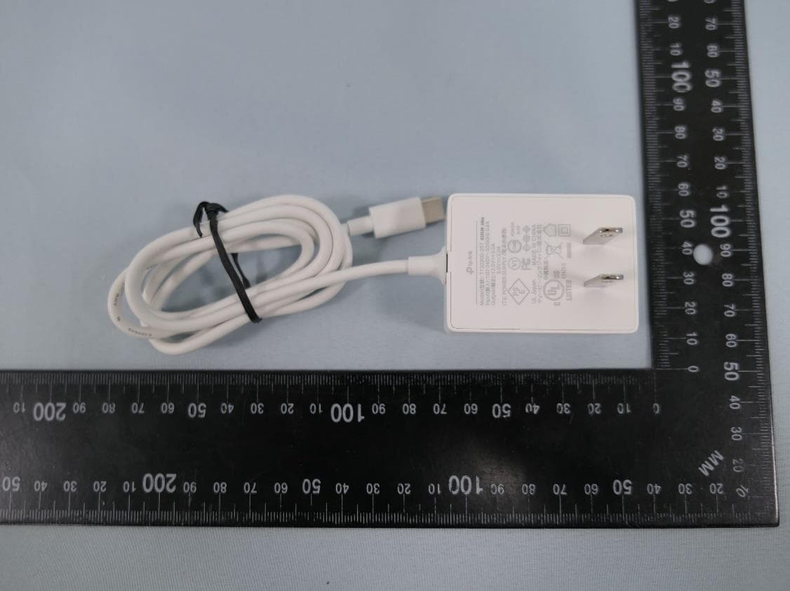
2AXJ4AIRE5
Jan 15, 2024AX3000 Wi-Fi 6 Air Range Extender
Equipment Class
DTS - Digital Transmission System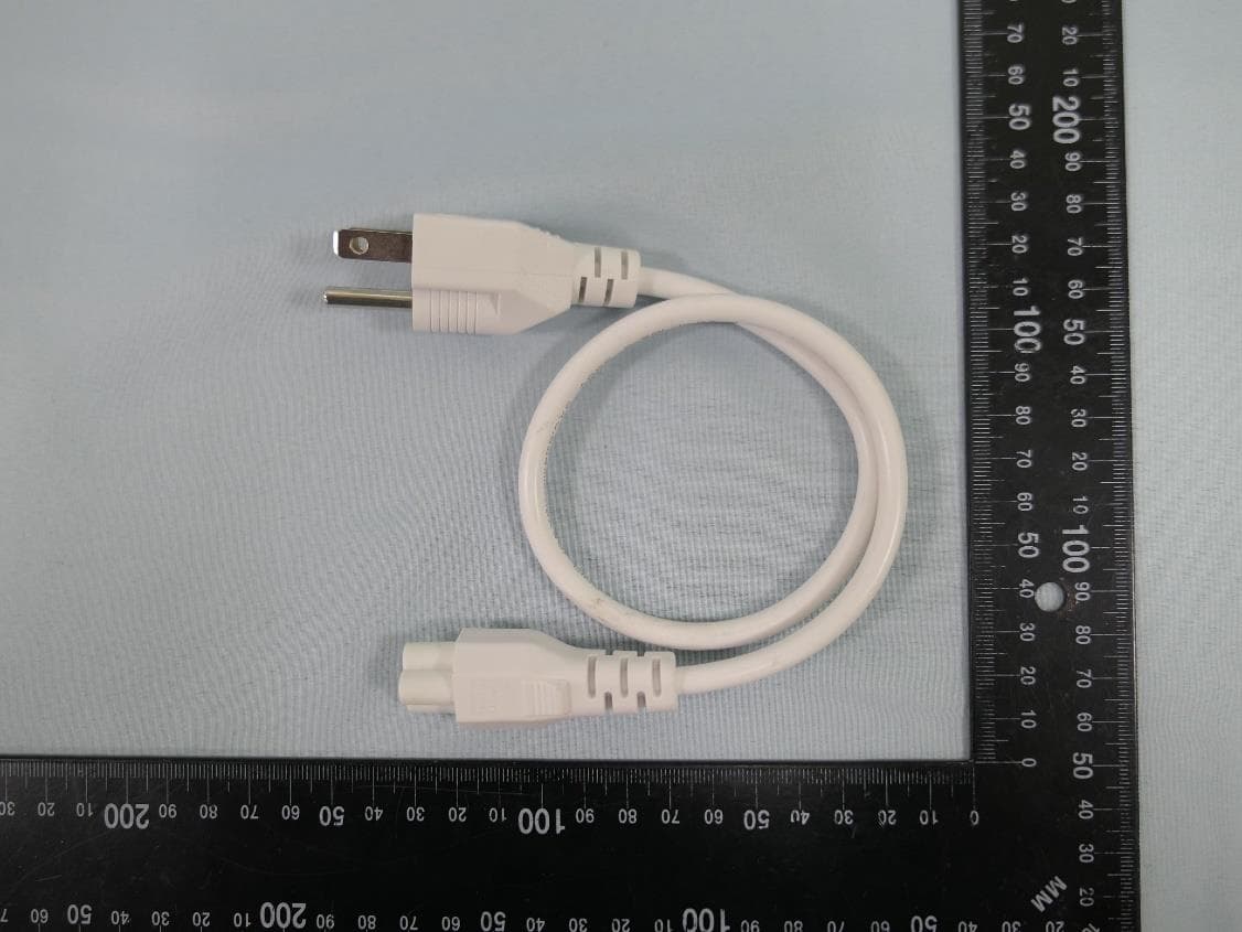
2AXJ4EAP115BRG
Jan 11, 20245GHz 300Mbps Long-range Indoor/Outdoor Access Point
Equipment Class
NII - Unlicensed National Information Infrastructure TX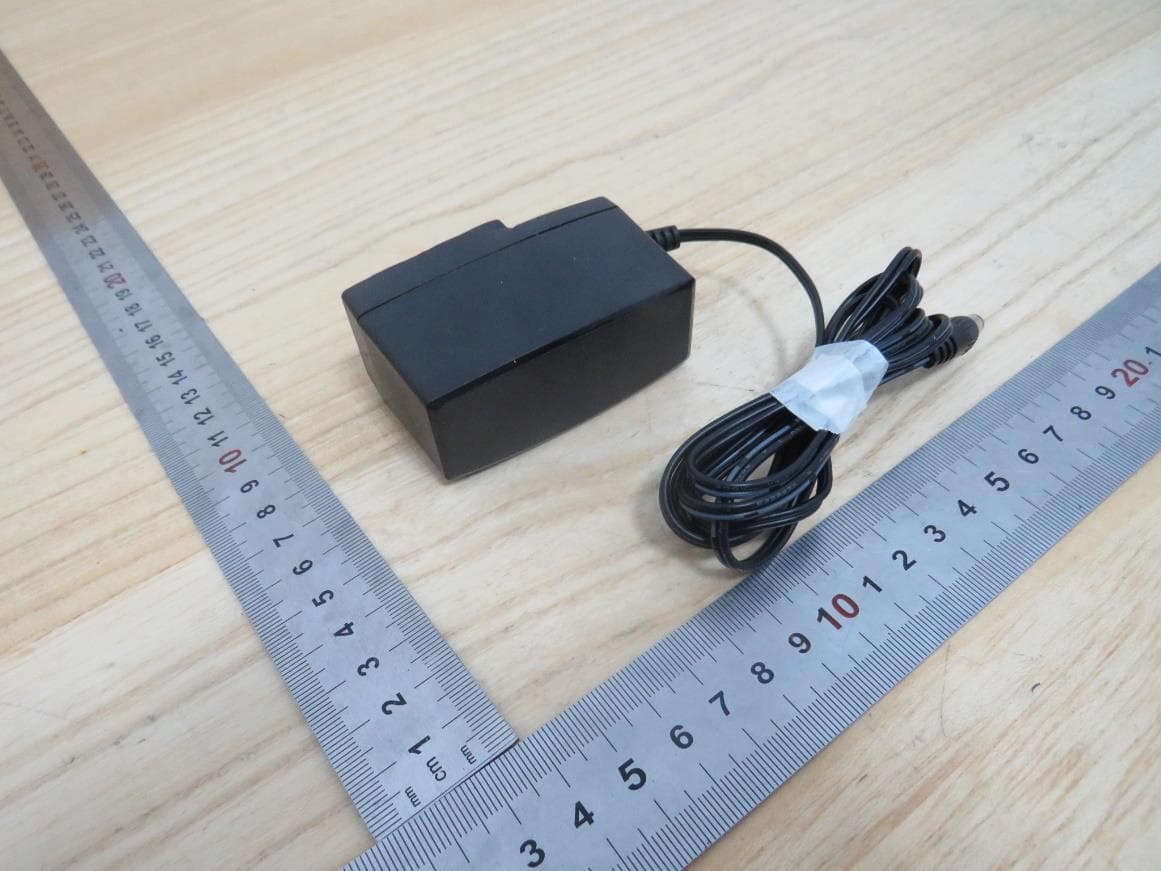
2AXJ4HX510V2
Jan 10, 2024AX3000 Whole Home Mesh Wi-Fi AP
Equipment Class
NII - Unlicensed National Information Infrastructure TX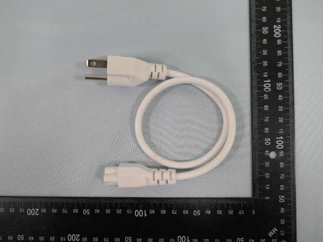
2AXJ4EAP215BRG
Dec 11, 20235GHz 867Mbps Long-range Indoor/Outdoor Access Point
Equipment Class
NII - Unlicensed National Information Infrastructure TX