2AXJ4EAP610ODAX1800 Indoor/Outdoor Wi-Fi 6 Access Point
TP-Link Corporation Limited
Click to zoom
Application Details
- Equipment Class
- DTS - Digital Transmission System
- Date of Grant
- Aug 24, 2021
- Application Purpose
- Original Equipment
- Date of Application
- Aug 24, 2021
- Equipment Note
- AX1800 Indoor/Outdoor Wi-Fi 6 Access Point
- Frequency Range
- 2412.00000000 - 2462.00000000
- Company
- TP-Link Corporation Limited
- Country
- Hong Kong
Documents & Files
Document Text
Text extracted from the exhibit documents filed with the FCC. Open a document above to read the original.
Users Manual
User Guide For TP-Link Omada Access Points 1910012995 REV4.7.0 March 2021 I CONTENTS About This User Guide........................................................................................................1 Overview .................................................................................................................................3 1 Quick Start .......................................................................................................................4 1.1 Determine the Management Method ..................................................................................................5 1.2 Connect Network Devices ......................................................................................................................6 1.3 Log in to the EAP and Change the SSID .............................................................................................8 1.4 Configure and Manage the EAP ..........................................................................................................21 2 Configure the Network ..............................................................................................22 2.1 Configure the Wireless Parameters ..................................................................................................23 2.1.1 Configure SSIDs ..............................................................................................................................24 2.1.2 Configure Wireless Advanced Settings .................................................................................30 Radio Setting ....................................................................................................................................30 Load Balance ....................................................................................................................................32 Airtime Fairness ..............................................................................................................................32 More Settings ..................................................................................................................................33 2.2 Configure Portal Authentication ........................................................................................................35 Configure Portal............................................................................................................................................36 Configure Free Authentication Policy ..................................................................................................42 2.3 Configure VLAN ........................................................................................................................................45 2.4 Configure MAC Filtering ........................................................................................................................46 2.5 Configure Scheduler ...............................................................................................................................49 2.6 Configure Band Steering .......................................................................................................................52 2.7 Configure QoS ...........................................................................................................................................54 2.8 Configure Rogue AP Detection ...........................................................................................................58 Detect Rogue APs and Move the Rogue APs to the Trusted AP List .......................................59 Manage the Trusted AP List .....................................................................................................................60 II 3 Monitor the Network ..................................................................................................62 3.1 Monitor the EAP ........................................................................................................................................63 3.2 Monitor the Wireless Parameters ......................................................................................................65 Monitor the SSIDs ........................................................................................................................................66 Monitor the Radio Settings .......................................................................................................................67 Monitor Radio Traffic ..................................................................................................................................67 Monitor LAN Traffic .....................................................................................................................................68 3.3 Monitor the Clients ..................................................................................................................................70 View Client Information ..............................................................................................................................70 View Block Client Information .................................................................................................................72 4 Manage the EAP ...........................................................................................................73 4.1 Manage the IP Address of the EAP ....................................................................................................74 4.2 Manage System Logs .............................................................................................................................77 View System Logs .......................................................................................................................................77 Configure the Way of Receiving Logs ..................................................................................................78 4.3 C…
Text truncated - open the document above for the full version.
Users Manual
Quick Installation Guide Setup with videos Visit https://www.tp-link.com/support/setup-video/ or scan the QR code to search for the setup video of your product model. Power LEDPoE Port Indoor/Outdoor Access Point Overview Package Contents Panel Layout © 2021 TP-Link 7106509165 REV1.0.0 Passive PoE Adapter LED Status Indication Solid green The device is initializing or working properly. Flashing yellow System errors. RAM, Flash, Ethernet, WLAN or firmware may be malfunctioning. Flashing yellow, green Firmware update is in progress. Do not disconnect or power off the device. Quickly flashing yellow, green The device is being reset to its factory default settings. Flashes green twice Initialization is completed. SYS LED Explanation Quickly flashing green Locate the device. Slowly flashing green The device is in an isolated state. 1 Lightning and ESD Protection Before mounting the EAP, you should consider Lightning and ESD Protection to ensure safety. Proper grounding is extremely important for outdoor devices. To reduce the damage of potential lightning and ESD attacks, connect the grounding terminal to grounding facilities using a proper grounding wire, which should meet the local installation requirements. You need to secure the grounding wire to the grounding terminal with the screw. Hardware Installation Mount the EAP The EAP can be pole-mounted or wall-mounted. Follow the steps below for the appropriate installation. Option 1: Pole Mounting Lead the end of the pole mounting strap through the back of the EAP. Step 1: Position the EAP and wrap the pole mounting strap around the pole. Feed the end through the screw-block and tighten the strap until the EAP is secure. Step 2: Option 2: Wall Mounting Step 1: Place the mounting bracket (for EAP) in the right position. Mark two positions for the screw holes . Drill two 6 mm holes for the screws at the marked positions. Step 2: Insert the plastic wall anchors into the 6 mm holes. Align the bracket (for EAP) to the plastic wall anchors and drive the self-tapping screws into the anchors through the bracket (for EAP). Step 3: Align the mounting tabs on the back of the EAP with the slot of the mounting bracket (for EAP). Push and slide the EAP downward until it locks into place. 3 Connect the Cable Fit an Ethernet cable through the Spiral Cover, Bracket, and O-Ring, and connect the cable to the port. Note: It’s recommended that you scan the QR code and watch the installation video. If you have any trouble in this process, please follow the instructions below step by step. Fit the O-Ring to the head of the Bracket and screw the Bracket to the body of the device. Note: Don’t warp the O-Ring. Fit the Ethernet cable through the Seal’s slit with the thicker side towards the Bracket, and plug the seal to the Bracket. Note: Choose the proper Seal according to the type and diameter of the Ethernet cable. Screw the Spiral Cover to the Bracket. RESETGrounding Terminal Ethernet Port LAN M3×28 Plastic Wall Anchors (Qty.4) M3×20 Self-tapping Screws (Qty.2) Mounting Bracket (for EAP) Pole Mounting Strap Mounting Kit M3×16 Self-tapping Screws (Qty.2) M3×6 Screw (For Securing the Grounding Wire) 2 1 2 3 4 LAN Port Passive PoE Adapter (Mounting Bracket Included) Power Cord Installation GuideEAP Spiral Cover O-Ring Bracket Waterproof Kit Seal (For Unshielded Cable) O-Ring Bracket EAP Grounded PoE Adapter Ethernet Cable Grounded 3-wire Power Outlet 1 3 4 2 Seal (For Shielded Cable) Spiral Cover Seal Option 2: Via PoE Switch PoE Switch Connect an Ethernet cable from the PoE switch to the Ethernet port. The PoE switch should comply with 802.3at. Power On The EAP can be powered via the provided passive PoE adapter or a PSE device (such as a PoE switch). Connect the EAP to a Power over Ethernet (PoE) adapter as follows: Option 1: Via Passive PoE Adapter Connecting the PoE Adapter PoELAN Ethernet cable length up to 100 m Mounting the PoE Adapter (Optional) Note: To ensure the passive PoE adapter is attached most securely, it is recommended to install the adapter with the Ethernet port facing upward. Step 1: Remove the mounting bracket from the passive PoE Adapter. Drill two holes on the wall and insert the plastic wall anchors into the the holes. Secure the mounting bracket to the wall. Make sure the shoulders at the corners of the mounting bracket are on the outside and pointing upward. Step 2: Attach the passive PoE adapter to the mounting bracket (for PoE Adapter) by sliding the adapter in the direction of the arrows until it locks into place. Attention: In EU member states, EFTA countries and Northern Ireland, the operation in the frequency range 5150MHz-5350MHz is only permitted indoors. Attention: In Great Britain, the operation in the frequency range 5150MHz - 5350MHz is only permitted indoors. For EAP Controller, go to Access Point page and select the desired EAP to specify the channel. For web browser, go to Wireless > Wireless Settings to specify the channel. For detailed configurations, please visit https://www.tp-link.com/support to download the User Guide of EAP in the download center. For technical support, the user guide and other information, please visit https://www.tp-link.com/support, or simply scan the QR code. If you have any suggestions or needs on the product guides, welcome to email [email protected]. To ask questions, find answers, and communicate with TP-Link users or engineers, please visit https://community.tp-link.com to join TP-Link Community. The products of TP-Link partly contain software code developed by third parties, including software code subject to the GNU General Public License (“GPL”). As applicable, the terms of the GPL and any information on obtaining access to the respective GPL Code used in TP-Link products are available to you in GPL-Code-Centre under (https://www.tp-link.com/en/support/gpl/). The respective programs are distributed WITHOUT ANY WARRANTY and are subject to the copyrights of one or more authors. For det…
Text truncated - open the document above for the full version.
Users Manual
Regulatory Compliance Outdoor EAP For Class A Outdoor EAP with adapter: FCC Compliance Information Statement Product Name: Omada Outdoor Access Point Model Number: EAP110-Outdoor Component NameModel I.T.E. Power SupplyTL-POE2406 (EAP110-Outdoor) Responsible party: TP-Link USA Corporation, d/b/a TP-Link North America, Inc. Address: 145 South State College Blvd. Suite 400, Brea, CA 92821 Website: https://www.tp-link.com/us/ Tel: +1 626 333 0234 Fax: +1 909 527 6803 E-mail: [email protected] This equipment has been tested and found to comply with the limits for a Class A digital device, pursuant to part 15 of the FCC Rules. These limits are designed to provide reasonable protection against harmful interference when the equipment is operated in a commercial environment. This equipment generates, uses, and can radiate radio frequency energy and, if not installed and used in accordance with the instruction manual, may cause harmful interference to radio communications. Operation of this equipment in a residential area is likely to cause harmful interference in which case the user will be required to correct the interference at his own expense. This device complies with part 15 of the FCC Rules. Operation is subject to the following two conditions: 1) This device may not cause harmful interference. 2) This device must accept any interference received, including interference that may cause undesired operation. Any changes or modifications not expressly approved by the party responsible for compliance could void the user’s authority to operate the equipment. Note: The manufacturer is not responsible for any radio or TV interference caused by unauthorized modifications to this equipment. Such modifications could void the user’s authority to operate the equipment. FCC RF Radiation Exposure Statement: This equipment complies with FCC RF radiation exposure limits set forth for an uncontrolled environment. This device and its antenna must not be co-located or operating in conjunction with any other antenna or transmitter. “To comply with FCC RF exposure compliance requirements, this grant is applicable to only Mobile Configurations. The antennas used for this transmitter must be installed to provide a separation distance of at least 20cm from all persons and must not be colocated or operating in conjunction with any other antenna or transmitter.” Product Name: I.T.E. Power Supply Model Number: TL-POE2406 Responsible party: TP-Link USA Corporation, d/b/a TP-Link North America, Inc. Address: 145 South State College Blvd. Suite 400, Brea, CA 92821 Website: https://www.tp-link.com/us/ Tel: +1 626 333 0234 Fax: +1 909 527 6803 E-mail: [email protected] This equipment has been tested and found to comply with the limits for a Class B digital device, pursuant to part 15 of the FCC Rules. These limits are designed to provide reasonable protection against harmful interference in a residential installation. This equipment generates, uses and can radiate radio frequency energy and, if not installed and used in accordance with the instructions, may cause harmful interference to radio communications. However, there is no guarantee that interference will not occur in a particular installation. If this equipment does cause harmful interference to radio or television reception, which can be determined by turning the equipment off and on, the user is encouraged to try to correct the interference by one or more of the following measures: •Reorient or relocate the receiving antenna. • Increase the separation between the equipment and receiver. •Connect the equipment into an outlet on a circuit different from that to which the receiver is connected. •Consult the dealer or an experienced radio/ TV technician for help. This device complies with part 15 of the FCC Rules. Operation is subject to the following two conditions: 1) This device may not cause harmful interference. 2) This device must accept any interference received, including interference that may cause undesired operation. Any changes or modifications not expressly approved by the party responsible for compliance could void the user’s authority to operate the equipment. We, TP-Link USA Corporation, has determined that the equipment shown as above has been shown to comply with the applicable technical standards, FCC part 15. There is no unauthorized change is made in the equipment and the equipment is properly maintained and operated. Issue Date:2020-5-12 CE Mark Warning This is a class A product. In a domestic environment, this product may cause radio interference, in which case the user may be required to take adequate measures. OPERATING FREQUENCY (the maximum transmitted power) 2412MHz—2472MHz(20dBm) EU declaration of conformity TP-Link hereby declares that the device is in compliance with the essential requirements and other relevant provisions of directives 2014/53/EU, 2009/125/EC, 2011/65/EU and (EU)2015/863. The original EU declaration of conformity may be found at https://www.tp-link.com/en/ce. RF Exposure Information This device meets the EU requirements (2014/53/EU Article 3.1a) on the limitation of exposure of the general public to electromagnetic fields by way of health protection. The device complies with RF specifications when the device used at 20 cm from your body. Canadian Compliance Statement This device contains licence-exempt transmitter(s)/receiver(s) that comply with Innovation, Science and Economic Development Canada’s licence-exempt RSS(s). Operation is subject to the following two conditions: (1) This device may not cause interference. (2) This device must accept any interference, including interference that may cause undesired operation of the device. L’émetteur/récepteur exempt de licence contenu dans le présent appareil est conforme aux CNR d’Innovation, Sciences et Développement économique Canada applicables aux appareils radio exempts de licence. L’exploitation est autorisée aux deux conditions suivantes : 1) L’appareil ne do…
Text truncated - open the document above for the full version.
Cover Letter(s)
TP-Link Corporation Limited Authority to Act as Agent Date: 2021-08-13 American Certification Body, Inc. 6731 Whittier Avenue Suite C110 McLean, VA 22101 To Whom It May Concern: BTL Inc./Rose Liu is authorized to act on our behalf, until otherwise notified, for applications to American Certification Body, Inc. (ACB). We certify that we are not subject to denial of federal benefits, that includes FCC benefits, pursuant to Section 5301 of the Anti-Drug Abuse Act of 1988, 21 U.S.C. 862. Further, no party, as defined in 47 CFR 1.2002 (b), to the application is subject to denial of federal benefits, that includes FCC benefits. Thank you, Agency Agreement Expiration Date: 2022-08-13 By: __________________________ _______Abby Liang________ (Signature 1 ) (Print name) Title: Regulatory Compliance Manager On behalf of: TP-Link Corporation Limited (Company Name) Telephone: 00852-37585503 1 - Must be signed by applicant contact given for applicant on the FCC site, or by the authorized agent if an appropriate authorized agent letter has been provided. Letters should be placed on appropriate letterhead.
Cover Letter(s)
TP-Link Corporation Limited Request for Confidentiality Date: 2021-08-13 Subject: Confidentiality Request for: 2AXJ4EAP610OD Pursuant to FCC 47 CRF 0.457(d) and 0.459 and IC RSP-100, Section12.4, the applicant requests that a part of the subject FCC application be held confidential. Type of Confidentiality Requested Exhibit Short Term Permanent Block Diagrams Short Term External Photos Short Term Permanent* 1 Internal Photos Short Term Permanent Operation Description/Theory of Operation Short Term Permanent Parts List & Placement/BOM Short Term Permanent Tune-Up Procedure Short Term Permanent Schematics Short Term Test Setup Photos Short Term Permanent* 3 User’s Manual TP-Link Corporation Limited____ has spent substantial effort in developing this product and it is one of the first of its kind in industry. Having the subject information easily available to "competition" would negate the advantage they have achieved by developing this product. Not protecting the details of the design will result in financial hardship. Permanent Confidentiality: The applicant requests the exhibits listed above as permanently confidential be permanently withheld from public review due to materials that contain trade secrets and proprietary information not customarily released to the public. Short-Term Confidentiality: The applicant requests the exhibits selected above as short term confidential be withheld from public view for a period of ___(specify number of days not to exceed 180) 2 ___ days from the date of the Grant of Equipment Authorization and prior to marketing. This is to avoid premature release of sensitive information prior to marketing or release of the product to the public. Applicant is also aware that they are responsible to notify ACB in the event information regarding the product or the product is made available to the public. ACB will then release the documents listed above for public disclosure pursuant to FCC Public Notice DA 04-1705. NOTE for Industry Canada Applications: IC currently only distinguishes Permanent Confidentiality exhibits as shown above. Short Term confidentiality is not considered applicable to IC applications. Sincerely, By: Regulatory Compliance Manager _Abby Liang__________ (Signature/Title 3 ) (Print name) 1 - The asterisked items (*) require further information to be provided to ACB before permanent confidentiality will be extended to these exhibits. Please refer to FCC KDB 726920 and the specific Document link for D01 found at: https://apps.fcc.gov/oetcf/kdb/forms/FTSSearchResultPage.cfm?switch=P&id=41731 and review section II, 3) regarding specific information that must accompany these requests. 2 - Please refer to http://acbcert.com/documents/misc-docs/Memo-Short-Term-Vs-Standard-Confidentiality.pdf for complete details. 3 - Must be signed by applicant contact given for applicant on the FCC site, or by the authorized agent if an appropriate authorized agent letter has been provided. Letters should be placed on appropriate letterhead.
Cover Letter(s)
TP-Link Corporation Limited Wi-Fi Channel 12 and 13 Declaration Letter Date: 2021-08-13 We, the undersigned company Company Name: TP-Link Corporation Limited Address: Room 901, 9/F. , New East Ocean Centre, 9 Science Museum Road, Tsim Sha Tsui, Kowloon,Hong Kong Declare that: Product description: AX1800 Indoor/Outdoor Wi-Fi 6 Access Point Type designation: EAP610-Outdoor Brand: tp-link FCC ID: 2AXJ4EAP610OD Only channels 1~11 will be used in USA. Country code selection is disabled. If you have any questions regarding the authorization, please do not hesitate to contact us, thank you~ Sincerely, Signature: ________________________ Name: Abby Liang Tel: 00852-37585503 Email: [email protected]
External Photos
Report No.: 2101C073A Page 1 of 13 ATTACHMENT PHOTOGRAPHS OF EUT Report No.: 2101C073A Page 2 of 13 Report No.: 2101C073A Page 3 of 13 Report No.: 2101C073A Page 4 of 13 Report No.: 2101C073A Page 5 of 13 Report No.: 2101C073A Page 6 of 13 Report No.: 2101C073A Page 7 of 13
ID Label/Location Info
A2 姚远 调整排版 2021-01-27 EAP610-Outdoor 1.0壳体镭雕 EAP610-Outdoor 1.0 尺寸:71.12*32.49mm 颜色:Pantone Cool Gray 6C 注:机型版本, SN码根据实际情况生成。 MAC条码由“XXXXXXXXXXXX”生成, 文本打印为“XX-XX-XX-XX-XX-XX”。 SSID以软件生成工具为准 EAP610-Outdoor AX1800 Indoor/Outdoor Wi-Fi 6 Access Point Model: EAP610-Outdoor Power: 48V0.5A 802.3at PoE: 42-57V0.6A 201-210017 IEEE802.11b/g/n/ax IEEE802.11a/n/ac/ax W52W53W56 This device complies with part 15 of the FCC Rules. Operation is subject to the following two conditions:(1) This device may not cause harmful interference, and (2) this device must accept any interference received, including interference that may cause undesired operation. TP-Link Corporation Limited Suite 901, New East Ocean Centre, Tsim Sha Tsui, Hong Kong IC: 26583-EAP610OD FCC ID: 2AXJ4EAP610OD MAC: XX-XX-XX-XX-XX-XX SSID: TP-Link_2.4GHz_XXXXXX SSID: TP-Link_5GHz_XXXXXX Model: EAP610-Outdoor(US) Ver:1.0 S/N: XXXXXXXXXXXXX 10±0.3mm 32.49 71.12 15.32±0.3mm
Internal Photos
Report No.: 2101C073A Page 8 of 13 Report No.: 2101C073A Page 9 of 13 Ant. 1 Ant. 2 Report No.: 2101C073A Page 10 of 13 Report No.: 2101C073A Page 11 of 13 Report No.: 2101C073A Page 12 of 13 Report No.: 2101C073A Page 13 of 13
RF Exposure Info
Report No.: BTL-FCCP-3-2101C073A Page 1 of 6 FCC RF EXPOSURE REPORT FCC ID: 2AXJ4EAP610OD Project No. : 2101C073A Equipment : AX1800 Indoor/Outdoor Wi-Fi 6 Access Point Brand Name : tp-link Test Model : EAP610-Outdoor Series Model : N/A Applicant : TP-Link Corporation Limited Address : Room 901, 9/F. , New East Ocean Centre, 9 Science Museum Road, Tsim Sha Tsui, Kowloon, Hong Kong Manufacturer : TP-Link Corporation Limited Address : Room 901, 9/F. , New East Ocean Centre, 9 Science Museum Road, Tsim Sha Tsui, Kowloon, Hong Kong Date of Receipt : Mar. 04, 2021 Date of Test : Apr. 12, 2021 ~ Jul. 22, 2021 Issued Date : Aug. 13, 2021 Report Version : R00 Test Sample : Engineering Sample No.: DG202105205 Standard(s) : FCC Guidelines for Human Exposure IEEE C95.1 & FCC Part 2.1091 FCC Title 47 Part 2.1091, OET Bulletin 65 Supplement C The above equipment has been tested and found compliance with the requirement of the relative standards by BTL Inc. Prepared by : Sheldon Ou Approved by : Ethan Ma Add: No. 3 Jinshagang 1st Rd. Shixia, Dalang Town, Dongguan City, Guangdong, People’s Republic of China Te l : +86-769-8318-3000 Web: www.newbtl.com Report No.: BTL-FCCP-3-2101C073A Page 2 of 6 REPORT ISSUED HISTORY Report Version Description Issued Date R00 Original Issue Aug. 13, 2021 Report No.: BTL-FCCP-3-2101C073A Page 3 of 6 1. TEST FACILITY The test facilities used to collect the test data in this report is at the location of No. 3 Jinshagang 1st Rd. Shixia, Dalang Town, Dongguan City, Guangdong, People’s Republic of China. BTL's Test Firm Registration Number for FCC: 357015 BTL's Designation Number for FCC: CN1240 2. MPE CALCULATION METHOD Calculation Method of RF Safety Distance: where: S = power density P = power input to the antenna G = power gain of the antenna in the direction of interest relative to an isotropic radiator R = distance to the center of radiation of the antenna Antenna Specification: For 2.4GHz: Ant. Brand P/N Antenna Type Connector Gain (dBi) 1 tp -link EAP610-Outdoor 1.0 Internal N/A 4.53 2 tp -link EAP610-Outdoor 1.0 Internal N/A 4.48 Note: 1) This EUT supports CDD, and all antenna gains are not equal, Directional gain=10log[(10 G1/20 +10 G2/20 +...10 GN/20 ) 2 /N]dBi, that is Directional gain=10log[(10 4.53/20 +10 4.48/20 ) 2 /2]dBi =7.52. So, the output power limit is 30-(7.52-6)=28.48, the power spectral density limit is 8-(7.52-6)=6.48. 2) Beamforming Gain: 3 dB. Then, Directional gain=3+4.53=7.53. So the output power limit is 30-(7.53-6)=28.47. 3) The antenna gain and beamforming gain are provided by the manufacturer. For 5GHz: Ant. Brand P/N Antenna Type Connector Gain (dBi) Note 1 tp -link EAP610-Outdoor 1.0 Internal N/A 4.53 UNII-1 2 tp -link EAP610-Outdoor 1.0 Internal N/A 4.14 1 tp -link EAP610-Outdoor 1.0 Internal N/A 4.95 UNII-3 2 tp -link EAP610-Outdoor 1.0 Internal N/A 5.04 Note: 1) This EUT supports CDD, and all antenna gains are not equal, Directional gain=10log[(10 G1/20 +10 G2/20 +...10 GN/20 ) 2 /N]dBi. Then, For UNII-1: Directional gain=10log[(10 4.53/20 +10 4.14/20 ) 2 /2]dBi =7.35. So, the output power limit is 30-(7.35-6)=28.65, the power spectral density limit is 17-(7.35-6)=15.65. For UNII-3: Directional gain=10log[(10 4.95/20 +10 5.04/20 ) 2 /2]dBi =8.01. So, the output power limit is 30-(8.01-6)=27.99, the power spectral density limit is 30-(8.01-6)=27.99. 2) Beamforming Gain: 3 dB. Then, For UNII-1: Directional gain=3+4.53=7.53. So the output power limit is 30-(7.53-6)=28.47. For UNII-3: Directional gain=3+5.04=8.04. So the output power limit is 30-(8.04-6)=27.96. 3) The antenna gain and beamforming gain are provided by the manufacturer. Report No.: BTL-FCCP-3-2101C073A Page 4 of 6 Table for Antenna Configuration: For 2.4GHz Non Beamforming: Operating Mode TX Mode 2TX IEEE 802.11b V (Ant. 1+Ant. 2) IEEE 802.11g V (Ant. 1+Ant. 2) IEEE 802.11n(HT20) V (Ant. 1+Ant. 2) IEEE 802.11n(HT40) V (Ant. 1+Ant. 2) IEEE 802.11ax(HE20) V (Ant. 1+Ant. 2) IEEE 802.11ax(HE40) V (Ant. 1+Ant. 2) For 2.4GHz Beamforming: Operating Mode TX Mode 2TX IEEE 802.11n(HT20) V (Ant. 1+Ant. 2) IEEE 802.11n(HT40) V (Ant. 1+Ant. 2) IEEE 802.11ax(HE20) V (Ant. 1+Ant. 2) IEEE 802.11ax(HE40) V (Ant. 1+Ant. 2) For 5GHz Non Beamforming: Operating Mode TX Mode 2TX IEEE 802.11a V (Ant. 1+Ant. 2) IEEE 802.11n(HT20) V (Ant. 1+Ant. 2) IEEE 802.11n(HT40) V (Ant. 1+Ant. 2) IEEE 802.11ac(VHT20) V (Ant. 1+Ant. 2) IEEE 802.11ac(VHT40) V (Ant. 1+Ant. 2) IEEE 802.11ac(VHT80) V (Ant. 1+Ant. 2) IEEE 802.11ax(HE20) V (Ant. 1+Ant. 2) IEEE 802.11ax(HE40) V (Ant. 1+Ant. 2) IEEE 802.11ax(HE80) V (Ant. 1+Ant. 2) Report No.: BTL-FCCP-3-2101C073A Page 5 of 6 For 5GHz Beamforming: Operating Mode TX Mode 2TX IEEE 802.11n(HT20) V (Ant. 1+Ant. 2) IEEE 802.11n(HT40) V (Ant. 1+Ant. 2) IEEE 802.11ac(VHT20) V (Ant. 1+Ant. 2) IEEE 802.11ac(VHT40) V (Ant. 1+Ant. 2) IEEE 802.11ac(VHT80) V (Ant. 1+Ant. 2) IEEE 802.11ax(HE20) V (Ant. 1+Ant. 2) IEEE 802.11ax(HE40) V (Ant. 1+Ant. 2) IEEE 802.11ax(HE80) V (Ant. 1+Ant. 2) Report No.: BTL-FCCP-3-2101C073A Page 6 of 6 3. TEST RESULTS For 2.4GHz Non Beamforming: Directional Gain (dBi) Directional Gain (numeric) Max. Average Output Power (dBm) Max. Average Output Power (mW) Power Density (S) (mW/cm 2 ) Limit of Power Density (S) (mW/cm 2 ) Test Result 7.52 5.6494 27.73 592.9253 0.42671 1 Complies For 2.4GHz Beamforming: Directional Gain (dBi) Directional Gain (numeric) Max. Average Output Power (dBm) Max. Average Output Power (mW) Power Density (S) (mW/cm 2 ) Limit of Power Density (S) (mW/cm 2 ) Test Result 7.53 5.6624 27.08 510.5050 0.36824 1 Complies For 5GHz Non Beamforming: Directional Gain (dBi) Directional Gain (numeric) Max. Output Power (dBm) Max. Output Power (mW) Power Density (S) (mW/cm 2 ) Limit of Powe…
Text truncated - open the document above for the full version.
Contact Information
Applicant
Sarah Wang
Technical Contact
BTL Inc.Steven Lu
[email protected]86-769-83183000
No.3 Jinshagang 1st Rd, Shixia, Dalang · Dongguan City · China
Non-Technical Contact
BTL Inc.Rose Liu
[email protected]86-769-83183000
Test Firm
BTL Inc.Sophia Huang
[email protected]+86-769-83183000
Technical Specifications
| # | Rule Parts | Frequency Range | Power Output |
|---|---|---|---|
| 1 | 15C | 2.41 GHz - 2.46 GHz | 566.20 mW |
Other Applications from TP-Link Corporation Limited
2AXJ4TXE50UH
Jan 28, 2024AXE3000 Wi-Fi 6E High Gain Wireless USB Adapter
Equipment Class
NII - Unlicensed National Information Infrastructure TX
2AXJ4AIRE5
Jan 15, 2024AX3000 Wi-Fi 6 Air Range Extender
Equipment Class
DTS - Digital Transmission System
2AXJ4EAP115BRG
Jan 11, 20245GHz 300Mbps Long-range Indoor/Outdoor Access Point
Equipment Class
NII - Unlicensed National Information Infrastructure TX
2AXJ4HX510V2
Jan 10, 2024AX3000 Whole Home Mesh Wi-Fi AP
Equipment Class
NII - Unlicensed National Information Infrastructure TX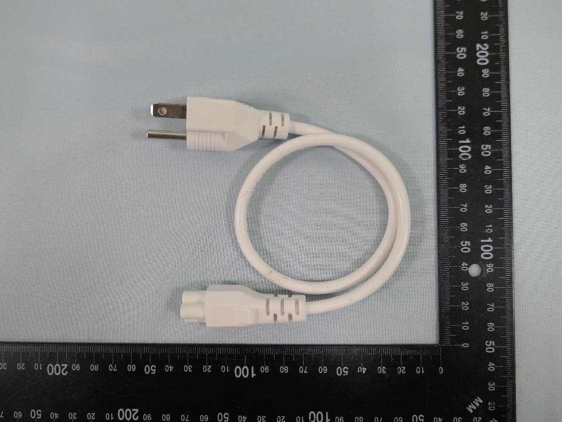
2AXJ4EAP215BRG
Dec 11, 20235GHz 867Mbps Long-range Indoor/Outdoor Access Point
Equipment Class
NII - Unlicensed National Information Infrastructure TX