2AXJ4EAP650V2AX3000 Ceiling Mount Wi-Fi 6 Access Point
TP-Link Corporation Limited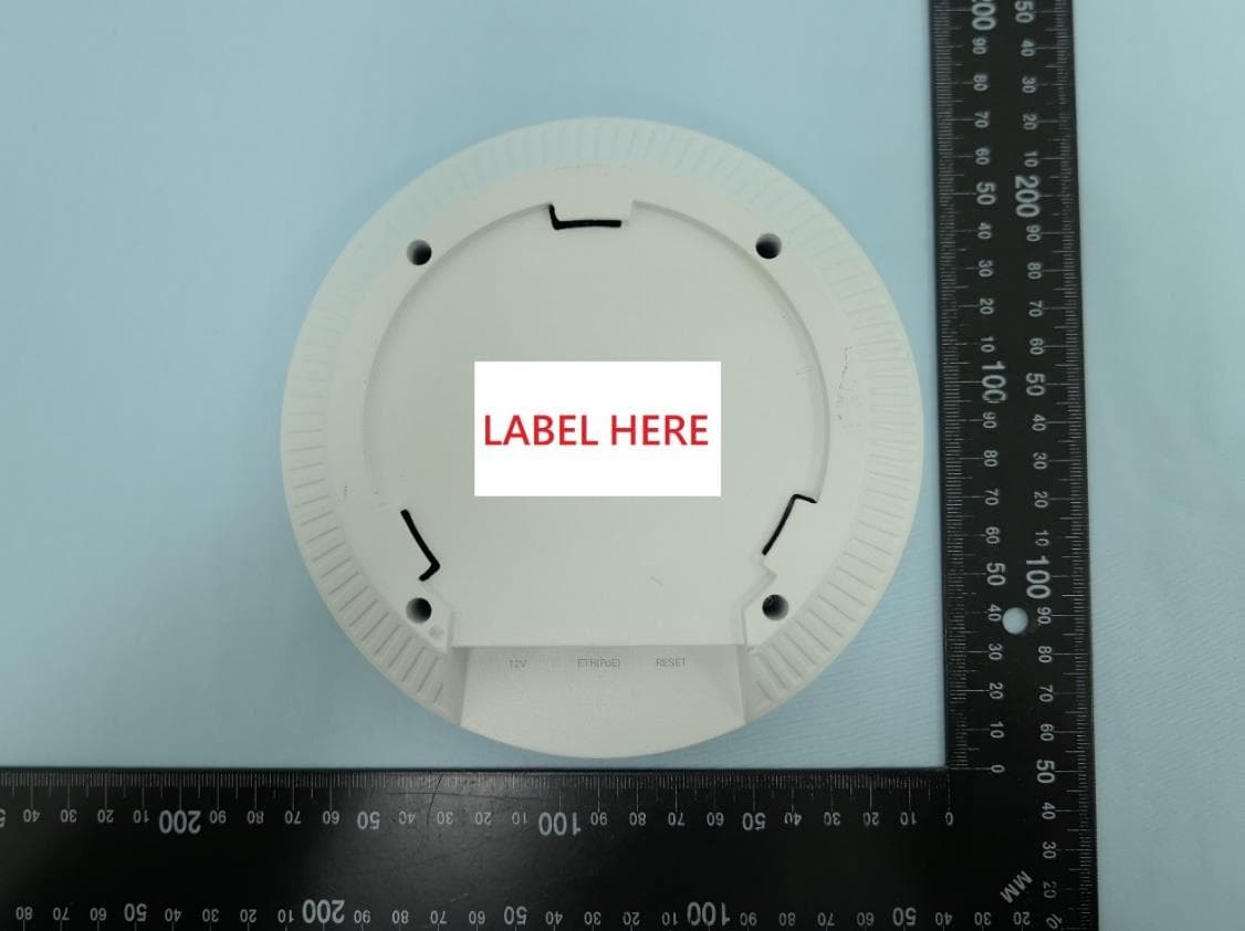
Click to zoom
Application Details
- Equipment Class
- DTS - Digital Transmission System
- Date of Grant
- Jul 27, 2023
- Application Purpose
- Original Equipment
- Date of Application
- Jul 15, 2023
- Equipment Note
- AX3000 Ceiling Mount Wi-Fi 6 Access Point
- Frequency Range
- 2412.00000000 - 2462.00000000
- Company
- TP-Link Corporation Limited
- Country
- Hong Kong
Documents & Files
Document Text
Text extracted from the exhibit documents filed with the FCC. Open a document above to read the original.
Users Manual
Quick Installation Guide Wireless Access Point Setup with videos Visit https://www.tp-link.com/support/setup-video/ or scan the QR code to search for the setup video of your product model. Note: For simplicity, we will take EAP650 V1 for example throughout the Guide. The image may differ from the actual product. Hardware Overview 1 On: Working normally/Initializing. Off: Working abnormally/Power off/LED is turned off. Flashing: Initialization: The LED flashes twice after initialization is completed. Upgrade: The LED flashes once per second while upgrading. Reset: The LED flashes quickly during the reset. The EAP will then reboot. Isolated: The LED flashes slowly. The EAP is in the isolated state. Locate: When the Locate feature is activated in the Omada controller, the LED flashes quickly to locate and identify the device. The LED will flash for 10 minutes, or you can disable the feature manually to stop it flashing. LED Indicator RESET With the device powered on, press and hold the button for about 5 seconds until the LED flashes quickly. Then release the button. The device will restore to factory default settings. The port is used to connect to a router or a switch to transmit data, or to a PSE (Power Sourcing Equipment), such as a PoE switch, for both data transmission and Power over Ethernet (PoE) through Ethernet cable. The port supports transmission speed of 10/100/1000 Mbps. Ethernet Port: ETH (PoE) Plug one end of the provided power adapter to this port and the other end to a standard electrical wall outlet to power the EAP. Please use the power adapter provided in the package. Power Port M3×20 Self-tapping Screws (Qty.4) M3×28 Plastic Wall Anchors (Qty.4) 1 Remove the ceiling tile. Note: Make sure that the ceiling tile is larger than the EAP. Wing Nuts (Qty.4)Washers (Qty.4)M3×30 Pan-head Screws (Qty.4) The EAP can be mounted to the ceiling, the wall, or in a junction box, using the screws in the package. Choose the appropriate mounting and installation steps below. Note: This product requires heat dissipation through the metal bracket during use, please be careful not to touch the metal bracket in the heat dissipation. Hardware Installation 2 2 Insert the plastic wall anchors into the 6 mm diameter holes. 4 Connect the Ethernet cable to the Ethernet port on the EAP. Front Panel Rear Panel Option 2: Wall Mounting Option 1: Ceiling Mounting Option 2: Wall Mounting 5 Connect the Ethernet cable to the Ethernet port. Please pay attention to the triangle sign. Attach the EAP to the mounting bracket, then rotate it until it locks into place, as shown on the left. 2 Place the mounting bracket in the center of the ceiling tile. Mark four positions for the screw holes and a location for the Ethernet cable hole. Drill four 4 mm (5/32 in) diameter holes for the screws and a 25 mm (63/64 in) diameter hole for the Ethernet cable at the marked positions. Drill Hole for Ethernet cable X4 3 Secure the mounting bracket to the ceiling tile using four M3x30 pan-head screws, washers, and wing nuts, as shown on the left. 5 Attach the EAP to the mounting bracket by rotating it until it locks into place, as shown on the left. Option 3: Junction Box Mounting 4 Feed the Ethernet cable through the hole and set the ceiling tile back into place. Prepare the cables and the junction box in advance. Ensure that the mounting holes align to your junction box. *Compatible wall junctions: Route the cables through the square cable hole on the mounting bracket, and secure the mounting bracket to the junction box using screws. Then follow Step 4 and Step 5 of Option 2 to complete the installation. 3 Secure the mounting bracket to the wall by driving the self-tapping screws into the anchors. Make sure that the shoulders of the mounting bracket are on the outside. 1 If your Ethernet cable feeds through the wall, position the mounting bracket below the cable hole. Mark four positions for the screw holes and drill four 6 mm (15/64 in) diameter holes at the marked positions. X4 Option 1: Ceiling Mounting Option 3: Junction Box Mounting ©2022 TP-Link 7106509871 REV1.1.0 The products of TP-Link partly contain software code developed by third parties, including software code subject to the GNU General Public License (“GPL”). As applicable, the terms of the GPL and any information on obtaining access to the respective GPL Code used in TP-Link products are available to you in GPL-Code-Centre under (https://www.tp-link.com/en/support/gpl/). The respective programs are distributed WITHOUT ANY WARRANTY and are subject to the copyrights of one or more authors. For details, see the GPL Code and other terms of the GPL. Choose from the following methods to set up your EAPs: The EAP can be powered via a power adapter or a PSE device (such as a PoE switch) which complies with Power Source Class 2 ( PS2) or Limited Power Source (LPS) of IEC 62368-1. Method 1: Standalone Mode Option 1: Via PoE Switch (Compliant with 802.3at) Option 2: Via Power Adapter Note: Via Omada App Via Omada App 1. Connect wirelessly by using the default SSID (format: TP-Link_2.4GHz/5GHz_XXXXXX) printed on the label at the bottom of the product. 2. Launch a web browser and enter http://tplinkeap.net in the address bar. Use admin for both Username and Password to log in. 3. Set up a new Username and Password for secure management purpose. Modify the wireless parameters and reconnect your wireless devices to the new wireless network. To configure other EAPs, connect your device to the EAP by the corresponding default SSID and repeat the steps listed above. You can configure some basic functions in Standalone Mode. If you want to configure advanced functions, use Controller Mode. 1. Download the TP-Link Omada App on your mobile device. It can be downloaded from App Store or Google Play: 2. Connect your mobile device to the EAP by using the default SSID (format: TP-Link_2.4GHz/5GHz_XXXXXX) printed on the label at the bottom of the product. 3. Open the Omada App, and …
Text truncated - open the document above for the full version.
Users Manual
Regulatory Compliance Ceiling Mount EAP For Class A Ceiling Mount EAP with adapter: FCC Compliance Information Statement Product Name: Omada Ceiling Mount Access Point Model Number: EAP660 HD Component NameModel I.T.E. Power SupplyT120200-2B1 (For EAP660 HD) Responsible party: TP-Link USA Corporation Address: 10 Mauchly, Irvine, CA 92618 Website: https://www.tp-link.com/us/ Tel: +1 626 333 0234 Fax: +1 909 527 6804 E-mail: [email protected] This equipment has been tested and found to comply with the limits for a Class A digital device, pursuant to part 15 of the FCC Rules. These limits are designed to provide reasonable protection against harmful interference when the equipment is operated in a commercial environment. This equipment generates, uses, and can radiate radio frequency energy and, if not installed and used in accordance with the instruction manual, may cause harmful interference to radio communications. Operation of this equipment in a residential area is likely to cause harmful interference in which case the user will be required to correct the interference at his own expense. This device complies with part 15 of the FCC Rules. Operation is subject to the following two conditions: 1) This device may not cause harmful interference. 2) This device must accept any interference received, including interference that may cause undesired operation. Any changes or modifications not expressly approved by the party responsible for compliance could void the user’s authority to operate the equipment. Note: The manufacturer is not responsible for any radio or TV interference caused by unauthorized modifications to this equipment. Such modifications could void the user’s authority to operate the equipment. FCC RF Radiation Exposure Statement: This equipment complies with FCC RF radiation exposure limits set forth for an uncontrolled environment. This device and its antenna must not be co-located or operating in conjunction with any other antenna or transmitter. “To comply with FCC RF exposure compliance requirements, this grant is applicable to only Mobile Configurations. The antennas used for this transmitter must be installed to provide a separation distance of at least 20cm from all persons and must not be colocated or operating in conjunction with any other antenna or transmitter.” Product Name: I.T.E. Power Supply Model Number: T120200-2B1 Responsible party: TP-Link USA Corporation Address: 10 Mauchly, Irvine, CA 92618 Website: https://www.tp-link.com/us/ Tel: +1 626 333 0234 Fax: +1 909 527 6804 E-mail: [email protected] This equipment has been tested and found to comply with the limits for a Class B digital device, pursuant to part 15 of the FCC Rules. These limits are designed to provide reasonable protection against harmful interference in a residential installation. This equipment generates, uses and can radiate radio frequency energy and, if not installed and used in accordance with the instructions, may cause harmful interference to radio communications. However, there is no guarantee that interference will not occur in a particular installation. If this equipment does cause harmful interference to radio or television reception, which can be determined by turning the equipment off and on, the user is encouraged to try to correct the interference by one or more of the following measures: •Reorient or relocate the receiving antenna. • Increase the separation between the equipment and receiver. •Connect the equipment into an outlet on a circuit different from that to which the receiver is connected. •Consult the dealer or an experienced radio/ TV technician for help. This device complies with part 15 of the FCC Rules. Operation is subject to the following two conditions: 1) This device may not cause harmful interference. 2) This device must accept any interference received, including interference that may cause undesired operation. Any changes or modifications not expressly approved by the party responsible for compliance could void the user’s authority to operate the equipment. We, TP-Link USA Corporation, has determined that the equipment shown as above has been shown to comply with the applicable technical standards, FCC part 15. There is no unauthorized change is made in the equipment and the equipment is properly maintained and operated. Issue Date: 2023-05-17 CE Mark Warning This is a class A product. In a domestic environment, this product may cause radio interference, in which case the user may be required to take adequate measures. OPERATING FREQUENCY (the maximum transmitted power) 2412 MHz -2472 MHz (20dBm) 5150 MHz -5250 MHz (23dBm) 5250 MHz -5350 MHz (23dBm) 5470 MHz -5725 MHz (30dBm) EU Declaration of Conformity TP-Link hereby declares that the device is in compliance with the essential requirements and other relevant provisions of directives 2014/53/EU, 2009/125/EC, 2011/65/EU and (EU)2015/863. The original EU Declaration of Conformity may be found at https://www.tp-link.com/en/support/ce/. RF Exposure Information This device meets the EU requirements (2014/53/EU Article 3.1a) on the limitation of exposure of the general public to electromagnetic fields by way of health protection. The device complies with RF specifications when the device used at 20 cm from your body. National Restrictions Attention: This device may only be used indoors in all EU member states, EFTA countries and Northern Ireland. UKCA Mark UK Declaration of Conformity TP-Link hereby declares that the device is in compliance with the essential requirements and other relevant provisions of the Radio Equipment Regulations 2017. The original UK Declaration of Conformity may be found at https://www.tp-link.com/support/ukca National Restrictions Attention: This device may only be used indoors in Great Britain. UK Canadian Compliance Statement This device contains licence-exempt transmitter(s)/receiver(s) that comply with Innovation, Science and Economic Development Canada’s licence-exempt RSS(s…
Text truncated - open the document above for the full version.
Attestation Statements
TP-Link Corporation Limited Room 901, 9/F. , New East Ocean Centre, 9 Science Museum Road, Tsim Sha Tsui, Kowloon, Hong Kong 012423-17 rev2 Certification Application Attestation Statements Date: March 7, 2023 American Certification Body, Inc. 313 Park Avenue Suite 300 Falls Church, VA 22046 To Whom It May Concern: Statement for 47 CFR section 2.911(d)(5)(i) _____TP-Link Corporation Limited______ certifies that as of the date of the application the equipment for which authorization is sought is not “covered” equipment 1 prohibited from receiving an equipment authorization pursuant to section 2.903 of the FCC rules. If the equipment for which the applicant seeks authorization is produced by any of the entities identified on the current Covered List, including affiliates or subsidiaries of the named companies, the applicant must include an explanation on why the equipment is not “covered” equipment. Additional Explanation: <N/A> Statement for 47 CFR section 2.911(d)(5)(ii) ____ TP-Link Corporation Limited_______ (“the applicant”) certifies that, as of the date of the filing of this application, the applicant ☐ - is /- is not identified on the Covered List as an entity producing “covered” equipment. Thank you, By: ____Sarah Wang__ (Signature 2 ) (Print name) Title: Compliance manager Company: TP-Link Corporation Limited_____ Telephone: +86 755 21534921 1 - The Commission’s Covered List is published by the Public Safety and Homeland Security Bureau and posted on the Commission’s website. This Covered List, which is periodically updated, identifies particular equipment, produced by particular entities, that constitutes “covered” equipment. https://www.fcc.gov/supplychain/coveredlist . 2 - Letters should be placed on appropriate letterhead.
Cover Letter(s)
Attestation Letter Federal Communications Commission Authorization and Evaluation Division We Name: TP-Link Corporation Limited Address: Room 901, 9/F., New East Ocean Centre, 9 Science Museum Road, Tsim Sha Tsui, Kowloon, Hongkong Declare that the device does not support channel 12 ~ 13 in 2.4GHz band and any non-US channels in all the operational mode(s) for the following product. Product: AX3000 Ceiling Mount Wi-Fi 6 Access Point FCC ID: 2AXJ4EAP650V2 Model: EAP650, EAP653 Brand: tp-link Sincerely, _________________ Name: Sarah Wang Position: Regulatory Compliance Manager Date: 2023-04-25
Cover Letter(s)
Confidentiality Request Letter Federal Communications Commission Authorization and Evaluation Division FCC ID: 2AXJ4EAP650V2 Confidentiality Request Pursuant to Sections 0.457 and 0.459 of the Commission’s Rules, we hereby request confidential treatment of information accompanying this application as outlined below: 1.Block Diagram 2.Schematics 3.Operational Description The above materials contain trade secrets and proprietary information not customarily released to the public. The public disclosure of these matters might be harmful to the applicant and provide unjustified benefits to its competitors. The applicant understands that pursuant to Rule 0.457, disclosure of this application and all accompanying documentation will not be made before the date of the Grant for this application. Sincerely, _________________ Name: Sarah Wang Position: Regulatory Compliance Manager Date: 2023-04-25
Cover Letter(s)
Declaration of Authorization We Name: TP-Link Corporation Limited Address: Room 901, 9/F., New East Ocean Centre, 9 Science Museum Road, Tsim Sha Tsui, Kowloon, Hongkong Declare that: Name Representative of agent: Marlin Chen Agent Company name: MRT Technology (Suzhou) Co., Ltd Address: D8 Building, Youxin Industrial Park, No.2 Tian'edang Rd., Wuzhong Economic Development Zone City: Suzhou Country: China is authorized to apply for Certification of the following product(s): Product: AX3000 Ceiling Mount Wi-Fi 6 Access Point FCC ID: 2AXJ4EAP650V2 Model: EAP650, EAP653 Brand: tp-link Sincerely, _________________ Name: Sarah Wang Position: Regulatory Compliance Manager Date: 2023-04-25
Cover Letter(s)
Declaration of Conformity We Name: TP-Link Corporation Limited Address: Room 901, 9/F., New East Ocean Centre, 9 Science Museum Road, Tsim Sha Tsui, Kowloon, Hongkong Declare that: Product: AX3000 Ceiling Mount Wi-Fi 6 Access Point FCC ID: 2AXJ4EAP650V2 Model: EAP650, EAP653 Brand: tp-link Product which bears the above FCC ID is also compliant with the FCC requirements for sDOC. And the sDOC procedure shall be carried out prior to marketing the device in the US. Sincerely, _________________ Name: Sarah Wang Position: Regulatory Compliance Manager Date: 2023-04-25
Cover Letter(s)
Declaration of Frequency Stability We [TP-Link Corporation Limited] ensure that the product (FCC ID: 2AXJ4EAP650V2, IC: 26583-EAP650V2) meets e-CFR Title 47 section 15.407(g) & RSS-GEN Section 8.11 and KDB 789033 D02v02r01 frequency stability such that the emissions are maintained within the band of operation under all conditions of normal operation as specified in the user's manual. Sincerely, _________________ Name: Sarah Wang Position: Regulatory Compliance Manager Date: 2023-04-25
External Photos
Report No.: 2303TW0117-CE Product: AX3000 Ceiling Mount Wi-Fi 6 Access Point Brand Name: tp-link Model Number: EAP650/ EAP653 1 of 7 External Photograph (1) EUT Photo (2) EUT Photo Report No.: 2303TW0117-CE 2 of 7 (3) EUT Photo (4) EUT Photo Report No.: 2303TW0117-CE 3 of 7 (5) EUT Photo (6) EUT Photo Report No.: 2303TW0117-CE 4 of 7 (7) EUT Photo (Brand:TP-Link;M/N:T120120-2B4) (8) EUT Photo (9) EUT Photo Report No.: 2303TW0117-CE 5 of 7 (10) EUT Photo (11) EUT Photo Report No.: 2303TW0117-CE 6 of 7 (12) EUT Photo (13) EUT Photo Report No.: 2303TW0117-CE 7 of 7 (14) EUT Photo
External Photos
Report No.: 2303TW0117-UE Product: AX3000 Ceiling Mount Wi-Fi 6 Access Point Brand Name: tp-link Model Number: EAP650/ EAP653 1 of 7 External Photograph (1) EUT Photo (2) EUT Photo Report No.: 2303TW0117-UE 2 of 7 (3) EUT Photo (4) EUT Photo Report No.: 2303TW0117-UE 3 of 7 (5) EUT Photo (6) EUT Photo Report No.: 2303TW0117-UE 4 of 7 (7) EUT Photo (Brand:TP-Link;M/N:T120120-2B4) (8) EUT Photo (9) EUT Photo Report No.: 2303TW0117-UE 5 of 7 (10) EUT Photo (11) EUT Photo Report No.: 2303TW0117-UE 6 of 7 (12) EUT Photo (13) EUT Photo Report No.: 2303TW0117-UE 7 of 7 (14) EUT Photo
External Photos
Report No.: 2303TW0117-CE Product: AX3000 Ceiling Mount Wi-Fi 6 Access Point Brand Name: tp-link Model Number: EAP650/ EAP653 1 of 7 External Photograph (1) EUT Photo (2) EUT Photo Report No.: 2303TW0117-CE 2 of 7 (3) EUT Photo (4) EUT Photo Report No.: 2303TW0117-CE 3 of 7 (5) EUT Photo (6) EUT Photo Report No.: 2303TW0117-CE 4 of 7 (7) EUT Photo (Brand:TP-Link;M/N:T120120-2B4) (8) EUT Photo (9) EUT Photo Report No.: 2303TW0117-CE 5 of 7 (10) EUT Photo (11) EUT Photo Report No.: 2303TW0117-CE 6 of 7 (12) EUT Photo (13) EUT Photo Report No.: 2303TW0117-CE 7 of 7 (14) EUT Photo
External Photos
Report No.: 2303TW0117-UE Product: AX3000 Ceiling Mount Wi-Fi 6 Access Point Brand Name: tp-link Model Number: EAP650/ EAP653 1 of 7 External Photograph (1) EUT Photo (2) EUT Photo Report No.: 2303TW0117-UE 2 of 7 (3) EUT Photo (4) EUT Photo Report No.: 2303TW0117-UE 3 of 7 (5) EUT Photo (6) EUT Photo Report No.: 2303TW0117-UE 4 of 7 (7) EUT Photo (Brand:TP-Link;M/N:T120120-2B4) (8) EUT Photo (9) EUT Photo Report No.: 2303TW0117-UE 5 of 7 (10) EUT Photo (11) EUT Photo Report No.: 2303TW0117-UE 6 of 7 (12) EUT Photo (13) EUT Photo Report No.: 2303TW0117-UE 7 of 7 (14) EUT Photo
ID Label/Location Info
Label Label Location
Internal Photos
Report No.: 2303TW0117-CI Product: AX3000 Ceiling Mount Wi-Fi 6 Access Point Brand Name: tp-link Model Number: EAP650/ EAP653 1 of 7 Internal Photograph (1) EUT Photo (2) EUT Photo Report No.: 2303TW0117-CI 2 of 7 (3) EUT Photo (4) EUT Photo Report No.: 2303TW0117-CI 3 of 7 (5) EUT Photo (6) EUT Photo Report No.: 2303TW0117-CI 4 of 7 (7) EUT Photo (8) EUT Photo Report No.: 2303TW0117-CI 5 of 7 (9) EUT Photo (10) EUT Photo Report No.: 2303TW0117-CI 6 of 7 (11) EUT Photo (12) EUT Photo Report No.: 2303TW0117-CI 7 of 7 (13) EUT Photo (14) EUT Photo
Internal Photos
Report No.: 2303TW0117-UI Product: AX3000 Ceiling Mount Wi-Fi 6 Access Point Brand Name: tp-link Model Number: EAP650/ EAP653 1 of 7 Internal Photograph (1) EUT Photo (2) EUT Photo Report No.: 2303TW0117-UI 2 of 7 (3) EUT Photo (4) EUT Photo Report No.: 2303TW0117-UI 3 of 7 (5) EUT Photo (6) EUT Photo Report No.: 2303TW0117-UI 4 of 7 (7) EUT Photo (8) EUT Photo Report No.: 2303TW0117-UI 5 of 7 (9) EUT Photo (10) EUT Photo Report No.: 2303TW0117-UI 6 of 7 (11) EUT Photo (12) EUT Photo Report No.: 2303TW0117-UI 7 of 7 (13) EUT Photo (14) EUT Photo
RF Exposure Info
MRT Technology (Taiwan) Co., Ltd Report No.: 2303TW0117-U5 Phone: +886-3-3288388 Report Version 1.0 Web: www.mrt-cert.com Issue Date: 2023-05-25 Page Number: 1 of 13 RF Exposure Evaluation Declaration FCC ID : 2AXJ4EAP650V2 Applicant : TP-Link Corporation Limited Application Type : Certification Product : AX3000 Ceiling Mount Wi-Fi 6 Access Point Model No. : EAP650, EAP653 Brand Name : tp-link FCC Classification : Digital Transmission System (DTS) Unlicensed National Information Infrastructure (NII) FCC Rule Part(s) : FCC Part 2.1091 Result : Complies Test By : ( Owen Tsai ) Reviewed By : ( Paddy Chen ) Approved By : ( Chenz Ker) The test results relate only to the samples tested. The test results shown in the test report are traceable to the national/international standards through the calibration of the equipment and evaluated measurement uncertainty herein. The test report shall not be reproduced except in full without the written approval of MRT Technology (Taiwan) Co., Ltd. Report No.: 2303TW0117-U5 Page Number: 2 of 13 Revision History Report No. Version Description Issue Date Note 2303TW0117-U5 1.0 Original Report 2023-05-25 Valid Report No.: 2303TW0117-U5 Page Number: 3 of 13 CONTENTS Description Page 1. General Information ............................................................................................................... 4 2. INTRODUCTION ...................................................................................................................... 5 2.1. Scope............................................................................................................................. 5 2.2. MRT Test Location ......................................................................................................... 5 3. PRODUCT INFORMATION ...................................................................................................... 6 3.1. Feature of Equipment under Test ................................................................................... 6 3.2. Description of Available Antennas .................................................................................. 7 3.3. Device Classification ...................................................................................................... 7 3.4. Applied Standards .......................................................................................................... 8 4. RF Exposure Evaluation ........................................................................................................ 9 4.1. Limits ............................................................................................................................. 9 4.2. MPE Exemptions ......................................................................................................... 10 4.3. Calculated Result ......................................................................................................... 13 Report No.: 2303TW0117-U5 Page Number: 4 of 13 1. General Information Applicant TP-Link Corporation Limited Applicant Address Room 901, 9/F., New East Ocean Centre, 9 Science Museum Road, Tsim Sha Tsui, Kowloon, Hongkong Manufacturer TP-Link Corporation Limited Manufacturer Address Room 901, 9/F., New East Ocean Centre, 9 Science Museum Road, Tsim Sha Tsui, Kowloon, Hongkong Test Site MRT Technology (Taiwan) Co., Ltd Test Site Address No. 38, Fuxing Second Rd., Guishan Dist., Taoyuan City 333, Taiwan (R.O.C) MRT FCC Registration No. 291082 Test Facility / Accreditations 1. MRT facility is a FCC registered (Reg. No. 291082) test facility with the site description report on file and is designated by the FCC as an Accredited Test Firm. 2. MRT facility is an IC registered (MRT Reg. No. 21723) test laboratory with the site description on file at Industry Canada. 3. MRT Lab is accredited to ISO 17025 by the Taiwan Accreditation Foundation (TAF Cert. No. 3261) in EMC, Telecommunications and Radio testing for FCC (Designation Number: TW3261), Industry Taiwan, EU and TELEC Rules. Report No.: 2303TW0117-U5 Page Number: 5 of 13 2. INTRODUCTION 2.1. Scope Measurement and determination of electromagnetic emissions (EMC) of radio frequency devices including intentional and/or unintentional radiators for compliance with the technical rules and regulations of the Federal Communications Commission and the Innovation, Science and Economic Development Canada and Certification and Engineering Bureau. 2.2. MRT Test Location The map below shows the location of the MRT LABORATORY, its proximity to the Taoyuan City. These measurement tests were conducted at the MRT Technology (Taiwan) Co., Ltd. Facility located at No.38, Fuxing 2nd Rd., Guishan Dist., Taoyuan City 33377, Taiwan (R.O.C). Report No.: 2303TW0117-U5 Page Number: 6 of 13 3. PRODUCT INFORMATION 3.1. Feature of Equipment under Test Note: It's exactly the same except that the EAP650 will be sold with a power adapter, which the EAP653 will not. Product Name AX3000 Ceiling Mount Wi-Fi 6 Access Point Model No. EAP650, EAP653 Specification WLAN: 802.11a/b/g/n/ac/ax WPAN: Bluetooth Mode: v5.0 (LE only) Power Supply AC Adapter or PoE (42.5-57V, 0.6A 802.3at) Accessory Adapter Brand: TP-Link MODEL: T120120-2B4 INPUT: 100 - 240V ~ 50/60Hz 0.4A. OUTPUT: DC 12V,1.2A Cable Out: Non-shielding, 1.5m Report No.: 2303TW0117-U5 Page Number: 7 of 13 3.2. Description of Available Antennas Antenna Type Frequency Band (MHz) T X Paths Antenna Gain (dBi) Beamforming Directional Gain (dBi) CDD Directional Gain (dBi) For Power For PSD Wi-Fi Antenna IFA Antenna 2412 ~ 2462 2 3.00 6.01 3.00 6.01 5180 ~ 5825 3 2.00 6.77 2.00 6.77 Bluetooth Antenna IFA Antenna 2402 ~ 2480 1 3.00 -- -- -- Note: 1. The EUT supports Cyclic Delay Diversity (CDD) mode, and CDD signals are correlated. If all antennas have the same gain, G ANT , Directional gain = G ANT + Array Gain, where Array Gain is as follows. • For power spectral density (PSD) measurements on all devices, Array Gain = 10 log (N ANT / N SS ) dB…
Text truncated - open the document above for the full version.
Test Report
Product Model: EAP650 2.0 Version: 1.0 Date: 2022.10.27 Checked By: TP-Link Corporation Limited Room 901, 9/F. , New East Ocean Centre, 9 Science Museum Road, Tsim Sha Tsui, Kowloon, Hong Konga TEL: 00852-37585503 http://www.tp-link.com/en Index I. Antenna Distribution ........................................................................................ 3 II. Electrical Characteristics ................................................................................ 3 III. Antenna Peak Gain........................................................................................... 4 IV. Antenna Radiation Pattern .............................................................................. 5 Page 3 Version:1.0 Issue Date: I. Antenna Distribution EAP650 2.0 II. Electrical Characteristics Ant1 Frequency 2400 ~ 2500 &5150~5850MHz Impedance 50Ohm Antenna Type IFA Antenna Gain 3.00dBi@2400~2500MHz 2.00dBi@5150~5850MHz Radiation pattern Omni-Directional Ant2 Frequency 2400 ~ 2500 &5150~5850MHz Impedance 50Ohm Antenna Type IFA Page 4 Version:1.0 Issue Date: Antenna Gain 3.00dBi@2400~2500MHz 2.00dBi@5150~5850MHz Radiation pattern Omni-Directional Ant3 Frequency 2400 ~ 2500 &5150~5850MHz Impedance 50Ohm Antenna Type IFA Antenna Gain 3.00dBi@2400~2500MHz 2.00dBi@5150~5850MHz Radiation pattern Omni-Directional III. Antenna Peak Gain Ant1 Frequency(MHz) 2400 2410 2420 2430 2440 2450 2460 2470 2480 2490 2500 Gain(dBi) 1.59 1.83 1.99 2.16 2.32 2.40 2.49 2.58 2.62 2.75 3.00 Frequency(MHz) 5150 5200 5250 5300 5350 5400 5450 5500 5550 5600 5650 Gain(dBi) 0.63 1.11 1.50 1.62 1.44 1.67 2.00 1.52 1.27 1.49 1.08 Frequency(MHz) 5700 5750 5800 5850 Gain(dBi) 0.48 -0.01 -0.37 -0.48 Ant2 Frequency(MHz) 2400 2410 2420 2430 2440 2450 2460 2470 2480 2490 2500 Gain(dBi) 2.30 2.44 2.58 2.70 2.74 2.74 2.74 2.79 2.77 2.79 3.00 Frequency(MHz) 5150 5200 5250 5300 5350 5400 5450 5500 5550 5600 5650 Gain(dBi) 2.00 1.91 1.89 1.70 1.53 1.61 1.77 1.69 1.54 1.75 1.38 Frequency(MHz) 5700 5750 5800 5850 Gain(dBi) 1.26 0.76 0.59 0.32 Ant3 Frequency(MHz) 2400 2410 2420 2430 2440 2450 2460 2470 2480 2490 2500 Gain(dBi) 2.82 2.97 3.00 2.97 2.88 2.67 2.47 2.39 2.37 2.48 2.40 Frequency(MHz) 5150 5200 5250 5300 5350 5400 5450 5500 5550 5600 5650 Gain(dBi) 0.50 0.34 0.75 0.95 1.35 1.64 2.00 1.78 1.62 1.41 0.91 Frequency(MHz) 5700 5750 5800 5850 Gain(dBi) 1.56 1.87 1.84 1.66 Page 5 Version:1.0 Issue Date: IV. Antenna Radiation Pattern Ant1 Ant2 Ant3
Test Report
MRT Technology (Taiwan) Co., Ltd Report No.: 2303TW0117-U1 Phone: +886-3-3288388 Report Version: 1.0 Fax: +886-3-3288918 Issue Date: 2023-05-25 Web: www.mrt-cert.com Page Number: 1 of 61 FCC ID : 2AXJ4EAP650V2 APPLICANT : TP-Link Corporation Limited Application Type : Certification Product : AX3000 Ceiling Mount Wi-Fi 6 Access Point Model No. : EAP650, EAP653 Brand Name : tp-link FCC Classification : Digital Transmission System (DTS) FCC Rule Part(s) : Part 15.247 Test Procedure(s) : ANSI C63.10-2013 Received Date : March 15, 2023 Test Date : March 22, 2023~ March 30, 2023 RF MEASUREMENT REPORT Tested By : ( Owen Tsai ) Reviewed By : ( Paddy Chen ) Approved By : ( Chenz Ker) The test results only relate to the tested sample. This equipment has been shown to be capable of compliance with the applicable technical standards as indicated in the measurement report and was tested in accordance with the measurement procedures specified in ANSI C63.10-2013. Test results reported herein relate only to the item(s) tested. The test report shall not be reproduced except in full without …
Text truncated - open the document above for the full version.
Contact Information
Applicant
Sarah Wang
Technical Contact
MRT Technology (Suzhou) Co., LtdMarlin Chen
[email protected]86-512-66308358
D8 Building, Youxin Industrial Park, · Suzhou · China
Non-Technical Contact
MRT Technology (Suzhou) Co., LtdMarlin Chen
[email protected]86-512-66308358
Test Firm
MRT Technology (Taiwan) Co.,LtdChenz Ker
Technical Specifications
| # | Rule Parts | Frequency Range | Power Output |
|---|---|---|---|
| 2 | 15C | 2.41 GHz - 2.46 GHz | 375.00 mW |
Other Applications from TP-Link Corporation Limited
2AXJ4TXE50UH
Jan 28, 2024AXE3000 Wi-Fi 6E High Gain Wireless USB Adapter
Equipment Class
NII - Unlicensed National Information Infrastructure TX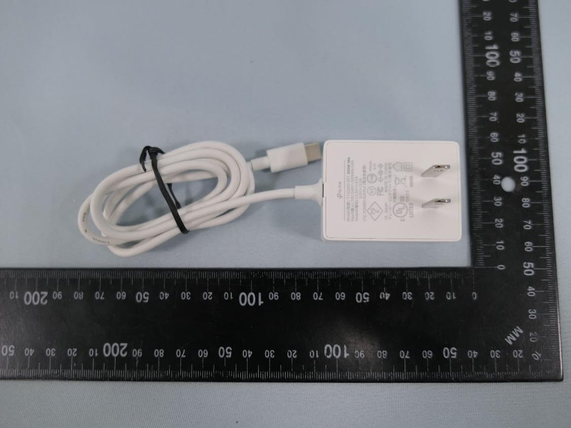
2AXJ4AIRE5
Jan 15, 2024AX3000 Wi-Fi 6 Air Range Extender
Equipment Class
DTS - Digital Transmission System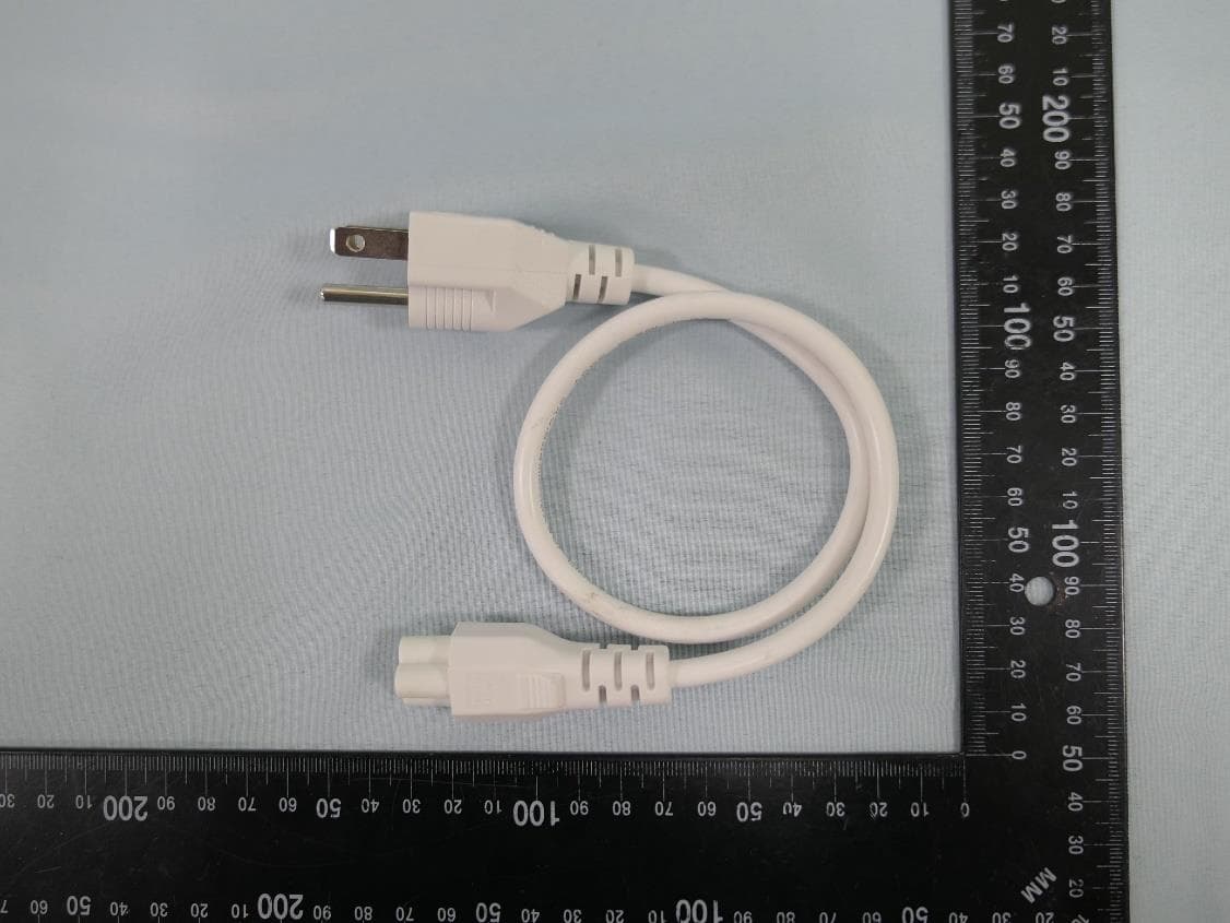
2AXJ4EAP115BRG
Jan 11, 20245GHz 300Mbps Long-range Indoor/Outdoor Access Point
Equipment Class
NII - Unlicensed National Information Infrastructure TX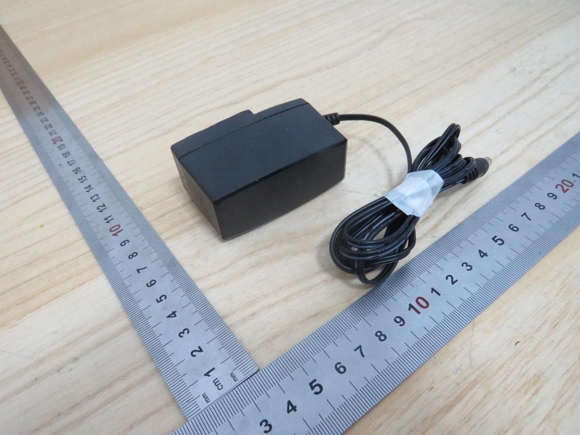
2AXJ4HX510V2
Jan 10, 2024AX3000 Whole Home Mesh Wi-Fi AP
Equipment Class
NII - Unlicensed National Information Infrastructure TX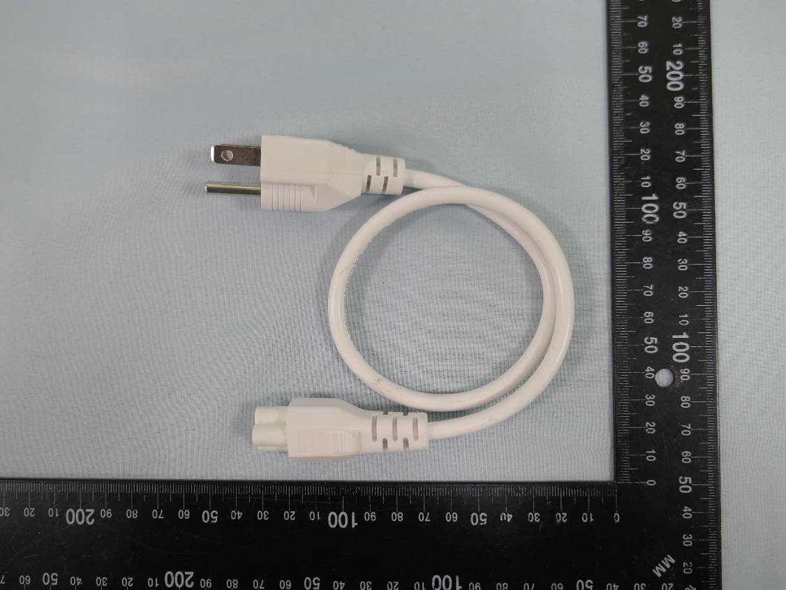
2AXJ4EAP215BRG
Dec 11, 20235GHz 867Mbps Long-range Indoor/Outdoor Access Point
Equipment Class
NII - Unlicensed National Information Infrastructure TX