2AXJ4T2EAC600 Wireless Dual Band PCI Express Adapter
TP-Link Corporation Limited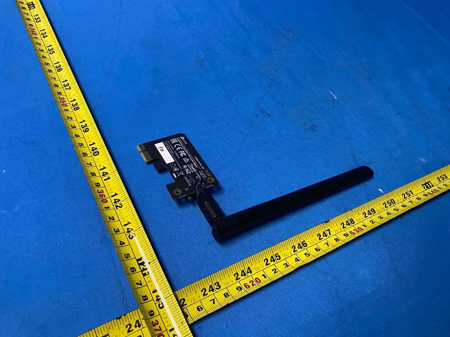
Click to zoom
Application Details
- Equipment Class
- NII - Unlicensed National Information Infrastructure TX
- Date of Grant
- Mar 03, 2021
- Application Purpose
- Original Equipment
- Date of Application
- Mar 02, 2021
- Equipment Note
- AC600 Wireless Dual Band PCI Express Adapter
- Frequency Range
- 5745.00000000 - 5825.00000000
- Company
- TP-Link Corporation Limited
- Country
- Hong Kong
Documents & Files
Document Text
Text extracted from the exhibit documents filed with the FCC. Open a document above to read the original.
Users Manual
© 2021 TP-Link REV1.0.0 1910012971 User Guide AC600 Wireless Dual Band PCI Express Adapter Archer T2E Contents About This Guide 01 Chapter 1 Get to Know About Your Adapter 02 Chapter 2 Connect to a Computer 04 Chapter 3 Use Your Adapter 07 3. 1. Install Driver. . . . . . . . . . . . . . . . . . . . . . . . . . . . . . . . . . . . . . . . . . . . . . . . . . . . . . . . . .08 3. 2. Join a Wireless Network. . . . . . . . . . . . . . . . . . . . . . . . . . . . . . . . . . . . . . . . . . . . . .08 3. 3. Uninstall Driver. . . . . . . . . . . . . . . . . . . . . . . . . . . . . . . . . . . . . . . . . . . . . . . . . . . . . . .09 Chapter 4 Appendix: Troubleshooting 11 01 About This Guide This guide is a complement to Quick Installation Guide. The Quick Installation Guide instructs you on quick installation, and this guide provides the product overview and more detailed instructions for each steps. When using this guide, please notice that features available of the adapter may vary by model and software version. It may also vary by region or ISP. All images, steps, and descriptions in this guide are only examples and may not reflect your actual experience. Conventions In this guide, the following conventions are used: Convention Description Underlined Underlined words or phrases are hyperlinks. You can click to redirect to a website or a specific section. Teal Contents to be emphasized and texts on the web page are in teal, including the menus, items, buttons, etc. Note: Ignoring this type of note might result in a malfunction or damage to the device. Tips: Indicates important information that helps you make better use of your device. *Maximum wireless signal rates are the physical rates derived from IEEE Standard 802.11 specifications. Actual wireless data throughput and wireless coverage are not guaranteed and will vary as a result of 1) environmental factors, including building materials, physical objects, and obstacles, 2) network conditions, including local interference, volume and density of traffic, product location, network complexity, and network overhead, and 3) AP limitations, including rated performance, location, connection quality, and AP condition. More Info • The latest driver can be found at Download Center at https://www.tp-link.com/support. • The Quick Installation Guide (QIG) can be found where you find this guide or inside the package of the product. • Specifications can be found on the product page at https://www.tp-link.com. • A TP-Link Community is provided for you to discuss our products at https://community.tp-link.com. Chapter 1 Get to Know About Your Adapter This chapter introduces the detail of the adapter. 03 Chapter 1 Get to Know about Your Adapter The Archer T2E receives Wi-Fi signals on two separate bands for all your online needs. Choose the 2.4 GHz band for browsing, email and social media, or switch to 5 GHz band for gaming and streaming. The Archer T2E can work with MU-MIMO routers, which provide simultaneous data streams, boosting throughput and efficiency. • Standards: IEEE 802.11b/g/n 2.4GHz, IEEE 802.11a/n/ac 5GHz • Interface: PCI Express • Antenna: 1 Detachable External Antenna • LED: Status • Security: WEP, WPA/WPA2/WPA3, WPA-PSK/WPA2-PSK/WPA3-SAE • Dimensions: 4.76 × 3.09 × 0.85 in (120.8 × 78.5 × 21.5 mm) Chapter 2 Connect to a Computer This chapter introduces how to connect the adapter to your computer. Please note that images are for demonstration only. 05 Chapter 2 Connect to a Computer Follow the steps below to insert the adapter into your computer: 1. Turn off the computer, unplug the power cable and remove the case panel 2. Locate an available PCI-E slot and carefully insert the adapter 06 Chapter 2 Connect to a Computer 3. Connect the antennas to the adapter 4. Replace the case panel, plug in the power cable and turn on your computer Note: If the bracket is not suitable for your computer, detach it from the adapter’s board and replace it with the low-profile bracket provided. Chapter 3 Use Your Adapter This chapter introduces how to install or uninstall your adapter’s Wi-Fi driver, connect to a wireless network on a Windows system. This chapter includes the following sections: • Install Drivers • Join a Wireless Network • Uninstall Drivers 08 Chapter 3 Use Your Adapter 3 1 Install Driver Follow the steps below to set up your adapter: 1 Insert the resource CD into your CD drive and run the Autorun.exe. Note: You can also download the driver from the product’s Support page at www tp-link com. 2 Select Archer T2E and follow the instructions to continue the installation. Note: If you can’t install the driver successfully, disable the antivirus software and firewall, then try again. 3 When the following screen appears, the driver has been installed successfully. 3 2 Join a Wireless Network You can join a wireless network via Windows Wireless Utility. Follow the instructions below to use your computer system’s built-in wireless utility: 1. Click , or (Network icon) on the taskbar. Select the Wi-Fi network you want to join, and click Connect. Enter the network password when prompted. 2. When the network icon changes to or , it indicates a successful network connection. 09 Chapter 3 Use Your Adapter 3 3 Uninstall Driver The software uninstallation steps vary a bit in different systems, please follow the appropriate instructions for your Windows operating system: Windows 8/8.1/10, Windows 7. • Windows 8/8.1/10 Go to Start > Apps, find the TP-Link application. Click Uninstall TP-Link Archer T2E, then follow the on-screen instructions to complete the uninstallation. • Windows 7 Go to Start > All Programs > TP-Link > Uninstall TP-Link Archer T2E. Follow the on-screen instructions to complete the uninstallation. 10 Chapter 3 Use Your Adapter 11 Appendix: Troubleshooting T1 What should I do if the adapter is not detected? • Make sure the adapter is securely located in the appropriate PCI-E slot. • Make sure you meet the system requirements for the adapte…
Text truncated - open the document above for the full version.
Cover Letter(s)
TP-Link Corporation Limited Authority to Act as Agent Date: 2021-02-24 American Certification Body, Inc. 6731 Whittier Avenue Suite C110 McLean, VA 22101 To Whom It May Concern: BTL Inc./Rose Liu is authorized to act on our behalf, until otherwise notified, for applications to American Certification Body, Inc. (ACB). We certify that we are not subject to denial of federal benefits, that includes FCC benefits, pursuant to Section 5301 of the Anti-Drug Abuse Act of 1988, 21 U.S.C. 862. Further, no party, as defined in 47 CFR 1.2002 (b), to the application is subject to denial of federal benefits, that includes FCC benefits. Thank you, Agency Agreement Expiration Date: 2022-02-24 By: __________________________ _______Abby Liang________ (Signature 1 ) (Print name) Title: Regulatory Compliance Manager On behalf of: TP-Link Corporation Limited (Company Name) Telephone: 00852-37585503 1 - Must be signed by applicant contact given for applicant on the FCC site, or by the authorized agent if an appropriate authorized agent letter has been provided. Letters should be placed on appropriate letterhead.
Cover Letter(s)
TP-Link Corporation Limited Request for Confidentiality Date: 2021-02-24 Subject: Confidentiality Request for: 2AXJ4T2E Pursuant to FCC 47 CRF 0.457(d) and 0.459 and IC RSP-100, Section12.4, the applicant requests that a part of the subject FCC application be held confidential. Type of Confidentiality Requested Exhibit Short Term Permanent Block Diagrams Short Term External Photos Short Term Permanent* 1 Internal Photos Short Term Permanent Operation Description/Theory of Operation Short Term Permanent Parts List & Placement/BOM Short Term Permanent Tune-Up Procedure Short Term Permanent Schematics Short Term Test Setup Photos Short Term Permanent* 3 User’s Manual TP-Link Corporation Limited____ has spent substantial effort in developing this product and it is one of the first of its kind in industry. Having the subject information easily available to "competition" would negate the advantage they have achieved by developing this product. Not protecting the details of the design will result in financial hardship. Permanent Confidentiality: The applicant requests the exhibits listed above as permanently confidential be permanently withheld from public review due to materials that contain trade secrets and proprietary information not customarily released to the public. Short-Term Confidentiality: The applicant requests the exhibits selected above as short term confidential be withheld from public view for a period of ___(specify number of days not to exceed 180) 2 ___ days from the date of the Grant of Equipment Authorization and prior to marketing. This is to avoid premature release of sensitive information prior to marketing or release of the product to the public. Applicant is also aware that they are responsible to notify ACB in the event information regarding the product or the product is made available to the public. ACB will then release the documents listed above for public disclosure pursuant to FCC Public Notice DA 04-1705. NOTE for Industry Canada Applications: IC currently only distinguishes Permanent Confidentiality exhibits as shown above. Short Term confidentiality is not considered applicable to IC applications. Sincerely, By: Regulatory Compliance Manager _Abby Liang__________ (Signature/Title 3 ) (Print name) 1 - The asterisked items (*) require further information to be provided to ACB before permanent confidentiality will be extended to these exhibits. Please refer to FCC KDB 726920 and the specific Document link for D01 found at: https://apps.fcc.gov/oetcf/kdb/forms/FTSSearchResultPage.cfm?switch=P&id=41731 and review section II, 3) regarding specific information that must accompany these requests. 2 - Please refer to http://acbcert.com/documents/misc-docs/Memo-Short-Term-Vs-Standard-Confidentiality.pdf for complete details. 3 - Must be signed by applicant contact given for applicant on the FCC site, or by the authorized agent if an appropriate authorized agent letter has been provided. Letters should be placed on appropriate letterhead.
Cover Letter(s)
Non-SDR (Software Defined Radio) Cover Letter Date: 2021.02.24 Refer to KDB 442812 D01 SDR apps Guide v02r03. The following six questions can be used for determining if a radio can elect to be, or must be an SDR. 1. Can the RF parameters of the device be altered through software? □Yes - go to 2. No, not an SDR 2. Can third parties not permitted by the Commission through specific filings modify, configure, or load different software, or make configuration settings to operate the device or host hardware radio frequency parameters (frequency range, modulation type, maximum output power or other radio parameters) in any other way than granted (or expected to be granted)? □Yes, must be an SDR. □No - go to 3. 3. Is the device capable of operating in any other way than granted, or will be, granted? □Yes, - go to 4. □No - go to 5. 4. Is this a Part 15 client Device as defined in Section 15.202 (as opposed to a master device)? □Yes, qualifies as a part 15 client devices - go to 5. □No, must be an SDR. 5. Does the manufacturer elect SDR? □Yes, elects to be an SDR. □No, Not an SDR Final conclusion: According to the above questions reply, we can confirm this AC600 Wireless Dual Band PCI Express Adapter (FCC ID: 2AXJ4T2E) must be a Non-SDR. Name: Abby Liang Position: Regulatory Compliance Manager TP-Link Corporation Limited
External Photos
Report No.: 2012C099 Page 1 of 5 ATTACHMENT PHOTOGRAPHS OF EUT Report No.: 2012C099 Page 2 of 5 Antenna
ID Label/Location Info
C B A 12 C 345678 B E D D A 9 料号: 12345 E 6789 Archer T2E(US)1.0 PCB产品规格丝印 A1 Archer T2E(US)1.0 陈萍萍 202010 尺寸图 菲林图 4.754mm Model: Archer T2E AC600 Wireless Dual Band PCI Express Adapter TP-Link Corporation Limited Suite 901, New East Ocean Centre, Tsim Sha Tsui, Hong Kong S/N:XXXXXXXXXXXXX US/ 1.0 FCC ID: 2AXJ4T2E IC: 26583-T2E 2.332mm *SN由工厂打印至空白标贴7210500003后粘贴于PCB指定位置 丝印尺寸:42.655*25.887mm
Internal Photos
Report No.: 2012C099 Page 3 of 5 Report No.: 2012C099 Page 4 of 5 Report No.: 2012C099 Page 5 of 5
RF Exposure Info
Report No.: BTL-FCCP-4-2012C099 Page 1 of 4 FCC RF EXPOSURE REPORT FCC ID: 2AXJ4T2E Project No. : 2012C099 Equipment : AC600 Wireless Dual Band PCI Express Adapter Brand Name : tp-link Test Model : Archer T2E Series Model : N/A Applicant : TP-Link Corporation Limited Address : Room 901, 9/F. , New East Ocean Centre, 9 Science Museum Road, Tsim Sha Tsui, Kowloon, Hong Kong Manufacturer : TP-Link Corporation Limited Address : Room 901, 9/F. , New East Ocean Centre, 9 Science Museum Road, Tsim Sha Tsui, Kowloon, Hong Kong Date of Receipt : Dec. 26, 2020 Date of Test : Dec. 28, 2020 ~ Feb. 08, 2021 Issued Date : Feb. 25, 2021 Report Version : R00 Test Sample : Engineering Sample No.: DG2028121658 Standard(s) : FCC Guidelines for Human Exposure IEEE C95.1 & FCC Part 2.1091 FCC Title 47 Part 2.1091, OET Bulletin 65 Supplement C The above equipment has been tested and found compliance with the requirement of the relative standards by BTL Inc. Prepared by : Sheldon Ou Approved by : Ethan Ma Add: No.3, Jinshagang 1st Road, Shixia, Dalang Town,Dongguan, Guangdong, China. Te l : +86-769-8318-3000 Web: www.newbtl.com Report No.: BTL-FCCP-4-2012C099 Page 2 of 4 REPORT ISSUED HISTORY Report Version Description Issued Date R00 Original Issue Feb. 25, 2021 Report No.: BTL-FCCP-4-2012C099 Page 3 of 4 1. TEST FACILITY The test facilities used to collect the test data in this report is at the location of No.3,Jinshagang 1st Road, Shixia, Dalang Town, Dongguan, Guangdong, China. BTL's Test Firm Registration Number for FCC: 357015 BTL's Designation Number for FCC: CN1240 2. MPE CALCULATION METHOD Calculation Method of RF Safety Distance: where: S = power density P = power input to the antenna G = power gain of the antenna in the direction of interest relative to an isotropic radiator R = distance to the center of radiation of the antenna Table for Filed Antenna: For 2.4GHz: Ant. Brand P/N Antenna Type Connector Gain (dBi) 1 tp -link 3101503058 Dipole N/A 2.35 Note: The antenna gain and beamforming gain is provided by the manufacturer. For 5GHz: Ant. Brand P/N Antenna Type Connector Gain (dBi) Note 1 tp -link 3101503058 Dipole RP-SMA-F 4.52 Band 1 1 tp -link 3101503058 Dipole RP-SMA-F 4.72 Band 2 1 tp -link 3101503058 Dipole RP-SMA-F 4.83 Band 3 1 tp -link 3101503058 Dipole RP-SMA-F 3.96 Band 4 Note: The antenna gain and beamforming gain is provided by the manufacturer. Report No.: BTL-FCCP-4-2012C099 Page 4 of 4 3. TEST RESULTS For 2.4GHz: Antenna Gain (dBi) Antenna Gain (numeric) Max. Output Power (dBm) Max. Output Power (mW) Power Density (S) (mW/cm 2 ) Limit of Power Density (S) (mW/cm 2 ) Test Result 2.35 1.7179 18.39 69.0240 0.02360 1 Complies For 5GHz UNII-1: Antenna Gain (dBi) Antenna Gain (numeric) Max. Output Power (dBm) Max. Output Power (mW) Power Density (S) (mW/cm 2 ) Limit of Power Density (S) (mW/cm 2 ) Test Result 4.52 2.8314 19.79 95.2796 0.05370 1 Complies For 5GHz UNII-2A: Antenna Gain (dBi) Antenna Gain (numeric) Max. Output Power (dBm) Max. Output Power (mW) Power Density (S) (mW/cm 2 ) Limit of Power Density (S) (mW/cm 2 ) Test Result 4.72 2.9648 18.82 76.2079 0.04497 1 Complies For 5GHz UNII-2C: Antenna Gain (dBi) Antenna Gain (numeric) Max. Output Power (dBm) Max. Output Power (mW) Power Density (S) (mW/cm 2 ) Limit of Power Density (S) (mW/cm 2 ) Test Result 4.83 3.0409 18.60 72.4436 0.04385 1 Complies For 5GHz UNII-3: Antenna Gain (dBi) Antenna Gain (numeric) Max. Output Power (dBm) Max. Output Power (mW) Power Density (S) (mW/cm 2 ) Limit of Power Density (S) (mW/cm 2 ) Test Result 3.96 2.4889 18.39 69.0240 0.03419 1 Complies End of Test Report
Schematics
55 44 33 22 11 D D C C B B A A WAKE PERSTPERP0 PETP0 PERN0 PETN0 REFCLK-REFCLK+ WAKEN PRSNT PRSNT VDD33_PCIE VDD33_PCIE PRSNT {3}PERST {4} PRSNT {3} PETN0 {4} PETP0 {4} WAKEN {4} REFCLK+ {4}REFCLK- {4}PERP0 {4}PERN0 {4} TP-Link Corporation Limited TitleSize Document Number Rev EngineersDate: Sheet of B 1.0 Archer T2E(US) Friday, November 20, 2020 3 4 03_Power_PCIe Lijiakang TP-Link Corporation Limited TitleSize Document Number Rev EngineersDate: Sheet of B 1.0 Archer T2E(US) Friday, November 20, 2020 3 4 03_Power_PCIe Lijiakang TP-Link Corporation Limited TitleSize Document Number Rev EngineersDate: Sheet of B 1.0 Archer T2E(US) Friday, November 20, 2020 3 4 03_Power_PCIe Lijiakang M2Screw Hole 1 1 3 3 4 4 5 5 6 6 7 7 8 8 2 2 M1Screw Hole 1 1 3 3 4 4 5 5 6 6 7 7 8 8 2 2 C18721.5pF_25V_NC R30 0R C1871 1.5pF_25V_NC C18741.5pF_25V R205 0R R204 0R C1873 1.5pF_25V U4 PCIE +12V_1 B1 +12V_2 B2 +12V_3 B3 GND_1 B4 SMDAT B6 SMCLK B5 GND_2 B7 3.3V_1 B8 TRST# B9 33VAUX B10 WAKE# B11 RSVD B12 GND_3 B13 PETp0 B14 PETn0 B15 GND_4 B16 PRSNT2# B17 GND_5 B18 PRSNT1# A1 +12V_4 A2 +12V_5 A3 GND_6 A4 TCK A5 TDI A6 YFO A7 TMS A8 3.3V_2 A9 3.3V_3 A10 PERST_L A11 GND_7 A12 REFCLK+ A13 REFCLK- A14 GND_8 A15 PERp0 A16 PERn0 A17 GND_9 A18 55 44 33 22 11 D D C C B B A A RF5TRXBTG_RFINBTG_RFIP VD10 V33_SYNVDD_IO_1 VD10 VDD33 VDD33VD33X VD10 VDD33 VDD33 VDD33BT_V33_SYN VDD33 VD10VD10D_WL VD10 VDD33 VD10AVD10VD10VD10 VDD_IOVDD33 LED_WL HSDM PERP0 HSDP PERN0 LED_BT HSIPHSINPERSTPERSTWAKEn VDD33 HSOPHSON COEX3 VDD33 TEST_MD_SELSPS_LDO_SEL VDD_IO_1BT_V33_SYN VDD33_PCIe VDD33 V33_SYNVD33X VD10 VD10_SYNVD10AVD10D_WL BTG_RFINBTG_RFIP TRN_1TRP_1 VDD33 LED_WL VD10_SYN VDD_IO RF5TRX VDD33 VDD33 VDD33 VDD33_PCIE PETP0 {3} PETN0 {3} PERP0 {3}PERN0 {3} WAKEN {4} REFCLK- {3}REFCLK+ {3} PERST {3} TP-Link Corporation Limited TitleSize Document Number Rev EngineersDate: Sheet of B 1.0 Archer T2E(US) Friday, November 20, 2020 4 4 04_RTL8821CE Lijiakang TP-Link Corporation Limited TitleSize Document Number Rev EngineersDate: Sheet of B 1.0 Archer T2E(US) Friday, November 20, 2020 4 4 04_RTL8821CE Lijiakang TP-Link Corporation Limited TitleSize Document Number Rev EngineersDate: Sheet of B 1.0 Archer T2E(US) Friday, November 20, 2020 4 4 04_RTL8821CE Lijiakang U6 DP1608-A2455BK GND_1 2 COMMON 5 HB 1 LB 3 GND_3 6 GND_2 4 C12 0.1uF_6.3V C41 0.1uF_6.3V C16 0.1uF_6.3V L10452.7nH_NC C26 0.1uF_6.3V C5 1.0pF_25V C9822pF_50V SH1 SH GND_1 1 R10060R C4 3.3pF_25V C4310pF_50V R22 100K C58 0.1uF_6.3V C18792.4nH R17 100K TP_HSDP C1886 0.1uF_6.3V C18821.5pF_25V C39 0.1uF_6.3V (29 balls) U5C RTL8821CE HSIP C10 HSIN D10 HSOP E10 HSON F10 REFCLK_P G10 REFCLK_N H10 PERSTn H8 CLKREQn H7 WAKEn J8 WL_LED C3 BT_LED[1] C4 GPIO[11] C7 GPIO[9] J7 GPIO[6] H5 GPIO[7] J5 GPIO[12] J6 EECS C2 GND_V33USB B9 HSDM A10 HSDP B10 RREF F9 GPIO[0] B6 GPIO[1] B5 GPIO[3] C5 GPIO[2] C6 NFC_RF_DIS E8 NFC_INT E7 NFC_CLK F8 NFC_DATA G8 (21 balls) U5E RTL8821CE GND_SPS J10 GND_1 B3 GND_19 J3 GND_2 C1 GND_3 C8 GND_4 D2 GND_5 D3 GND_6 D7 GND_7 D8 GND_8 E2 GND_9 E3 GND_10 F2 GND_11 F3 GND_12 G3 GND_13 G6 GND_14 G7 GND_15 H2 GND_16 H3 GND_17 H4 GND_18 H6 GND_20 J4 GND_21 E9 C10 0.1uF_6.3V (8 balls) U5D RTL8821CE GPIO[4] A6 GPIO[5] A5 BT_LOG D6 EESK F7 GPIO[13] F6 GPIO[14] E6 GPIO[15] E5 CHIP_EN H9 C18780.5pF_50V C61 10uF_6.3V R10 27R_1% C1883 1.5pF_25V C1866NC L610nH C25 0.1uF_6.3V C24 0.1uF_6.3V C60 22uF_6.3V C303.3pF_25V C6 1.2pF_25V C35 0.1uF_6.3V C99 15pF_50V C3 1.0pF_25V R23 100K C900.2pF_50V C59 10uF_6.3V C1888 0.1uF_6.3V TP_HSDM R16 10K_0402 C57 0.1uF_6.3V C31 0.1uF_6.3V C37 0.1uF_6.3V C190.1uF_6.3V R21 100K R12 6.2K_1%_0402 C21 0.1uF_6.3V R1008 0.6nH C20 0.1uF_6.3V (15 BALLS) U5A RTL8821CE WLS1_2G/BTS0_N A1 WLS1_2G/BTS0_P B1 WLS0_5G_RFIP E1 WLS0_5G_RFIO F1 WLS0_2G_RFIP J1 WLS0_2G_RFIO H1 PAPE_G D5 LNAON_G D4 DPDT_SEL_P E4 DPDT_SEL_N F5 PAPE_A G5 LNAON_A G4 WL_TSSI F4 XI K3 XO K4 JH11 1 2 3 4 5 C38 0.1uF_6.3V L10442.7nH_NC C8 3.3pF_25V R15 100K C18811.5pF_25V_NC R11 0R C34NC C1887 0.1uF_6.3V C18770.5pF_50V C32 0.1uF_6.3V C29 1uF_6.3V C890.4pF_50V C1 2.2pF_25V D2 LED_BASE_1H_1L 12 R34 0R_NC C17 0.1uF_6.3V C332.4nH L710nH C11 0.1uF_6.3V (26 balls) U5B RTL8821CE WL_VD105_RXA D1 BT_VD105_RTX B2 WL_VD105_TRX K1 BT_V105_LOBUF A4 VD10D_BT B8 WL_VD105_SYN J2 VD10A K6 VD10D_WL J9 V10_VDDTX G9 WLA_VDD33_PA G1 WL_VD33_SYN K2 WLG_VDD33_PA G2 BT_VD33_SYN A3 VD33_IO_1 B4 VD33X K5 VDD_IO K7 V10_USB D9 VDD_IO_1 A7 VD33_IO K8 LX_SPS K10 VDS33SPS K9 VBAT_IN A8 VBAT_OUT A9 VBAT_EN B7 V33_USB C9 BT_VD33_PAD A2 C15 10uF_6.3V L12.7nH R1007 0R C28 0.1uF_6.3V C42 10uF_6.3V R18 100K L5 2.2uH_1.8A Y140MHz_9PPM_14pF XOUT 3 XIN 1 GND_1 2 GND_2 4 R38 0R C1889 0.1uF_6.3V C1880 1.5pF_25V_NC C1884 0.1uF_6.3V L22.7nH C44 10uF_6.3V R678 510R C180.1uF_6.3V C27 0.1uF_6.3V
Test Report
Report No.: BTL-FCCP-3-2012C099 Page 1 of 21 FCC DFS Test Report FCC ID: 2AXJ4T2E This report concerns: Original Grant Project No. : 2012C099 Equipment : AC600 Wireless Dual Band PCI Express Adapter Brand Name : tp-link Test Model : Archer T2E Series Model : N/A Applicant : TP-Link Corporation Limited Address : Room 901, 9/F. , New East Ocean Centre, 9 Science Museum Road, Tsim Sha Tsui, Kowloon, Hong Kong Manufacturer : TP-Link Corporation Limited Address : Room 901, 9/F. , New East Ocean Centre, 9 Science Museum Road, Tsim Sha Tsui, Kowloon, Hong Kong Date of Receipt : Dec. 26, 2020 Date of Test : Dec. 28, 2020 ~ Feb. 08, 2021 Issued Date : Feb. 25, 2021 Report Version : R00 Test Sample : Engineering Sample No.: DG2028121658 Standard(s) : FCC CFR Title 47, Part 15, Subpart E FCC KDB 789033 D02 General U-NII Test Procedures New Rules v02r01 FCC KDB 905462 D02 UNII DFS Compliance Procedures New Rules v02 FCC KDB 905462 D03 UNII Clients Without Radar Detection New Rules v01r02 The above equipment has been tested and found compliance with the requirement of the relative standards by BTL Inc. Prepared by : Sheldon Ou Approved by : Ethan Ma Add: No.3, Jinshagang 1st Road, Shixia, Dalang Town,Dongguan, Guangdong, China. Te l : +86-769-8318-3000 Web: www.newbtl.com Report No.: BTL-FCCP-3-2012C099 Page 2 of 21 Declaration BTL represents to the client that testing is done in accordance with standard procedures as applicable and that test instruments used has been calibrated with standards traceable to international standard(s) and/or national standard(s). BTL's reports apply only to the specific samples tested under conditions. It is manufacture’s responsibility to ensure that additional production units of this model are manufactured with the identical electrical and mechanical components. BTL shall have no liability for any declarations, inferences or generalizations drawn by the client or others from BTL issued reports. The report must not be used by the client to claim product certification, approval, or endorsement by NVLAP, NIST, A2LA, or any agency of the U.S. Government. This report is the confidential property of the client. As a mutual protection to the clients, the public and ourselves, the test report shall not be reproduced, except in full, without our written approval. BTL’s laboratory quality assurance procedures are in compliance with the ISO/IEC 17025 requirements, and accredited by the conformity assessment authorities listed in this test report. BTL is not responsible for the sampling stage, so the results only apply to the sample as received. The information, data and test plan are provided by manufacturer which may affect the validity of results, so it is manufacturer’s responsibility to ensure that the apparatus meets the essential requirements of applied standards and in all the possible configurations as representative of its intended use. Limitation For the use of the authority's logo is limited unless the Test Standard(s)/Scope(s)/Item(s) mentioned in this test report is (are) included in the conformity assessment authorities acceptance respective. Please note that the measurement un certainty is provided for informational purpose only and are not use in determining the Pass/Fail results. Report No.: BTL-FCCP-3-2012C099 Page 3 of 21 Table of Contents Page REPORT ISSUED HISTORY 4 1 . TEST FACILITY 5 2 . TEST ENVIRONMENT CONDITIONS 5 3 . SUMMARY OF TEST RESULTS 5 4 . GENERAL INFORMATION 6 4.1 GENERAL DESCRIPTION OF EUT 6 4.2 MAXIMUM OUTPUT POWER AND E.I.R.P. 8 4.3 DESCRIPTION OF TEST MODES 8 5 . U-NII DFS RULE REQUIREMENTS 9 5.1 WORKING MODES AND REQUIRED TEST ITEMS 9 5.2 TEST LIMITS AND RADAR SIGNAL PARAMETERS 10 6 . MEASUREMENT INSTRUMENTS LIST 11 7 . DYNAMIC FREQUENCY SELECTION (DFS) 12 7.1 DFS MEASUREMENT SYSTEM 12 7.2 CALIBRATION OF DFS DETECTION THRESHOLD LEVEL 15 7.3 DEVIATION FROM TEST STANDARD 15 8 . TEST RESULTS 16 8.1 SUMMARY OF DFS TEST RESULT 16 8.2 DFS DETECTION THRESHOLD 17 8.3 CHANNEL MOVE TIME AND CHANNEL CLOSING TRANSMISSION TIME 18 8.4 NON-OCCUPANCY PERIOD 20 9 . EUT TEST PHOTO 21 Report No.: BTL-FCCP-3-2012C099 Page 4 of 21 REPORT ISSUED HISTORY Report Version Description Issued Date R00 Original Issue. Feb. 25, 2021 Report No.: BTL-FCCP-3-2012C099 Page 5 of 21 1. TEST FACILITY The test facilities μsed to collect the test data in this report is TR16 at the location of No.3, Jinshagang 1st Road, Shixia, Dalang Town, Dongguan, Guangdong, China. 2. TEST ENVIRONMENT CONDITIONS Test Item Temperature Humidity Test Voltage Tested By Dynamic Frequency Selection (DFS) 24°C 49% DC 3.3V Grani Zhou 3. SUMMARY OF TEST RESULTS Test procedures according to the technical standard(s): FCC CFR Title 47, Part 15, Subpart E Standard(s) Section Test Item Test Result Judgment Remark 15.407(h) Transmit Power Control (TPC) and Dynamic Frequency Selection (DFS) ------ PASS ------ Report No.: BTL-FCCP-3-2012C099 Page 6 of 21 4. GENERAL INFORMATION 4.1 GENERAL DESCRIPTION OF EUT Equipment AC600 Wireless Dual Band PCI Express Adapter Brand Name tp-link Test Model Archer T2E Series Model N/A Model Difference(s) N/A Software Version 2020,2024.0.10.127 Hardware Version 1.0 Power Source DC voltage supplied from external power supply Power Rating DC 3.3V Operation Frequency Band(s) UNII-2A: 5250 MHz ~ 5350 MHz UNII-2C: 5470 MHz ~ 5725 MHz Modulation Type IEEE 802.11a/n/ac: OFDM Bit Rate of Transmitter IEEE 802.11a: 54/48/36/24/18/12/9/6 Mbps IEEE 802.11n: up to 150 Mbps IEEE 802.11ac: up to 433.3 Mbps Operating Mode(s) Master Client device without radar detection Client device with radar detection Max. Output Power_UNII-2A IEEE 802.11ac (VHT20):18.82 dBm (0.0762 W) Max. Output Power_UNII-2C IEEE 802.11a: 18.60 dBm (0.0724 W) Report No.: BTL-FCCP-3-2012C099 Page 7 of 21 Note: 1. For a more detailed features description, please refer to the manufacturer’s specifications or the user's manual. 2. Channel List: IEEE 802.11a IEEE 802.11n(HT20) IEEE 802.11ac(VHT20) IEEE 802.11n(HT40) IEEE 80…
Text truncated - open the document above for the full version.
Test Report
Report No.: BTL-FCCP-2-2012C099 Page 1 of 237 FCC Radio Test Report FCC ID: 2AXJ4T2E Thi s report concerns: Original Grant Project No. : 2012C099 Equipment : AC600 Wireless Dual Band PCI Express Adapter Brand Name : tp-link Test Model : Archer T2E Series Model : N/A Applicant : TP-Link Corporation Limited Address : Room 901, 9/F. , New East Ocean Centre, 9 Science Museum Road, Tsim Sha Tsui, Kowloon, Hong Kong Manufacturer : TP-Link Corporation Limited Address : Room 901, 9/F. , New East Ocean Centre, 9 Science Museum Road, Tsim Sha Tsui, Kowloon, Hong Kong Date of Receipt : Dec. 26, 2020 Date of Test : Dec. 28, 2020 ~ Feb. 08, 2021 Issued Date : Mar. 03, 2021 Report Version : R01 Test Sample : Engineering Sample No.:DG2028121656 for radiated, DG2028121658 for conducted. Standard(s) : FCC CFR Title 47, Part 15, Subpart E ANSI C63.10-2013 FCC KDB 789033 D02 General UNII Test Procedures New Rules v02r01 FCC KDB 662911 D01 Multiple Transmitter Output v02r01 T he above equipment has been tested and found compliance with the requirement of the relative standards by BTL Inc. Prepared by : Sheldon Ou Approved by : Ethan Ma Add: No.3, Jinshagang 1st Road, Shixia, Dalang Town,Dongguan, Guangdong, China. Te l : +86-769-8318-3000 Web: www.newbtl.com Report No.: BTL-FCCP-2-2012C099 Page 2 of 237 Declaration BTL represents to the client that testing is done in accordance with standard procedures as applicable and that test instruments used has been calibrated with standards traceable to international standard(s) and/or national standard(s). BTL's reports apply only to the specific samples tested under conditions. It is manufacture’s responsibility to ensure that additional production units of this model are manufactured with the identical electrical and mechanical components. BTL shall have no liability for any declarations, inferences or generalizations drawn by the client or others from BTL issued reports. The report must not be used by the client to claim product certification, approval, or endorsement by NVLAP, NIST, A2LA, or any agency of the U.S. Government. This report is the confidential property of the client. As a mutual protection to the clients, the public and ourselves, the test report shall not be reproduced, except in full, without our written approval. BTL’s laboratory quality assurance procedures are in compliance with the ISO/IEC 17025 requirements, and accredited by the conformity assessment authorities listed in this test report. BTL is not responsible for the sampling stage, so the results only apply to the sample as received. The information, data and test plan are provided by manufacturer which may affect the validity of results, so it is manufacturer’s responsibility to ensure that the apparatus meets the essential requirements of applied standards and in all the possible configurations as representative of its intended use. Limitation For the use of the authority's logo is limited unless the Test Standard(s)/Scope(s)/Item(s) mentioned in this test report is (are) included in the conformity assessment authorities acceptance respective. Please note that the measurement uncertainty is provided for informational purpose only and are not use in determining the Pass/Fail results. Report No.: BTL-FCCP-2-2012C099 Page 3 of 237 Table of Contents Page REPORT ISSUED HISTORY 6 1 . SUMMARY OF TEST RESULTS 7 1.1 TEST FACILITY 8 1.2 MEASUREMENT UNCERTAINTY 8 1.3 TEST ENVIRONMENT CONDITIONS 9 2 . GENERAL INFORMATION 10 2.1 GENERAL DESCRIPTION OF EUT 10 2.2 TEST MODES 13 2.3 PARAMETERS OF TEST SOFTWARE 15 2.4 DUTY CYCLE 16 2.5 BLOCK DIAGRAM SHOWIN…
Text truncated - open the document above for the full version.
Contact Information
Applicant
Sarah Wang
Technical Contact
BTL Inc.Steven Lu
[email protected]86-769-83183000
No.3 Jinshagang 1st Rd, Shixia, Dalang · Dongguan City · China
Non-Technical Contact
BTL Inc.Rose Liu
[email protected]86-769-83183000
Test Firm
BTL Inc.Sophia Huang
[email protected]+86-769-83183000
Technical Specifications
| # | Rule Parts | Frequency Range | Power Output |
|---|---|---|---|
| 4 | 15E | 5.75 GHz - 5.83 GHz | 69.00 mW |
Other Applications from TP-Link Corporation Limited
2AXJ4TXE50UH
Jan 28, 2024AXE3000 Wi-Fi 6E High Gain Wireless USB Adapter
Equipment Class
NII - Unlicensed National Information Infrastructure TX
2AXJ4AIRE5
Jan 15, 2024AX3000 Wi-Fi 6 Air Range Extender
Equipment Class
DTS - Digital Transmission System
2AXJ4EAP115BRG
Jan 11, 20245GHz 300Mbps Long-range Indoor/Outdoor Access Point
Equipment Class
NII - Unlicensed National Information Infrastructure TX
2AXJ4HX510V2
Jan 10, 2024AX3000 Whole Home Mesh Wi-Fi AP
Equipment Class
NII - Unlicensed National Information Infrastructure TX
2AXJ4EAP215BRG
Dec 11, 20235GHz 867Mbps Long-range Indoor/Outdoor Access Point
Equipment Class
NII - Unlicensed National Information Infrastructure TX