2AXR6-EL192WIRELESS CHARGING LAMP
STARLINE USA INC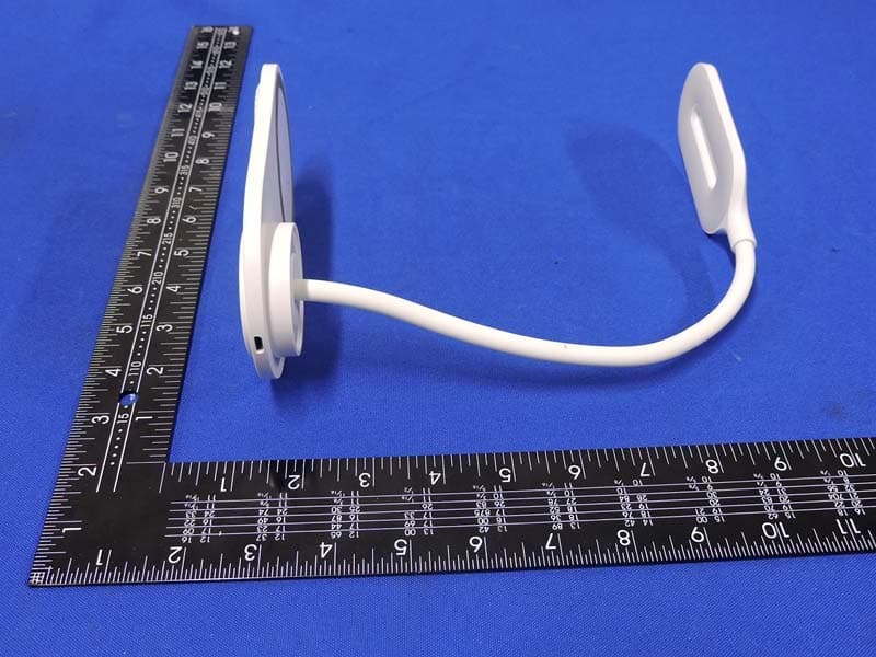
Click to zoom
Application Details
- Equipment Class
- DCD - Part 15 Low Power Transmitter Below 1705 kHz
- Date of Grant
- Oct 29, 2020
- Application Purpose
- Original Equipment
- Date of Application
- Oct 29, 2020
- Equipment Note
- WIRELESS CHARGING LAMP
- Frequency Range
- 0.11150000 - 0.12500000
- Company
- STARLINE USA INC
- Country
- United States
Documents & Files
Document Text
Text extracted from the exhibit documents filed with the FCC. Open a document above to read the original.
Users Manual
EL192 10W Wireless Charging LED lamp User Manual Product OutlineINSTRUCTIONS Specifications Model: EL192 Input: 5V/2A 9V/2A Input Power: 18W(max) Charging efficiency: 70%-80% Output Power: 5V/1A 9V/1.1A Standard Accessories 1 x Wireless Charging LED Lamp 1 x USB Charging Cable 1 x User Manual Attention 1. Keep charger dry, do not spill wter on vharger. 2. Power off when cleaning charger. 3. Use on normal temperature 15°C ~ 45°C degree. Flexible lamp-post USB Charging post Lamp switch LED lamp Wireless charging panelnon-slip mat 1. Connect wireless charger (or with QC 2.0/3.0 Adapter-not included).GREEN indicator will light up in 3 seconds then turn in BLUE in 15 seconds as Standby Mode. 2. Put your phone on the wireless charging area then phone starts to charge and the inidcator flashing in BLUE and indicator will stop flashing once your device is fully charged. 3. Turn the LED lamp on/off by touching the on/off logo switch. There're 3 modes, Warm-Cold-Subdued-OFF. EL192 Lampe de chargement sans fil à DEL 10W GUIDE DE L’UTILISATEUR DESCRIPTION DU PRODUITINSTRUCTIONS Spécifications Modèle: EL192 Entrée: 5V/2A 9V/2A Puissance d’entrée: 18W(max) Efficacité de chargement : 70%-80% Uissance de sortie: 5V/1A 9V/1.1A Accessoires De Base 1 x Wireless Charging LED Lamp 1 x USB Charging Cable 1 x User Manual Attention 1. Gardez le chargeur au sec et ne l’éclaboussez pas d’eau 2. Mettez l’appareil en arrêt lorsque vous le nettoyez 3. Utilisez en présence de températures normales entre 15 et 45 degrés environ Bras de lampe flexible Port de chargement USB Interrupteur de la lampe Lampe à DEL Panneau de chargement sans fil Tapis antidérapant 1. Connectez le chargeur sans fil (ou au moyen de l’adaptateur QC 2.0-3.0 non inclus). L’indicateur VERT s’allumera après 3 secondes puis deviendra bleu après 15 secondes en mode « attente ». 2. Déposez votre téléphone sur l’aire de chargement puis le téléphone commencera à se recharger. L’indicateur bleu clignotera et arrêtera de clignoter lorsque le chargement sera complété. 3. Allumez la lampe à DEL au moyen du bouton « marche/arrêt » situé sur le logo. Il y a 3 modes soit Chaud, Froid, Discret ou éteint. Adaptateur mural non inclus FRONT BACK Wall Adapter not included The distance between user and products should be no less than 20cm FCC Warning Statement Changes or modifications not expressly approved by the party responsible for compliance could void the user’s authority to operate the equipment. This equipment has been tested and found to comply with the limits for a Class B digital device, pursuant to Part 15 of the FCC Rules. These limits are designed to provide reasonable protection against harmful interference in a residential installation. This equipment generates uses and can radiate radio frequency energy and, if not installed and used in accordance with the instructions, may cause harmful interference to radio communications. However, there is no guarantee that interference will not occur in a particular installation. If this equipment does cause harmful interference to radio or television reception, which can be determined by turning the equipment off and on, the user is encouraged to try to correct the interference by one or more of the following measures: - Reorient or relocate the receiving antenna. - Increase the separation between the equipment and receiver. - Connect the equipment into an outlet on a circuit different from that to which the receiver is connected. - Consult the dealer or an experienced radio/TV technician for help. This device complies with part 15 of the FCC rules. Operation is subject to the following two conditions (1) this device may not cause harmful interference, and (2) this device must accept any interference received, including interference that may cause undesired operation. La distance entre l'utilisateur et les produits ne doit pas être inférieure à 20 cm. Avertissement de la FCC Les changements ou modifications non expressément approuvés par la partie responsable de la conformité pourraient annuler la capacité de l'utilisateur de faire fonctionner l'équipement. Cet équipement a été testé et jugé conforme aux limites applicables aux appareils numériques de classe B, conformément à la partie 15 des règles de la FCC. Ces limites sont conçues pour fournir une protection raisonnable contre les interférences nuisibles dans une installation résidentielle. Cet équipement génère, utilise et peut transmettre des radiofréquences et, s'il n'est pas installé et utilisé conformément aux instructions, peut causer des interférences nuisibles aux communications radio. Toutefois, il n'est pas garanti qu'il n'y aura pas d'interférence dans une installation particulière. Si cet équipement provoque de l'interférence à la réception radio ou télévision, qui peut être déterminée en éteignant et en allumant l'équipement, l'utilisateur est encouragé à essayer de corriger l'interférence par un ou plusieurs des moyens suivants: - Réorienter ou relocaliser l'antenne de réception. - Augmenter la distance entre l'équipement et le récepteur. - Brancher l'équipement sur une prise d'un circuit différent de celui auquel le récepteur est connecté. - Consulter le revendeur ou un technicien radio/TV expérimenté pour obtenir de l'aide. Cet appareil est conforme à la partie 15 des règles de la FCC. Son fonctionnement est soumis aux deux conditions suivantes : (1) cet appareil ne doit pas causer d'interférences nuisibles, et (2) cet appareil doit accepter toutes les interférences reçues, y compris celles qui peuvent provoquer un dysfonctionnement.
Cover Letter(s)
October 26, 2020 Equipment Autorisation Division Federal Communications Commission 7435 Oakland Mills Road Columbia, MD 21046 FCC ID: 2AXR6-EL192 Product Name: WIRELESS CHARGING LAMP Request for Confidentiality Pursuant to Sections 0.457 and 0.459 of the commissions rules, we hereby request that the following documents be held confidential: • Schematics • Block diagram • Operation description These materials contain trade secrets and proprietary information and are not customarily released to the public. The public disclosure of this information might be harmful to the company and provide unjustified benefits to our competitors. <Signature>: Name:Mason Lapsker Title: Applicant Company:STARLINE USA INC.
Cover Letter(s)
October 26, 2020 Federal Communications Commission Authorization & Evaluation Division 7345 Oakland Mills Road Columbia, Maryland 21046 Authority to Act as Agent On our behalf, I appoint Shenzhen Timeway Testing Laboratories/ Zone C, 1st Floor, Zone C, 1st Floor, Block B, Jun Xiang Da Building, Zhongshan Park Road West, Tong Le Village, Nanshan District, Shenzhen, China (Name of Agent company name and address) to act as our agent in the preparation of this application for equipment certification. I certify that submitted documents properly describe the device or system for which equipment certification is sought. I also certify that each unit manufactured, imported or marketed, as defined in the Federal Communications Commission’s regulations will have affixed to it a label identical to that submitted for approval with this application. For instances where our authorized agent signs the application for certification on our behalf, I acknowledge that all responsibility for complying with the terms and conditions for certification, still resides with STARLINE USA INC./ 3036 ALT BLVD.,GRAND ISLAND, NEW YORK 14072 USA <Signature>: Name:Mason Lapsker Title: Applicant Company:STARLINE USA INC.
ID Label/Location Info
Label Location
ID Label/Location Info
WIRELESS CHARGING LAMP This device complies with part 15 of the FCC rules. Operation is subject to the following two conditions (1) this device may not cause harmful interference, and (2) this device must accept any interference received, including interference that may cause undesired operation. FCC ID2AXR6-EL192
RF Exposure Info
FCC ID: 2AXR6-EL192 RF Exposure Evaluation 1 Measuring Standard KDB 680106 D01 RF Exposure Wireless Charging Apps v03 2 Requirements According to the item 5 of KDB 680106 D01 RF Exposure Wireless Charging App v03: (1) Power transfer frequency is less than 1 MHz. Yes,0.1115-0.205MHz (2) Output power from each primary coil is less than or equal to 15 watts. Yes, Max power 10W (3) The transfer system includes only single primary and secondary coils. This includes charging systems that may have multiple primary coils and clients that are able to detect and allow coupling only between individual pairs of coils. Yes. (3) Client device is placed directly in contact with the transmitter. Yes (5) Mobile exposure conditions only (portable exposure conditions are not covered by this exclusion). Yes (6) The aggregate H-field strengths at 15 cm surrounding the device and 20 cm abov e the top surface from all simultaneous transmitting coils are demonstrated to be less than 50% of the MPE limit. Yes Limits The criteria liste d in the following table shall be used to eva luat e th e environment impact of human exposure to radio frequency (RF) radiation as specified in 1.1307(b) Limi ts for Maximum Permissible Exposure (MPE) Report No.: TW2009388-H Page 2 of 4 Date: 2020-10-15 The report refers only to the sample tested and does not apply to the bulk. This report is issued in confidence to the client and it will be strictly treated as such by the SHENZHEN TIMEWAY TESTING LABORATORIES. It may not be reproduced rather in its entirety or in part and it may not be used for adverting. The client to whom the report is issued may, however, show or send it . or a certified copy there of prepared by the SHENZHEN TIMEWAY TESTING LABORATORIES. to his customer. Supplier or others persons directly concerned. SHENZHEN TIMEWAY TESTING LABORATORIES. will not, without the consent of the client enter into any discussion of correspondence with any third party concerning the contents of the report. In the event of the improper use of the report. The SHENZHEN TIMEWAY TESTING LABORATORIES. reserves the rights to withdraw it and to adopt any other remedies which may be appropriate. 3 Test Setup 4 Test Procedure 1) The RF exposure test was performed in anechoic chamber. 2) The measurement probe was placed at test distance (15 cm from all sides and 20 cm from the top) which is between the edge of the charger and the geometric center of probe. 3) The highest emission level was recorded and compared with limit as soon as measurement of each points (A, B, C, D, E) were completed. 4) The EUT was measured according to the dictates of KDB 680106 D01v03. Remark:The EUT’s test position A, B, C, D and E is valid for the E and H field measurements. Report No.: TW2009388-H Page 3 of 4 Date: 2020-10-15 The report refers only to the sample tested and does not apply to the bulk. This report is issued in confidence to the client and it will be strictly treated as such by the SHENZHEN TIMEWAY TESTING LABORATORIES. It may not be reproduced rather in its entirety or in part and it may not be used for adverting. The client to whom the report is issued may, however, show or send it . or a certified copy there of prepared by the SHENZHEN TIMEWAY TESTING LABORATORIES. to his customer. Supplier or others persons directly concerned. SHENZHEN TIMEWAY TESTING LABORATORIES. will not, without the consent of the client enter into any discussion of correspondence with any third party concerning the contents of the report. In the event of the improper use of the report. The SHENZHEN TIMEWAY TESTING LABORATORIES. reserves the rights to withdraw it and to adopt any other remedies which may be appropriate. 5 Test Instruments list Test Equipment ManufacturerModel No. SN. Cal.Date (mm-dd-yy) Cal.Due date (mm-dd-yy) EMF Meter NARDA ELT-400 N-0356 Oct 12, 2020 Oct 11, 2021 EMF probe NARDA B-Field ProbeM-0812 Oct 12, 2020 Oct 11, 2021 6 Test Result Note: Frequency Range 0.1115-0.205 (MHz); <5% load energy, 50 % load energy,> 90% load energy mode all have been tested, Only worse case Max load mode(<5% load energy) is reported. E-Filed Strength at 15 cm from the edges surrounding the EUT (V/m) Frequency Range (MHz) Test Position A Test Position B Test Position C Test Position D Limits (V/m) 0.1115-0.205 1.36 1.31 1.25 1.19 614 E -Filed Strength at 20 cm from the top of the EUT (V/m) Frequency Range (MHz) Test Position E Limits (V/m) 0.1115-0.205 1.17 614 H- Filed Strength at 15 cm from the edges surrounding the EUT (A/m) Frequency Range (MHz) Test Position A Test Position B Test Position C Test Position D Limits (A/m) 0.1115-0.205 0.54 0.49 0.43 0.38 1.63 H -Filed Strength at 20 cm from the top of the EUT (A/m) Frequency Range (MHz) Test Position E Limits (A/m) 0.1115-0.205 0.26 1.63 Report No.: TW2009388-H Page 4 of 4 Date: 2020-10-15 The report refers only to the sample tested and does not apply to the bulk. This report is issued in confidence to the client and it will be strictly treated as such by the SHENZHEN TIMEWAY TESTING LABORATORIES. It may not be reproduced rather in its entirety or in part and it may not be used for adverting. The client to whom the report is issued may, however, show or send it . or a certified copy there of prepared by the SHENZHEN TIMEWAY TESTING LABORATORIES. to his customer. Supplier or others persons directly concerned. SHENZHEN TIMEWAY TESTING LABORATORIES. will not, without the consent of the client enter into any discussion of correspondence with any third party concerning the contents of the report. In the event of the improper use of the report. The SHENZHEN TIMEWAY TESTING LABORATORIES. reserves the rights to withdraw it and to adopt any other remedies which may be appropriate. 7.0 Test Setup Photo T est Engineer: Reviewer: Test Duration : 2020-10-15
Test Report
Report No.: TW2009388-01E File Reference No.: 2020-10-15 Applicant: STARLINE USA INC. Product: WIRELESS CHARGING LAMP Model No.: EL192 Trademark: N/A Test Standards: FCC Part 15 Subpart C Test Result: It is herewith confirmed and found to comply with the requirements set up by ANSI C63.4&FCC Part 15 Subpart C, for the evaluation of electromagnetic compatibility Approved By Jack Chung Manager Dated: October 15, 2020 Results appearing herein relate only to the sample tested The technical reports is issued errors and omissions exempt and is subject to withdrawal at SHENZHEN TIMEWAY TESTING LABORATORIES Zone C, 1st Floor, Block B, Jun Xiang Da Building, Zhongshan Park Road West, Tong Le Village, Nanshan District, Shenzhen, China Tel (755) 83448688, Fax (755) 83442996, E-Mail:[email protected] Report No: TW2009388-01E Page 2 of 31 Date: 2020-10-15 The report refers only to the sample tested and does not apply to the bulk. This report is issued in confidence to the client and it will be strictly treated as such by the SHENZHEN TIMEWAY TESTING LABORATORIES. It may not be reproduced rather in its entirety or in part and it may not be used for adverting. The client to whom the report is issued may, however, show or send it . or a certified copy there of prepared by the SHENZHEN TIMEWAY TESTING LABORATORIES. to his customer. Supplier or others persons directly concerned. SHENZHEN TIMEWAY TESTING LABORATORIES. will not, without the consent of the client enter into any discussion of correspondence with any third party concerning the contents of the report. In the event of the improper use of the report. The SHENZHEN TIMEWAY TESTING LABORATORIES. reserves the rights to withdraw it and to adopt any other remedies which may be appropriate. Special Statement: The testing quality ability of our laboratory meet with "Quality Law of People's Republic of China" Clause 19. The testing quality system of our laboratory meets with ISO/IEC-17025 requirements, which is approved by CNAS. This approval result is accepted by MRA of APLAC. Our test facility is recognized, certified, or accredited by the following organizations: CNAS-LAB Code: L2292 The EMC Laboratory has been assessed and in compliance with CNAS-CL01 accreditation criteria for testing Laboratories (identical to ISO/IEC 17025:2005 General Requirements) for the Competence of testing Laboratories. FCC-Registration No.: 744189 The EMC Laboratory has been registered and fully described in a report filed with the (FCC) Federal Communications commission. The acceptance letter from the FCC is maintained in our files. Registration No.: 744189. Industry Canada (IC) —Registration No.:5205A The EMC Laboratory has been registered by Certification and Engineering Bureau of Industry Canada for radio equipment testing with Registration No.: 5205A. A2LA (Certification Number:5013.01) The EMC Laboratory has been accredited by the American Association for Laboratory Accreditation (A2LA). Certification Number:5013.01 Report No: TW2009388-01E Page 3 of 31 Date: 2020-10-15 The report refers only to the sample tested and does not apply to the bulk. This report is issued in confidence to the client and it will be strictly treated as such by the SHENZHEN TIMEWAY TESTING LABORATORIES. It may not be reproduced rather in its entirety or in part and it may not be used for adverting. The client to whom the report is issued may, however, show or send it . or a certified copy there of prepared by the SHENZHEN TIMEWAY TESTING LABORATORIES. to his customer. Supplier or others persons directly concerned. SHENZHEN TIMEWAY TESTING LABORATORIES. will not, without the consent of the client enter into any discussion of correspondence with any third party concerning the contents of the report. In the event of the improper use of the report. The SHENZHEN TIMEWAY TESTING LABORATORIES. reserves the rights to withdraw it and to adopt any other remedies which may be appropriate. Test Report Conclusion Content 1.0 General Details ................................................................................................ 4 1.1 Test Lab Details................................................................................................ 4 1.2 Applicant Details.............................................................................................. 4 1.3 Description of EUT .......................................................................................... 4 1.4 Submitted Sample............................................................................................. 5 1.5 Test Duration.................................................................................................... 5 1.6 Test Uncertainty................................................................................................. 5 1.7 Test By.......................................................................................................... 5 2.0 List of Measurement Equipment......................................................................... 6 3.0 Technical Details............................................................................................. 7 3.1 Summary of Test Results..................................................................................... 7 3.2 Test Standards.................................................................................................. 7 4.0 EUT Modification............................................................................................. 7 5.0 Power Line Conducted Emission Test...................................................................... 8 5.1 Schematics of the Test........................................................................................ 8 5.2 Test Method and Test Procedure............................................................................ 8 5.3 Configuration of the EUT.................................................................................... 8 5.4 EUT Operating Condition...............…
Text truncated - open the document above for the full version.
Test Setup Photos
Conducted Emission Te s t Setup: Radiated Emission Te s t Setup:
Contact Information
Applicant
Mason Lapsker
Test Firm
Shenzhen Timeway Testing LaboratoriesTerry Tang
[email protected]+86-755-83448688
Technical Specifications
| # | Rule Parts | Frequency Range | Power Output |
|---|---|---|---|
| 1 | 15C | 0.1115 MHz - 0.125 MHz | - |
Other Applications from STARLINE USA INC

2AXR6-EL228
Oct 02, 2024ANC TWS EARBUDS
Equipment Class
DSS - Part 15 Spread Spectrum Transmitter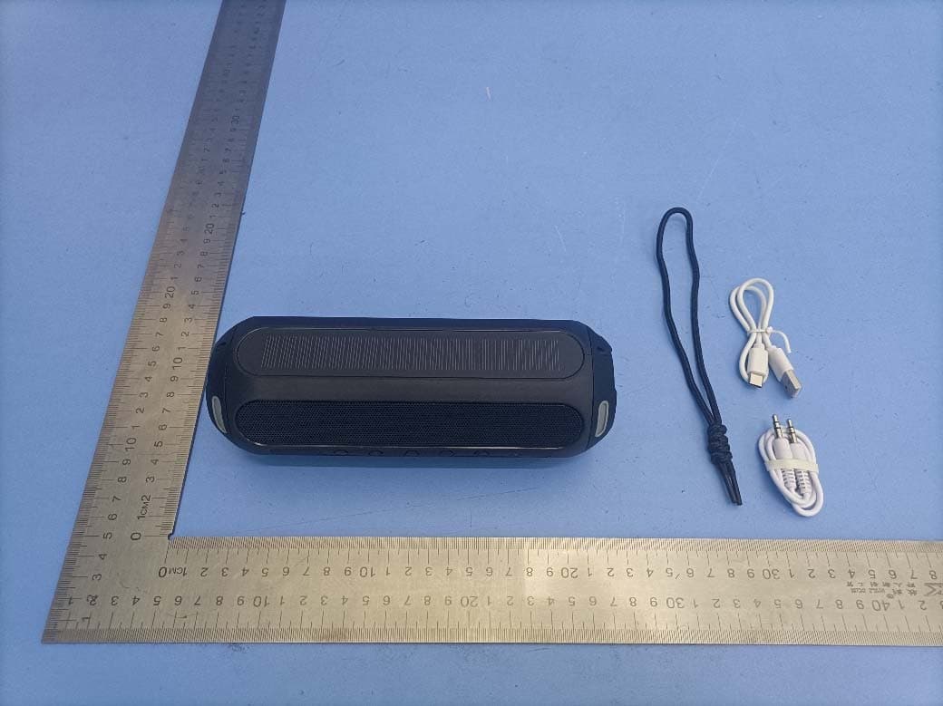
2AXR6-EL209
Nov 01, 2023Solar Bluetooth Speaker
Equipment Class
DTS - Digital Transmission System
2AXR6-EL203
May 16, 2021EARBUDS
Equipment Class
DXX - Part 15 Low Power Communication Device Transmitter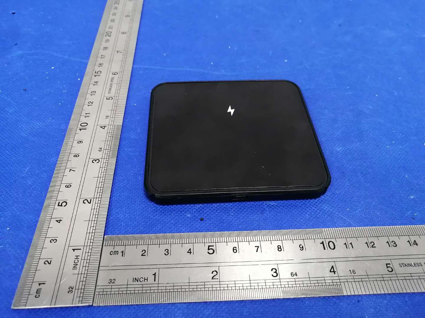
2AXR6-EL197
Oct 12, 202010W Wireless Charger Holder
Equipment Class
DCD - Part 15 Low Power Transmitter Below 1705 kHz