2AXUU1405Bluetooth Speaker
SHENZHEN MOCLOUD TECHNOLOGY CO., LTD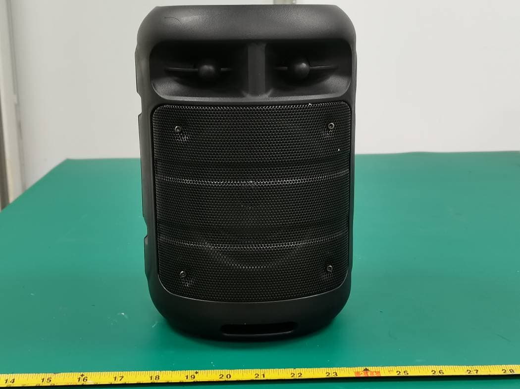
Click to zoom
Application Details
- Equipment Class
- DSS - Part 15 Spread Spectrum Transmitter
- Date of Grant
- Jun 30, 2021
- Application Purpose
- Original Equipment
- Date of Application
- Jun 30, 2021
- Equipment Note
- Bluetooth Speaker
- Frequency Range
- 2402.00000000 - 2480.00000000
- Country
- China
Documents & Files
Document Text
Text extracted from the exhibit documents filed with the FCC. Open a document above to read the original.
Users Manual
Portable Wireless Speaker MC-1405LH FEATURES: 1. Outdoor HiFi Wireless BT Speaker with 4inch subwoofer. 2. Output power is strong, you can enjoy your music anywhere 3. BT with lower power consumption and over 10m meters operating range. 4. Support USB and Micro-SD card and AUX and TWS function. 5. Support wired microphone give you experience the singer's feeling. 6. Colorful LED lights looks more beautiful. 7. With handle, easy to take out, wherever beach, garden, party, outskirts etc. SPECIFICATION: Speaker Type 4inch POWER WATTS/RMS Power 10W HERTZ /Frequency Response 150Hz - 18KHz Signal to Noise Ratio ≥80dB Woofer Full Range Frequency Speaker Tweeter Input Specs DC 5V, Output Voltage 3.7V Battery 1500mAh Ilunimation LED Flashlight Connections BT/Micro SD/FM/USB/AUX/MIC MANUAL 1. BT Mode: a) BT with lower power consumption and over 10m meters operating range. b) The “BLUE” character flashes into the pairing state, open the phone BT, search for the device name, click the device name to confirm and then connect. After the connection is successful, “BLUE” is always on, and the speaker sends a pairing success tone. 2. TF/Micro SD Card Mode: a) When the speaker is not plugged into the TF card device, it will boot into the BT mode. Inserting the TF card speaker will automatically detect the TF card playback mode. If the speaker has a TF card device, it will enter the TF card mode directly after booting. 3. U Disk Mode: a) When the speaker is not plugged into the U disk, it will boot into the BT mode. Inserting the U disk, speaker will automatically detect the USB playback mode. If the speaker has a U disk, it will enter the TF card mode directly after booting. 4. FM Mode: a) Press the button ‘MODE’, enter into FM mode. FM Frequency is 87.5Hz – 108.0MHz. b) This speaker has a built-in radio antenna, needn’t an external antenna. 5. AUX Mode: a) Plug one end of the 3.5MM audio cable into the speaker AUX jack, the speaker will automatically detect the AUX mode, and the other 3.5MM plug is connected to the phone or computer. 6. MIC FUNCTION: a) In the power-on mode, plug in the wired microphone, begin to work. (Note: turn on the button of wired microphone before using.) 7. CHARGING: a) Plug the USB cable into the speaker to connect to the 5V charger or computer to charge for inside Li-battery. b) The item has a red light on the charging indicator. When charging, the indicator light is on. When it is full, the indicator light is off. 8. Low-power protection: When the speaker detects that the built-in battery voltage is lower than 3.3V, it will emit a low-power alarm sound. When the battery voltage is lower than 3.1V, the speaker will automatically shut down. 9. Mode cycle: Press ‘MODE’ button to switch USB→TF→BT→FM→AUX. 10. LED flash light:Press ‘LED’ button to change LED effects. 11. TWS Function:Use your mobile phone connect one BT speaker successfully firstly, Under BT mode, long press MODE button of another BT speaker to enter into TWS pairing. FCC WARNING: This equipment has been tested and found to comply with the limits for a Class B digital device, pursuant to part 15 of the FCC Rules. These limits are designed to provide reasonable protection against harmful interference in a residential installation. This equipment generates uses and can radiate radio frequency energy and, if not installed and used in accordance with the instructions, may cause harmful interference to radio communications. However, there is no guarantee that interference will not occur in a particular installation. If this equipment does cause harmful interference to radio or television reception, which can be determined by turning the equipment off and on, the user is encouraged to try to correct the interference by one or more of the following measures: —Reorient or relocate the receiving antenna. —Increase the separation between the equipment and receiver. —Connect the equipment into an outlet on a circuit different from that to which the receiver is connected. —Consult the dealer or an experienced radio/TV technician for help. Any Changes or modifications not expressly approved by the party responsible for compliance could void the user's authority to operate the equipment. This device complies with part 15 of the FCC Rules. Operation is subject to the following two conditions: (1) This device may not cause harmful interference, and (2) this device must accept any interference received, including interference that may cause undesired operation. FCC Radiation Exposure Statement: This equipment complies with FCC radiation exposure limits set forth for an uncontrolled environment.
External Photos
Bay Area Compliance Laboratories Corp. (Shenzhen) Project No.: SZXX1210507-15799E-RF Page 1 of 4 EXHIBIT B - EUT EXTERNAL PHOTOGRAPHS Bay Area Compliance Laboratories Corp. (Shenzhen) Project No.: SZXX1210507-15799E-RF Page 2 of 4 Bay Area Compliance Laboratories Corp. (Shenzhen) Project No.: SZXX1210507-15799E-RF Page 3 of 4 Bay Area Compliance Laboratories Corp. (Shenzhen) Project No.: SZXX1210507-15799E-RF Page 4 of 4
ID Label/Location Info
Bay Area Compliance Laboratories Corp. (Shenzhen) Project No.: SZXX1210507-15799E-RF EXHIBIT A - FCC ID LABEL AND LOCATION FCC ID Label FCC ID Label Location Information The label shown shall be permanently affixed at a conspicuous location on the device and be readily visible to the user at the time purchase (Labeling requirements per 2.925)
Internal Photos
Bay Area Compliance Laboratories Corp. (Shenzhen) Project No.: SZXX1210507-15799E-RF Page 1 of 6 EXHIBIT C - EUT INTERNAL PHOTOGRAPHS Bay Area Compliance Laboratories Corp. (Shenzhen) Project No.: SZXX1210507-15799E-RF Page 2 of 6 Bay Area Compliance Laboratories Corp. (Shenzhen) Project No.: SZXX1210507-15799E-RF Page 3 of 6 Bay Area Compliance Laboratories Corp. (Shenzhen) Project No.: SZXX1210507-15799E-RF Page 4 of 6 Bay Area Compliance Laboratories Corp. (Shenzhen) Project No.: SZXX1210507-15799E-RF Page 5 of 6 Bay Area Compliance Laboratories Corp. (Shenzhen) Project No.: SZXX1210507-15799E-RF Page 6 of 6 BT Antenna
Test Report
Note: This report may contain data that are not covered by the A2LA accreditation and are marked with an asterisk “★”. BACL is not responsible for the authenticity of any test data provided by the applicant. Data included from the applicant that may affect test results are marked with an asterisk ’*’. Customer model name, addresses, names, trademarks etc. are not considered data. This report cannot be reproduced except in full, without prior written approval of the Company. Unless otherwise stated the results shown in this test report refer only to the sample(s) tested. This report is valid only with a valid digital signature. The digital signature may be available only under the Adobe software above version 7.0. FCC PART 15.247 TEST REPORT For SHENZHEN MOCLOUD TECHNOLOGY CO., LTD Rm 1401-02, Huatong Bldg., Ganli 2nd Road, Jihua Town, Longgang Dist., Shenzhen, China FCC ID: 2AXUU1405 Report Type: Original Report Product Type: Bluetooth Speaker Re port Number: SZXX1210507-15799E-00 Re port Date: 2021-06-10 Reviewed B y: Jacob Kong RF Engineer Prepared By: Bay Area Compliance Laboratories Corp. (Shenzhen) 5F(B-West) ,6F,7F,the 3rd Phase of Wan Li Industrial Building D,Shihua Rd, FuTian Free Trade Zone, Shenzhen, China Tel: +86-755-33320018 Fax: +86-755-33320008 www.baclcorp. com.cn Bay Area Compliance Laboratories Corp. (Shenzhen) Report No.: SZXX1210507-15799E-00 FCC Part 15.247 Page 2 of 56 TABLE OF CONTENTS GENERAL INFORMATION ....................................................................................................................................... 4 PRODUCT DESCRIPTION FOR EQUIPMENT UNDER TEST (EUT) ..................................................................................... 4 OBJECTIVE ................................................................................................................................................................... 4 TEST METHODOLOGY .................................................................................................................................................. 4 MEASUREMENT UNCERTAINTY .................................................................................................................................... 5 TEST FACILITY ............................................................................................................................................................. 5 SYSTEM TEST CONFIGURATION .......................................................................................................................... 6 DESCRIPTION OF TEST CONFIGURATION ...................................................................................................................... 6 EUT EXERCISE SOFTWARE .......................................................................................................................................... 6 SPECIAL ACCESSORIES ................................................................................................................................................. 6 EQUIPMENT MODIFICATIONS ....................................................................................................................................... 6 SUPPORT EQUIPMENT LIST AND DETAILS .................................................................................................................... 6 EXTERNAL I/O CABLE .................................................................................................................................................. 6 BLOCK DIAGRAM OF TEST SETUP ................................................................................................................................ 7 SUMMARY OF TEST RESULTS ............................................................................................................................... 8 TEST EQUIPMENT LIST ........................................................................................................................................... 9 FCC §15.247 (i) & §2.1091- MAXIMUM PERMISSIBLE EXPOSURE (MPE) ........................................................ 10 APPLICABLE STANDARD ............................................................................................................................................ 10 RESULT ...................................................................................................................................................................... 10 FCC §15.203 – ANTENNA REQUIREMENT .......................................................................................................... 11 APPLICABLE STANDARD ............................................................................................................................................ 11 ANTENNA CONNECTOR CONSTRUCTION .................................................................................................................... 11 FCC §15.207 (a) – AC LINE CONDUCTED EMISSIONS ..................................................................................... 12 APPLICABLE STANDARD ............................................................................................................................................ 12 EUT SETUP ................................................................................................................................................................ 12 EMI TEST RECEIVER SETUP ....................................................................................................................................... 12 TEST PROCEDURE ...................................................................................................................................................... 12 CORRECTED FACTOR & MARGIN CALCULATION ....................................................................................................... 13 TEST DATA ......................................................................................................................…
Text truncated - open the document above for the full version.
Test Setup Photos
Bay Area Compliance Laboratories Corp. (Shenzhen) Project No.: SZXX1210507-15799E-RF EXHIBIT D - TEST SETUP PHOTOGRAPHS Conducted Emissions - Front View Conducted Emissions - Side View Bay Area Compliance Laboratories Corp. (Shenzhen) Project No.: SZXX1210507-15799E-RF Radiated Emissions View (Below 1 GHz) Radiated Emissions View (Above 1 GHz)
Contact Information
Applicant
Robin Liu(International Sales Director)
Test Firm
Bay Area Compliance Laboratories Corp. (Shenzhen)Well Wang
[email protected]+86 (0) 755 33320018
Technical Specifications
| # | Rule Parts | Frequency Range | Power Output |
|---|---|---|---|
| 1 | 15C | 2.40 GHz - 2.48 GHz | 1.00 mW |
Other Applications from SHENZHEN MOCLOUD TECHNOLOGY CO., LTD
2AXUU621-515L
Jul 10, 2023SPEAKER
Equipment Class
DSS - Part 15 Spread Spectrum Transmitter
2AXUU8919-8920
Jul 09, 2023SPEAKER
Equipment Class
DSS - Part 15 Spread Spectrum Transmitter
2AXUUMPD611
Jul 09, 2023SPEAKER
Equipment Class
DSS - Part 15 Spread Spectrum Transmitter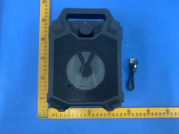
2AXUUMPD414L
Jul 06, 2023SPEAKER
Equipment Class
DSS - Part 15 Spread Spectrum Transmitter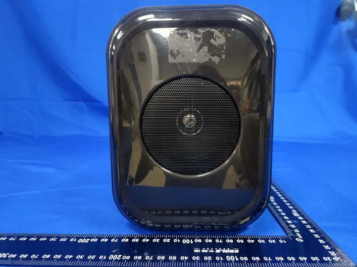
2AXUU-SPKR-JAMIN
Feb 16, 2023Bluetooth Speaker
Equipment Class
DSS - Part 15 Spread Spectrum Transmitter