2AXUUMPD414LSPEAKER
SHENZHEN MOCLOUD TECHNOLOGY CO., LTD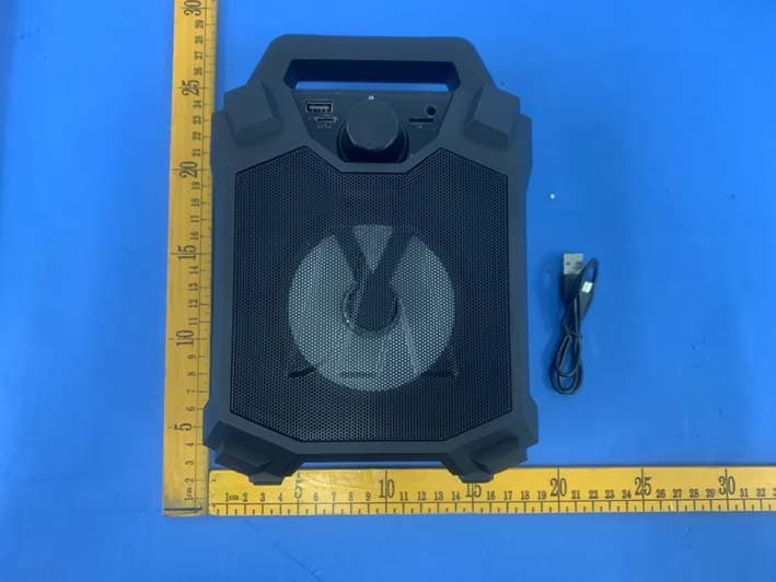
Click to zoom
Application Details
- Equipment Class
- DSS - Part 15 Spread Spectrum Transmitter
- Date of Grant
- Jul 06, 2023
- Application Purpose
- Original Equipment
- Date of Application
- Jul 06, 2023
- Equipment Note
- SPEAKER
- Frequency Range
- 2402.00000000 - 2480.00000000
- Country
- China
Documents & Files
Document Text
Text extracted from the exhibit documents filed with the FCC. Open a document above to read the original.
Users Manual
INSTRUCTIONS Output Power: 5W SNR:80dB THD:10% Battery:Built-in 1200 mAh rechargeable battery Power supplied:Power adapter 5.0V/1A Loudspeaker:4 inch x 1(External diameter 102mm)magnetic resistant 2 ohms PECIFICATIONS MPD414L WARNINGS: DEVICE FEATURES 1. Do not allow water to spill onto the surface or into the product 2. Unless the relevant regulatory instructed or has been directed by a person whom responsible for thesafety of the products they use,otherwise the product is not available for the person with body weakforce,or there is a lack of sensory capabilities persons(including children) 3. This product is not intended for using by childrenplease take care of children,do not let them play withthe product . 4. If the product surface is damaged or the case of mechanical or electronic equipment malfunction,do notuse this product,please contact with our service center.5. Do not shake or up-down dumped about this product. 6. Do not place the product immersed in water. 7. Do not place the product in light exposure to the location,to be placed in a dry and ventilate place 8. Do not place heavy objects on the product. Thank you for choosing our products! 1.Product dimensions:8.86"H x 6.22"W x 4.02"D 2.BT,wireless stream music from any BT-enabled devices such as mobile phone and notebook. 3.Built-in MP3 digital decoder for decoding and playing MP3 files.It brings you perfect sound quality 4.External TF card and USB socket to enjoy music. 5.With a mini control button for volume adjustment,easy to operate. 6.Micro DC 5V charging,supply with charging cable. 7.1200 mAh rechargeable battery. 8.FM digital radio(87MHZ-108MHZ),listen to the latest news and music. 9.Able to connect to any audio output equipment,such as mobile phones/MP3/MP4/laptops,etc. 10.Aux:AUX IN can connect to PC,mp3,Phone,or other aux facilities. 1.M button:Shortly pressing for switching among BT ,FM,Aux in ,TF Card,USB modes.Long pressing for turning off/on the LED light. 2. |◄◄ Shortly pressing to play the previous music under BT,TF Card,and USB modes.Shortly pressing to play previous radio station under FM mode.Long pressing to fast back under TF Card,and USB modes. 3. ►|| Shortly pressing for music play/pause.Long pressing for radio station automatic searching under FM mode. 4. ►►| Shortly pressing to play the next music under BT,TF Card,and USB modes.Shortly pressing to play next radio station under FM mode.Long pressing to fast forward under TF Card,and USB modes. 5.DC 5V:Charge Jack for built-in battery.When the DC 5V cable plugs in,the indicating LED lights up 6.Aux:AUX IN can connect to PC,mp3,Phone,or other aux facilities. 7.ON/OFF/Volume knob:Turning the knob to control volume up(Turn right) and down (Turn left).Turning the knob to the end of left to turn off and right to turn on the speaker. 8.USB Port:Support USB and can play MP3 format music in U disk. 9.TF card Port:Support TF CARD and can play MP3 format music in CARD. 1.How to connect to BT: When you turn on the speaker, it should already be on the BT mode. Please go on your smart device or cell phone and search for the BT connections. You should seem, MPD414L. Please select it and you will be connected and ready to enjoy the tunes. Short pressing the |◄◄ button to play last music. Short pressing the ►►| button to play next music. Short pressing the ►|| /SCAN button to play/pause music Twist the knob to control volume up(Turn right) and down (Turn left). 2.How to pair two speakers with the TWS function: Turn on speakers,double press the “►||” button on one of the speakers. And then an indication voice would sound.Speakers would enter TWS mode in 1-3 seconds.Two speakers could be connected with a same BT device and then play music together.When double press the “ ►||” button again to cancel the TWS function. 3.Radio function: Shortly press the M button and switch to Radio mode. Long pressing the ►|| button for station automatic searching.(Automatic searching will be finished in 2-5 minutes.) Short pressing the |◄◄ button to play last station. Short pressing the ►►| button to play next station. Twist the knob to control volume up(Turn right) and down (Turn left). FUNCTION 1 X MPD414L 1 X Type C Charging cable 1 X User Manual FCC Caution: Any Changes or modifications not expressly approved by the party responsible for compliance could void the user's authority to operate the equipment. This device complies with part 15 of the FCC Rules. Operation is subject to the following two conditions: (1) This device may not cause harmful interference, and (2) this device must accept any interference received, including interference that may cause undesired operation. IMPORTANT NOTE: Note: This equipment has been tested and found to comply with the limits for a Class B digital device, pursuant to part 15 of the FCC Rules. These limits are designed to provide reasonable protection against harmful interference in a residential installation. This equipment generates, uses and can radiate radio frequency energy and, if not installed and used in accordance with the instructions, may cause harmful interference to radio communications. However, there is no guarantee that interference will not occur in a particular installation. If this equipment does cause harmful interference to radio or television reception, which can be determined by turning the equipment off and on, the user is encouraged to try to correct the interference by one or more of the following measures: —Reorient or relocate the receiving antenna. —Increase the separation between the equipment and receiver. —Connect the equipment into an outlet on a circuit different from that to which the receiver is connected. —Consult the dealer or an experienced radio/TV technician for help. FCC Radiation Exposure Statement: This equipment complies with FCC radiation exposure limits set forth for an uncontrolled environment. This equipment should be installed and operated with minimum distance 20cm between the radiator& your body.
External Photos
Shenzhen Accurate Technology Co., Ltd. Project No.: RA230602-31236E-RF External Photos Page 1 of 4 External Photos Shenzhen Accurate Technology Co., Ltd. Project No.: RA230602-31236E-RF External Photos Page 2 of 4 Shenzhen Accurate Technology Co., Ltd. Project No.: RA230602-31236E-RF External Photos Page 3 of 4 Shenzhen Accurate Technology Co., Ltd. Project No.: RA230602-31236E-RF External Photos Page 4 of 4
ID Label/Location Info
Shenzhen Accurate Technology Co., Ltd. Report No.: RA230602-31236E-RF FCC ID Label EXHIBITA-FCC ID LABEL AND LOCATION FCC ID Label Location Information The label shown shall be permanently affixed at a conspicuous location on the device and be readily visible to the time purchase (Labeling requirements per 2.295)
Internal Photos
Shenzhen Accurate Technology Co., Ltd. Project No.: RA230602-31236E-RF Internal Photos Page 1 of 5 Internal Photos Shenzhen Accurate Technology Co., Ltd. Project No.: RA230602-31236E-RF Internal Photos Page 2 of 5 Shenzhen Accurate Technology Co., Ltd. Project No.: RA230602-31236E-RF Internal Photos Page 3 of 5 Shenzhen Accurate Technology Co., Ltd. Project No.: RA230602-31236E-RF Internal Photos Page 4 of 5 Shenzhen Accurate Technology Co., Ltd. Project No.: RA230602-31236E-RF Internal Photos Page 5 of 5 ANT
RF Exposure Info
Shenzhen Accurate Technology Co., Ltd. Report No.: RA230602-31236E-RF Version 7: 2023-01-30 Page 11 of 63 FCC-RF FCC §1.1307 (b) – RF EXPOSURE Applicable Standard According to KDB 447498 D04 Interim General RF Exposure Guidance v01, clause 2.1.4 –MPE-Based Exemption: An alternative to the SAR-based exemption is provided in § 1.1307(b)(3)(i)(C), for a much wider frequency range, from 300 kHz to 100 GHz, applicable for separation distances greater or equal to λ/2π, where λ is the free-space operating wavelength in meters. The MPE-based test exemption condition is in terms of ERP, defined as the product of the maximum antenna gain and the delivered maximum time-averaged power. For this case, a RF source is an RF exempt device if its ERP (watts) is no more than a frequency-dependent value, as detailed tabular form in Appendix B. These limits have been derived based on the basic specifications on Maximum Permissible Exposure (MPE) considered for the FCC rules in § 1.1310(e)(1). Table to § 1.1307(b)(3)(i)(C) - Single RF Sources Subject to Routine Environmental Evaluation f = frequency in MHz; R = minimum separation distance from the body of a nearby person (appropriate units, e.g., m); Test Result For worst case: Mode Frequency Range (MHz) Tune-up Output Power Antenna Gain ERP Evaluation Distance (cm) MPE-Based Exemption Threshold (mW) (dBm) (mW) (dBi) (dBd) (dBm) (mW) BDR/EDR 2402-2480 3.5 2.24 -0.68 -2.83 0.67 1.17 20 768 Note 1: The tune-up power was declared by the applicant. Note 2: 0dBd=2.15dBi. To maintain compliance with the FCC’s RF exposure guidelines, place the equipment at least 20cm from nearby persons. Result: Compliant.
Test Report
Antenna Specification Summary ITEM ANT SPEC Model Name 2.4G ANT Center Horizontal Vertical 2400MHz 2450MHz 2500MHz 2400MHz 2450MHz 2500MHz Frequency -1.28 dBi -0.94 dBi -0.68dBi -4.42 dBi -2.46 dBi -1.86 dBi MAX. Gain -0.68dBi Polarization Horizontal and Vertical Azimuth Beam Omni-directional Pattern Impedance 50 Ohm Antenna Length 14.5mm Antenna Type PCB Antenna Manufacture Shenzhen Yuhao Senda Technology Co., LTD 3rd Floor, Building 4, Xiyuantong Industrial Park, Zikeng Village,Shiyan Street, Bao'an District, Shenzhen City, Guangdong Province, China Antenna Photo & Length (mm) d Bi ( G a i n Radiation Pattems ) -0.68 -1.02 -1.53 -2.36 -4.01 -6.23 -8.56 -10.36 -13.45 -16.58 -18.56 -21.89 -23.47 -25.69
Test Report
Note: This report may contain data that are not covered by the A2LA accreditation and are marked with an asterisk “★”. Shenzhen Accurate Technology Co., Ltd. is not responsible for the authenticity of any test data provided by the applicant. Data included from the applicant that may affect test results are marked with an asterisk ’*’. Customer model name, addresses, names, trademarks etc. are not considered data. This report cannot be reproduced except in full, without prior written approval of the Company. Unless otherwise stated the results shown in this test report refer only to the sample(s) tested. This report is valid only with a valid digital signature. The digital signature may be available only under the Adobe software above version 7.0. Shenzhen Accurate Technology Co., Ltd. 1/F., Building A, Changyuan New Material Port, Science & Industry Park, Nanshan District, Shenzhen, Guangdong, P.R. China Tel: +86 755-26503290 Fax: +86 755-26503290 Web: www.atc-lab.com Version 7: 2023-01-30 Page 1 of 63 FCC-RF TEST REPORT Applicant Name : SHENZHEN MOCLOUD TECHNOLOGY CO., LTD Address : Rm 1401-02, Huatong Bldg., Ganli 2nd Road, Jihua Town, Longgang Dist. Shenzhen, China Report Number : RA230602-31236E-RF FCC ID: 2AXUUMPD414L Test Standard (s) FCC PART 15.247 Sample Description Product Type: SPEAKER Model No.: MPD414L Trade Mark: Date Received: 2023-06-02 Date of Test: 2023-06-05 to 2023-06-08 Report Date: 2023-06-14 Test Result: Pass* * In the configuration tested, the EUT complied with the standards above. Prepared and Checked By: Approved By: Dave Liang Candy Li EMC Engineer EMC Engineer Shenzhen Accurate Technology Co., Ltd. Report No.: RA230602-31236E-RF Version 7: 2023-01-30 Page 2 of 63 FCC-RF TABLE OF CONTENTS DOCUMENT REVISION HISTORY ......................................................................................................................... 4 GENERAL INFORMATION ....................................................................................................................................... 5 PRODUCT DESCRIPTION FOR EQUIPMENT UNDER TEST (EUT) ..................................................................................... 5 OBJECTIVE ................................................................................................................................................................... 5 TEST METHODOLOGY .................................................................................................................................................. 5 MEASUREMENT UNCERTAINTY .................................................................................................................................... 6 TEST FACILITY ............................................................................................................................................................. 6 SYSTEM TEST CONFIGURATION .......................................................................................................................... 7 DESCRIPTION OF TEST CONFIGURATION ...................................................................................................................... 7 EUT EXERCISE SOFTWARE .......................................................................................................................................... 7 SPECIAL ACCESSORIES ................................................................................................................................................. 7 EQUIPMENT MODIFICATIONS ....................................................................................................................................... 7 SUPPORT EQUIPMENT LIST AND DETAILS .................................................................................................................... 7 EXTERNAL I/O CABLE .................................................................................................................................................. 7 BLOCK DIAGRAM OF TEST SETUP ................................................................................................................................ 8 SUMMARY OF TEST RESULTS ............................................................................................................................... 9 TEST EQUIPMENT LIST ......................................................................................................................................... 10 FCC §1.1307 (b) – RF EXPOSURE ........................................................................................................................... 11 FCC §15.203 – ANTENNA REQUIREMENT .......................................................................................................... 12 APPLICABLE STANDARD ............................................................................................................................................ 12 ANTENNA CONNECTOR CONSTRUCTION .................................................................................................................... 12 FCC §15.207 (a) – AC LINE CONDUCTED EMISSIONS ..................................................................................... 13 APPLICABLE STANDARD ............................................................................................................................................ 13 EUT SETUP ................................................................................................................................................................ 13 EMI TEST RECEIVER SETUP ....................................................................................................................................... 13 TEST PROCEDURE ...................................................................................................................................................... 14 FACTOR & OVER LIMIT CALCULATION .....................................................................................…
Text truncated - open the document above for the full version.
Test Report
Shenzhen Accurate Technology Co., Ltd. Report No.: RA230602-31236E-RF Version 7: 2023-01-30 Page 33 of 63 FCC-RF 20 dB EMISSION BANDWIDTH_2DH5 _Ant1_2441 99% OCCUPIED BANDWIDTH_2DH5 _Ant1_2441 Shenzhen Accurate Technology Co., Ltd. Report No.: RA230602-31236E-RF Version 7: 2023-01-30 Page 34 of 63 FCC-RF 20 dB EMISSION BANDWIDTH _2DH5_Ant1_2480 99% OCCUPIED BANDWIDTH _2DH5_Ant1_2480 Shenzhen Accurate Technology Co., Ltd. Report No.: RA230602-31236E-RF Version 7: 2023-01-30 Page 35 of 63 FCC-RF 20 dB EMISSION BANDWIDTH _3DH5_Ant1_2402 99% OCCUPIED BANDWIDTH _3DH5_Ant1_2402 Shenzhen Accurate Technology Co., Ltd. Report No.: RA230602-31236E-RF Version 7: 2023-01-30 Page 36 of 63 FCC-RF 20 dB EMISSION BANDWIDTH _3DH5_Ant1_2441 99% OCCUPIED BANDWIDTH _3DH5_Ant1_2441 Shenzhen Accurate Technology Co., Ltd. Report No.: RA230602-31236E-RF Version 7: 2023-01-30 Page 37 of 63 FCC-RF 20 dB EMISSION BANDWIDTH _3DH5_Ant1_2480 99% OCCUPIED BANDWIDTH _3DH5_Ant1_2480 Shenzhen Accurate Technology Co., Ltd. Report No.: RA230602-31236E-RF Version 7: 2023-01-30 Page 38 of 63 FCC-RF FCC §15.247(a) (1) (iii)-QUANTITY OF HOPPING CHANNEL TEST Applicable Standard Frequency hopping systems in the 2400–2483.5 MHz band shall use at least 15 channels. The average time of occupancy on any channel shall not be greater than 0.4 seconds within a period of 0.4 seconds multiplied by the number of hopping channels employed. Frequency hopping systems may avoid or suppress transmissions on a particular hopping frequency provided that a minimum of 15 channels are used. Test Procedure According to ANSI C63.10-2013, section 7.8.3 1. Check the calibration of the measuring instrument (SA) using either an internal calibrator or a known signal from an external generator. 2. Set the EUT in hopping mode from first channel to last. 3. By using the max-h old function record the quantity of the channel. Test Data Environmental Conditions Temperature: 25°C Relative Humidity: 47% ATM Pressure: 101.0kPa The testing was performed by Matt Liang on 2023-06-08. EUT operation mode: Transmitting Test Result: Compliant. Please refer to the below table and plots: Test Mode Antenna Channel Result[Num] Limit[Num] Verdict DH5 Ant1 Hop 79 >=15 PASS 2DH5 Ant1 Hop 79 >=15 PASS 3DH5 Ant1 Hop 79 >=15 PASS Spectrum Analyzer EUT Open Switch and Control Unit Attenuator Shenzhen Accurate Technology Co., Ltd. Report No.: RA230602-31236E-RF Version 7: 2023-01-30 Page 39 of 63 FCC-RF DH5_Ant1_Hop 2DH5_Ant1_Hop Shenzhen Accurate Technology Co., Ltd. Report No.: RA230602-31236E-RF Version 7: 2023-01-30 Page 40 of 63 FCC-RF 3DH5_Ant1_Hop Shenzhen Accurate Technology Co., Ltd. Report No.: RA230602-31236E-RF Version 7: 2023-01-30 Page 41 of 63 FCC-RF FCC §15.247(a) (1) (iii) - TIME OF OCCUPANCY (DWELL TIME) Applicable Standard Frequency hopping systems in the 2400-2483.5 MHz shall use at least 15 channels. The average time of occupancy on any channel shall not be greater than 0.4 seconds within a period of 0.4 seconds multiplied by the number of hopping channels employed. Frequency hopping systems may avoid or suppress transmissions on a particular hopping frequency provided that a minimum of 15 channels are used. Test Procedure According to ANSI C63.10-2013, section 7.8.4 1. The EUT was worked in channel hopping. 2. Set the RBW to: 1MHz. 3. Set the VBW ≥ 3×RBW. 4. Set the span to 0Hz. 5. Detector = peak. 6. Sweep time = auto couple. 7. Trace mode = max hold. 8. Allow trace to fully stabilize. 9. Recorded the time of single pulses Test Data Environmental Conditions Temperature: 25°C Relative Humidity: 47% ATM Pressure: 101.0kPa The testing was performed by Matt Liang on 2023-06-08. EUT operation mode: Transmitting Test Result: Compliant. Please refer to the below table and plots: Test Mode Antenna Channel Burst Width [ms] Total Hops [Num] Result[s] Limit[s] Verdict DH1 Ant1 Hop 0.408 320 0.131 ≤0.4 PASS DH3 Ant1 Hop 1.656 160 0.265 ≤0.4 PASS DH5 Ant1 Hop 2.898 110 0.319 ≤0.4 PASS 2DH1 Ant1 Hop 0.418 330 0.138 ≤0.4 PASS 2DH3 Ant1 Hop 1.663 130 0.216 ≤0.4 PASS 2DH5 Ant1 Hop 2.902 120 0.348 ≤0.4 PASS 3DH1 Ant1 Hop 0.420 320 0.134 ≤0.4 PASS 3DH3 Ant1 Hop 1.661 170 0.282 ≤0.4 PASS 3DH5 Ant1 Hop 2.905 120 0.349 ≤0.4 PASS Note 1: A period time=0.4*79=31.6(s), Result=Burst Width*Total Hops Note 2: Total Hops =Hopping Number in 3.16s*10 Note 3: Hoping Number in 3.16s=Total of highest signals in 3.16s (Second high signals were other channel) Spectrum Analyzer EUT Open Switch and Control Unit Attenuator Shenzhen Accurate Technology Co., Ltd. Report No.: RA230602-31236E-RF Version 7: 2023-01-30 Page 42 of 63 FCC-RF DH1_Ant1_Hop Shenzhen Accurate Technology Co., Ltd. Report No.: RA230602-31236E-RF Version 7: 2023-01-30 Page 43 of 63 FCC-RF DH3_Ant1_Hop Shenzhen Accurate Technology Co., Ltd. Report No.: RA230602-31236E-RF Version 7: 2023-01-30 Page 44 of 63 FCC-RF DH5_Ant1_Hop Shenzhen Accurate Technology Co., Ltd. Report No.: RA230602-31236E-RF Version 7: 2023-01-30 Page 45 of 63 FCC-RF 2DH1_Ant1_Hop Shenzhen Accurate Technology Co., Ltd. Report No.: RA230602-31236E-RF Version 7: 2023-01-30 Page 46 of 63 FCC-RF 2DH3_Ant1_Hop Shenzhen Accurate Technology Co., Ltd. Report No.: RA230602-31236E-RF Version 7: 2023-01-30 Page 47 of 63 FCC-RF 2DH5_Ant1_Hop Shenzhen Accurate Technology Co., Ltd. Report No.: RA230602-31236E-RF Version 7: 2023-01-30 Page 48 of 63 FCC-RF 3DH1_Ant1_Hop Shenzhen Accurate Technology Co., Ltd. Report No.: RA230602-31236E-RF Version 7: 2023-01-30 Page 49 of 63 FCC-RF 3DH3_Ant1_Hop Shenzhen Accurate Technology Co., Ltd. Report No.: RA230602-31236E-RF Version 7: 2023-01-30 Page 50 of 63 FCC-RF 3DH5_Ant1_Hop Shenzhen Accurate Technology Co., Ltd. Report No.: RA230602-31236E-RF Version 7: 2023-01-30 Page 51 of 63 FCC-RF FCC §15.247(b) (1) - PEAK OUTPUT POWER MEASUREMENT Applicable Standard According to §15.247(b) (1), for frequency hopping systems operating in the 2400–2483.5 MHz band employing at least 75 non-overlapping hopping channels, and all frequency hopping s…
Text truncated - open the document above for the full version.
Test Setup Photos
Shenzhen Accurate Technology Co., Ltd. Project No.: RA230602-31236E-RF Test Photos Page 1 of 2 Photo of Power Line Conducted Emission Measurement Shenzhen Accurate Technology Co., Ltd. Project No.: RA230602-31236E-RF Test Photos Page 2 of 2 Radiated Spurious Emissions Test View (Below 1GHz) Radiated Spurious Emissions Test View (Above 1GHz)
Contact Information
Applicant
Robin Liu(International Sales Director)
Test Firm
Shenzhen Accurate Technology Co., Ltd.Lisa Zhang
[email protected]+86-755-26503290
Technical Specifications
| # | Rule Parts | Frequency Range | Power Output |
|---|---|---|---|
| 1 | 15C | 2.40 GHz - 2.48 GHz | 2.00 mW |
Other Applications from SHENZHEN MOCLOUD TECHNOLOGY CO., LTD
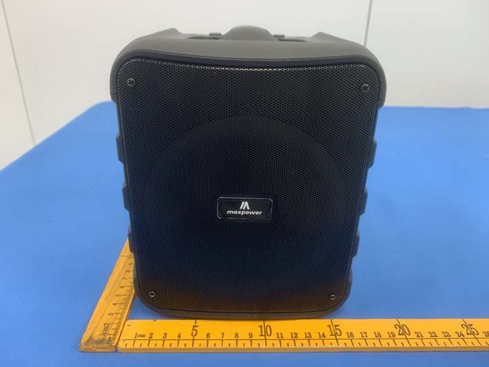
2AXUU621-515L
Jul 10, 2023SPEAKER
Equipment Class
DSS - Part 15 Spread Spectrum Transmitter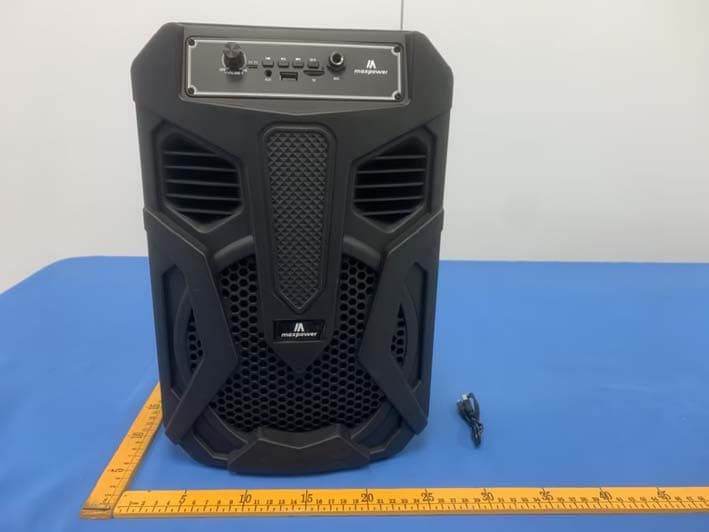
2AXUU8919-8920
Jul 09, 2023SPEAKER
Equipment Class
DSS - Part 15 Spread Spectrum Transmitter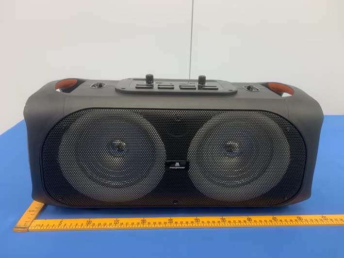
2AXUUMPD611
Jul 09, 2023SPEAKER
Equipment Class
DSS - Part 15 Spread Spectrum Transmitter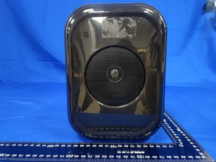
2AXUU-SPKR-JAMIN
Feb 16, 2023Bluetooth Speaker
Equipment Class
DSS - Part 15 Spread Spectrum Transmitter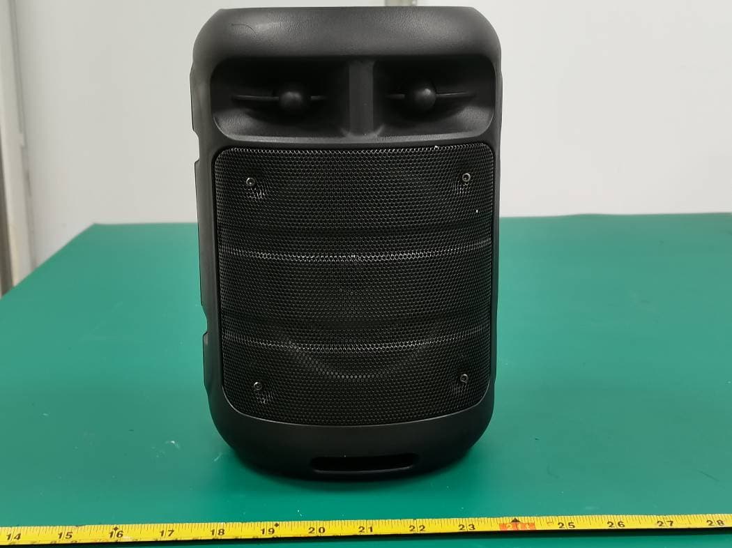
2AXUU1405
Jun 30, 2021Bluetooth Speaker
Equipment Class
DSS - Part 15 Spread Spectrum Transmitter