2AYCW-SOLOSMSANSmart cap for pen injectors
BIOCORP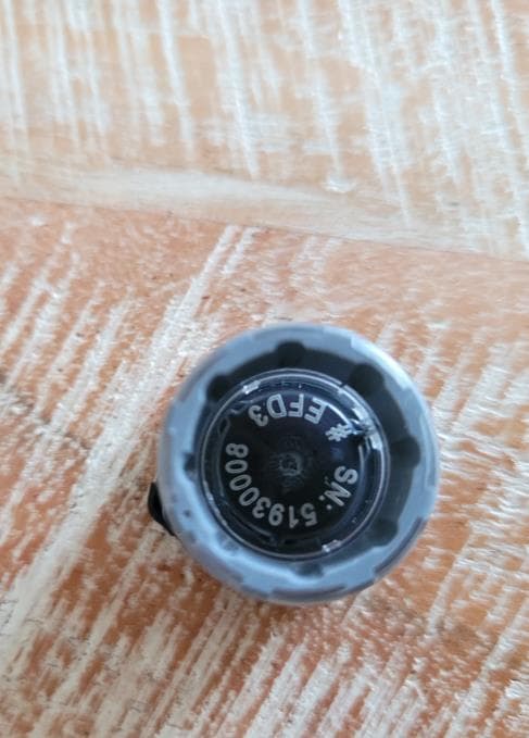
Click to zoom
Application Details
- Equipment Class
- DTS - Digital Transmission System
- Date of Grant
- Aug 08, 2024
- Application Purpose
- Original Equipment
- Date of Application
- Aug 08, 2024
- Equipment Note
- Smart cap for pen injectors
- Frequency Range
- 2402.00000000 - 2480.00000000
- Company
- BIOCORP
- Country
- France
Documents & Files
Document Text
Text extracted from the exhibit documents filed with the FCC. Open a document above to read the original.
Users Manual
pour SoloStar ® & DoubleStar ® Solosmart est prévu pour: • enregistrer la dose d’insuline injectée par un stylo à insuline pré-rempli SoloStar ® ou DoubleStar ® de Sano昀椀 ; • enregistrer la date et l’heure de chaque injection d’insuline ; • transmettre l’information concernant la dose, la date et l’heure de chaque injection à une application mobile compatible sur un téléphone intelligent, quand le dispositif y est connecté, utilisant la technologie Bluetooth. Le dispositif SoloSmart pour stylo à insuline est indiqué pour être utilisé par les patients dans les mêmes conditions d’utilisation que leur stylo à insuline compatible. Il n’existe aucune contre-indication connue à l’utilisation de SoloSmart pour ces patients. Indications Dans l’étui 1 SoloSmart1 cable USB 1 guide utilisateur NOTE : Le chargeur USB n’est pas fourni. Utilisez un chargeur secteur USB de classe II, avec sortie 5V et minimum 500mA. Apprendre à connaître SoloSmart PN : 0273971PN : 0373707 Votre stylo SoloStar et DoubleStar Bouton d’injection Sélection de dose SoloSmart Bouton Port de chargement micro-USB Voyant lumineux Corps Arêtes en caoutchouc Comment con昀椀gurer votre SoloSmart Allumer et charger le dispositif Connectez SoloSmart au câble USB fourni et connectez le câble à un chargeur secteur USB branché. Le dispositif va s’allumer. Monter SoloSmart sur votre stylo Appuyez fermement et maintenez le bouton du SoloSmart pendant au moins 5 secondes jusqu’à ce que le voyant devienne violet. Avant de faire votre injection, véri昀椀ez toujours que SoloSmart est en mode actif en appuyant et relâchant rapidement le bouton du SoloSmart. • Si le voyant devient vert puis s’éteint, SoloSmart est en mode actif et prêt à être utilisé pour l’injection. • Si le voyant ne s’allume pas après avoir appuyé et relâché le bouton du SoloSmart, cela signi昀椀e qu’il est en mode veille et nécessite d’être mis en mode actif avant de réaliser une injection. • Suivez l’étape 4 de la section « Comment con昀椀gurer votre SoloSmart » ci-dessus a昀椀n de mettre le dispositif en mode actif. Une fois que SoloSmart est en mode actif, il est prêt à être utilisé pour l’injection. Téléchargez une application compatible et jumelez-la avec SoloSmart < 10cm Avant d’utiliser votre SoloSmart, vous devez le jumeler avec une application mobile sur votre téléphone intelligent. Mettre SoloSmart en mode actif Injecter une dose avec SoloSmart monté sur votre stylo 1234 SoloSmart vous permet de faire vos injections avec votre stylo comme vous le faites habituellement. Référez-vous au mode d’emploi de votre stylo pour le test de sécurité et les instructions d’injection. Note : Les tests de sécurité réalisés pour véri昀椀er l’écoulement de l’insuline seront automatiquement détectés et enregistrés par SoloSmart. Véri昀椀ez votre application mobile pour correctement identi昀椀er les tests de sécurité effectués. La batterie est faible. Chargez SoloSmart en suivant les instructions de la section « Charger SoloSmart ». Chargez la batterie pendant au moins 2 heures pour une charge complète. Ne réalisez pas d’injection avec SoloSmart lorsqu’il est en charge. Erreur : le voyant rouge 昀椀xe s’af昀椀che lorsque SoloSmart est dans un statut d’erreur et nécessite d’être réinitialisé. Suivez les instructions de la section « Réinitialisation de SoloSmart » au verso de ces instructions pour réinitialiser SoloSmart. Voyant orangeVoyant rouge 昀椀xe Dépannage GUIDE UTILISATEUR Pour vous aider à suivre vos injections d’insuline Arêtes surévelées Le dispositif est éteint lorsqu’il est expédié. Vous devrez allumer le dispositif et vous assurer qu’il est suf昀椀samment chargé avant utilisation. 1.1 1.3 1.2 Une fois jumelé, le voyant clignote en vert puis s’éteint SoloSmart se monte sur le bouton d’injection de votre stylo. Pour le monter, suivez attentivement les étapes suivantes. 2.1 2.3 2.2 Téléchargez l’application sur Google Play™ (Android) ou l’App Store ® (Apple). Jumeler SoloSmart en suivant les instructions de l’application pour : • Activer le Bluetooth sur votre téléphone intelligent (s’il n’est pas déjà activé) • Jumeler SoloSmart avec l’application Note : vous devez placer SoloSmart à moins de 10 centimètres de votre téléphone intelligent pendant le jumelage. A la 昀椀n de l’étape de jumelage, vous remarquerez que le voyant devient vert puis s’éteint. Une fois jumelé, votre SoloSmart entrera en mode veille et le voyant s’éteindra. Après le jumelage, suivez les instructions de l’application pour sélectionner le type d’insuline. Enfoncez SoloSmart sur le boîtier transparent jusqu’à ce que le bouton d’injection soit complètement recouvert. 3.1 3.3 3.2 4.1 4.2 Résumé Avant votre injection avec SoloSmart Lorsque vous faites vos injections avec SoloSmart, vous devez : Injecter votre dose en une seule poussée, sans changer la position du doigt ou de la main pendant l’injection. Garder le stylo stable et droit pendant l’injection. Appuyer fermement, continuellement au centre du bouton et non sur les bords. Après l’injection, gardez votre pouce appuyé sur le bouton d’injection jusqu’à ce que le voyant vert clignotant rapidement s’éteigne. La batterie de SoloSmart dure au moins 1 semaine sur une charge complète dans des conditions normales. Lorsque la batterie est faible, le voyant orange s’allume. Charger SoloSmart Tenez SoloSmart par le boîtier transparent. Des arêtes en caoutchouc peuvent être visibles à l’extérieur de SoloSmart. Placez SoloSmart sur le stylo de manière à ce que l’indicateur de dose du stylo se trouve entre les arêtes en caoutchouc de SoloSmart. Arêtes en caoutchouc Arêtes en caoutchouc Indicateur de dose Emboîté Maintenir appuyé jusqu’à ce que le voyant devienne violet Voyant vert après avoir relâché le bouton Puis, retirez votre doigt du bouton. Le voyant devient vert, signalant que le dispositif est désormais en mode actif. Note : Si le voyant ne devient pas violet, assurez-vous que SoloSmart est enfoncé complètement. Votre SoloSmart est maintenant prêt à l’emploi. Important : suivez la…
Text truncated - open the document above for the full version.
Users Manual
LEGEND: PLANT PM CODE: 0574317 -2 VERSION: 1.1 DIMENSIONS: 520x320 mm PAGE: 1/2 for SoloStar & DoubleStar SoloSmart is intended to: • record the increment injected by Sano昀椀 SoloStar or Sano昀椀 DoubleStar pen (insulin dose), • re cord the date and time of each insulin injection, • transmit information relating to the dose, time, and date of each injection to a compatible mobile application on a smartphone, when the device is connected to it, using Bluetooth technology. The SoloSmart injection pen adapter is intended to be used by patients in the same use environment as their compatible injection pen. There are no known contraindications to the use of SoloSmart for these patients. Intended use In the box SoloSmart x1 USB cable x1 User manual x1 NOTE: the USB charger is not included. Use a Class II USB wall charger, with output 5V and at least 500mA. Getting to know SoloSmart PN : 0273971 PN : 0373707 Your SoloStar ® / DoubleStar ® Pen Injection button Dose selector SoloSmart Button Micro-USB charging port Signal light Body Rubber ridges How to Setup Your SoloSmart Wake Up and Charge the Device Connect SoloSmart to the supplied USB cable and connect the cable to a powered USB wall charger. This will wake up the device. Let the device charge for at least 10 minutes before use. Unplug SoloSmart from the USB cable and then unplug the wall charger. When you are done, the SoloSmart signal light will turn blue indicating that the device is in pairing mode but not yet paired. Attach SoloSmart to your Pen To activate SoloSmart on the pen: Firmly press and hold the SoloSmart button down for at least 5 seconds until the light turns purple. Before you inject, always check that SoloSmart is in active mode by quickly pressing and releasing the SoloSmart button. • If the light turns green and then turns off, SoloSmart is in active mode and ready to be used for injection. • If the light does not turn on after pressing and releasing the SoloSmart button, SoloSmart is in standby mode and needs to be put into active mode before performing an injection. Follow Step 4 in the “How to Setup Your SoloSmart” section above to put the device into active mode. Once SoloSmart is in active mode it is ready to be used for injection. Download a Compatible App and Pair with SoloSmart < 10cm Before you can use your SoloSmart, you will need to pair it with a mobile application on your smartphone. Put SoloSmart into Active Mode Injecting a Dose with SoloSmart Attached to Your Pen 1 2 34 SoloSmart allows you to inject with your pen as you normally would. Refer to the Instructions for Use of your pen for the safety test (priming) and injection instructions. Note: Safety tests performed to check the insulin 昀氀ow (priming) will also be automatically detected and recorded by SoloSmart. Check your mobile application for correct identi昀椀cation of the safety tests performed. The battery is low. Charge SoloSmart following the instructions in the “Charging SoloSmart” section. Charge the battery for at least 2 hours for a full charge. Do not give an injection with SoloSmart while it is charging. Error: the solid red light will come on when SoloSmart is in an error state and needs to be reset. Follow the instructions in the “Resetting SoloSmart” section on the back side of these instructions to reset SoloSmart. Orange lightSolid red light Troubleshooting USER MANUAL Helping you keep track of your insulin injections Raised ridges The device is turned off when it is shipped. You will need to wake up the device and make sure it is charged enough before use. 1.1 1.3 1.2 Charge at Least 10 Minutes When paired light will 昀氀ash green then turn off SoloSmart attaches to the injection button of your pen. Carefully follow the steps below to attach it. 2.1 2.3 2.2 Download the application from Google Play™ (Android) or the App Store® (Apple). Pair SoloSmart by following the guidance in the App to: • Turn on your smartphone’s Bluetooth (if not already on). • Pair the SoloSmart with the App. Note: you must keep SoloSmart within 10 centimeters of the smartphone during pairing. At the end of the pairing step, you may notice the signal light turn green and then turn off. Once paired your SoloSmart will enter standby mode and the light will turn off. After pairing, follow the guidance in the app to select the insulin type. Push SoloSmart on the transparent housing until the injection button is completely covered. 3.1 3.3 3.2 4.1 4.2 OverviewBefore Injecting with SoloSmart When Injecting With SoloSmart You Must Do the Following Inject your dose in one single thrust, without changing 昀椀nger or hand position during the injection. Keep pen stable and straight while injecting. Press 昀椀rmly and continuously on the center of the button, and not at an angle. After injecting, keep your thumb held down on the injection button until the rapidly 昀氀ashing green light turns off. SoloSmart’s battery will last at least 1-week on a full charge under normal conditions. When the battery is low, the orange light will show. Charging SoloSmart Hold SoloSmart by the transparent housing. Rubber ridges can be seen on the outside of SoloSmart. Place SoloSmart on the pen so that the dose indicator of the pen is between the rubber ridges of SoloSmart. Rubber ridges Rubber ridges Dose indicator Flush mounted Hold until light turns purple, then release Green light after button release Then, lift your 昀椀nger from the button. The light will then turn green showing the device is now in active mode. Note: If the light does not turn purple make sure SoloSmart is pushed all the way down. Your SoloSmart is now ready to use. Important: Follow the “Injecting a Dose with SoloSmart Attached to Your Pen” section below when you give an injection. Hold down until rapidly 昀氀ashing green light turns off Turn Over: • Transfer • Reset • Indicator Lights • Cleaning Let the device charge until the green 昀氀ashing light turns off. (2 hours for a full charge). The light will turn off when fully charged. C…
Text truncated - open the document above for the full version.
Attestation Statements
V02072023 Federal Communications Commission Authorization and Evaluation Division 7435 Oakland Mills Road Columbia, MD 21046 USA Date: June 13, 2024 Ref: Attestation Statement Part 2.911(d)(7) Filing FCC ID: 2AYCW-SOLOSMSAN BIOCORP certifies that, as of the dates of this application, Americas Compliance Consulting LLC dba iCertifi “iCertifi” is our designated U.S. agent for service of process for the above referenced FCC ID. BIOCORP accepts to maintain an agent for no less than one year after the grantee has terminated all marketing and importation or the conclusion of any commission- related proceeding involving the equipment. iCertifi accepts, as of the date of the filing of the application, the obligation of the designated U.S. agent for service process for the above referenced FCC ID. Designated U.S. Agent Information: Name: Americas Compliance consulting, LLC dba iCertifi FCC FRN: 0033399411 Address: 2445 NE Division Street, Suite 202 Bend, OR 97703 United States Contact Person: Paul Preston Tel: 866-885-4575 Email: [email protected] Sincerely, BIOCORP FRN : 0030249189 Americas Compliance Consulting LLC dba iCertifi Alexia GARIN , VP Quality & Regulatory Affairs Paul Preston Signature June 13, 2024 07/24/2024
Attestation Statements
Rev 1/26/2023 Federal Communications Commission Authorization and Evaluation Division 7435 Oakland Mills Road Columbia, MD 21046 USA Date: July 23, 2024 Ref: Attestation Statements Part 2.911(d)(5)(i) Filing FCC ID: 2AYCW-SOLOSMSAN BIOCORP (“the applicant”) certifies that the equipment for which authorization is sought is not “covered” equipment prohibited from receiving an equipment authorization pursuant to section 2.903 of the FCC rules. Link: List of Equipment and Services Covered By Section 2 of The Secure Networks Act Sincerely, BIOCORP Alexia GARIN Signature: Rev 1/26/2023 Federal Communications Commission Authorization and Evaluation Division 7435 Oakland Mills Road Columbia, MD 21046 USA Date: July 23, 2024 Ref: Attestation Statements Part 2.911(d)(5)(ii) Filing FCC ID: 2AYCW-SOLOSMSAN BIOCORP (“the applicant”) certifies that, as of the date of the filing of the application, the applicant is not identified on the Covered List (as a specifically named entity or any of its subsidiaries or affiliates) as an entity producing “covered” equipment. Link: List of Equipment and Services Covered By Section 2 of The Secure Networks Act Sincerely, BIOCORP Alexia GARIN Signature:
Cover Letter(s)
Letter of Agency July 23, 2024 To: Federal Communications Commission 7435 Oakland Mills Road Columbia, MD 21046-1609 Timco Engineering, Inc. 13146 NW 86th Drive, Suite 400 Alachua, FL 32615- United States We, the undersigned BIOCORP hereby authorizes Majid MOURZAGH, LCIE SUD EST, to act on our behalf in all matters relating to all processes required for FCC certification of our devices. Any and all acts carried out by the above agent on our behalf shall have the same effects as acts of our own. This authorization is valid until: July 31, 2024 If you have any questions regarding this authorization, let us know please. Sincerely, Alexia GARIN Signature:
Cover Letter(s)
COVER LETTER BIOCORP – EFD3 FCC ID: 2AYCW-SOLOSMSAN July 23, 2024 This report concerns: File : Original Grant SubPart: SubPart 15C Equipment type : Smart cap for pen injectors Request issue of grant : __ Immediately upon completion of review ___ Defer grant per 47 CFR 0.457(d)(1)(ii) until ____ date _____. Company Name agrees to notify the Commission by _____date_____ of the intended date of announcement of the product so that the grant can be issued on that date. Confidentiality of grant : __ Applicant requests the existence of this grant to be kept confidential until ____date____. The announcement of this product before this date via freedom of information would be detrimental to Company Name, and therefore must be considered a business secret. Public announcement of this product will not be made prior to this date. (Max. 60 days after grant issued). Limits used : (check one) CISPR 22: ______ Part15: ______ Measurement procedure used is ANSI C63.4-2014 / C63.10-2013 unless another is specified. Other test procedure : ____________________________________________________ Application for verification Applicant for this device Prepared by : Majid MOURZAGH LCIE Sud-Est ZI Centr’Alp – 170, rue de Chatagnon 38430 MOIRANS - France Ph. : 33 4 76 07 36 36 Fax : 33 4 76 55 90 88 e-mail : [email protected] FRN : 0005-0971-18 Alexia GARIN BIOCORP ZI de Lavaur - La Bechade 63500 - ISSOIRE - France Ph. : +33 +33645620362 Fax : +33 / e-mail: [email protected] FRN : 0030249189 Signature : Signature : *Not to be filed with Equipment Authorization Branch of FCC unless requested Report format prepared by the Information Technology Industry Council (ITI) ESC-5 and reviewed by FCC staff in 1994
Cover Letter(s)
CONFIDENTIALITY REQUEST To: Federal Communications Commission Authorization and Evaluation Division 7435 Oakland Mills Road Columbia, MD 21046-1609 Cc: Timco Engineering, Inc. 13146 NW 86th Drive, Suite 400 Alachua, FL 32615- United States July 23, 2024 Subject: Confidentiality request FCC ID: 2AYCW-SOLOSMSAN BIOCORP requests, pursuant to 47CFR 0.457 and 0.459, post grant confidentiality for portions of the material contained in this application. The following document regarding this submission for FCC ID: 2AYCW-SOLOSMSAN shall be kept confidential: LONG-TERM CONFIDENTIALITY: 1. Block Diagram description of the equipment (file: Block Diagram - 2AYCW-SOLOSMSAN.pdf) 2. Operational description of the equipment (file: Operational Description -2AYCW-SOLOSMSAN.pdf) 3. Schematic Diagram of the equipment (file: Schematic -2AYCW-SOLOSMSAN.pdf) The above materials contain trade secrets and proprietary information not customarily released to the public. The public disclosure of these materials may be harmful to the applicant and provide unjustified benefits to its competitors. Permanent Confidentiality: The applicant requests the exhibits listed above as permanently confidential be permanently withheld from public review due to materials that contain trade secrets and proprietary information not customarily released to the public. The applicant understands that disclosure of this application and all accompanying documentation will not be made before the date of the Grant for this application. Sincerely, Responsible party: Alexia GARIN Title: VP Quality & Regulatory Affairs Signature:
External Photos
LCIE SUD EST Laboratoire de Moirans Z.I. Centr’Alp 170, Rue de Chatagnon 38430 MOIRANS – France Page 1/1 EXTERNAL PHOTOS OF EQUIPMENT IC: 26747-SOLOSMSAN FCC ID: 2AYCW-SOLOSMSAN
ID Label/Location Info
LCIE SUD EST Laboratoire de Moirans Z.I. Centr’Alp 170, Rue de Chatagnon 38430 MOIRANS - FRANCE Page 1/1 PRODUCT LABELING Label Label position on packaging
Internal Photos
LCIE SUD EST Laboratoire de Moirans Z.I. Centr’Alp 170, Rue de Chatagnon 38430 MOIRANS - FRANCE Page 1/1 INTERNAL PHOTOS OF EQUIPMENT IC: 26747-SOLOSMSAN RF Antenna FCC ID: 2AYCW-SOLOSMSAN
RF Exposure Info
LCIE SUD EST Laboratoire de Moirans Z.I. Centr’Alp 170, Rue de Chatagnon 38430 MOIRANS – FRANCE RF Exposure Considerations for FCC ID: 2AYCW-SOLOSMSAN Per FCC KDB 447498 D01 General RF Exposure Guidance v06 The 1-g and 10-g SAR test exclusion thresholds for 100 MHz to 6 GHz are based on source-based time-averaged maximum conducted output power of the RF channel requiring evaluation, adjusted for tune-up tolerance, and the minimum test separation distance required for the exposure conditions. The minimum test separation distance defined in 4.1 f) is determined by the smallest distance from the antenna and radiating structures or outer surface of the device, according to the host form factor, exposure conditions and platform requirements, to any part of the body or extremity of a user or bystander. Minimum test separation distance: 5 mm Step a) For 100 MHz to 6 GHz and test separation distances ≤ 50 mm The 1-g and 10-g SAR test exclusion thresholds are determined by the following: (max푝표푤푒푟표푓 푐ℎ푎푛푛푒푙 ( 푚푊 ) ) (min푡푒푠푡푠푒푝푎푟푎푡푖표푛 푑푖푠푡푎푛푐푒 ( 푚푚 ) ) × √ 푓 ( 퐺퐻푧 ) ≤3.0 푓표푟 1−푔 푆퐴푅 표푟 ≤7.5 푓표푟 10−푔 푒푥푡푟푒푚푖푡푦 푆퐴푅 Where: ▪ f(GHz) is the RF channel transmit frequency in GHz ▪ Power and distance are rounded to the nearest mW and mm before calculation31 ▪ The result is rounded to one decimal place for comparison ▪ The values 3.0 and 7.5 are referred to as numeric thresholds in step b) below The test exclusions are applicable only when the minimum test separation distance is ≤ 50 mm, and for transmission frequencies between 100 MHz and 6 GHz. When the minimum test separation distance is < 5 mm, a distance of 5 mm is applied to determine SAR test exclusion. (dBm) (mW) Min 2.402 -0.92 0.81 5 0.25 3 7.5 Exempt from SAR Mid 2.440 -1.22 0.76 5 0.24 3 7.5 Exempt from SAR Max 2.480 -1.48 0.71 5 0.22 3 7.5 Exempt from SAR Limit for 10-g extremity SAR Verdict Maximum source-based time averaged conducted output power or EIRP (worst case) including tune-up tolerance Channel Frequency (GHz) Minimum separation distance (mm) Result of Eq. 1 Limit for 1-g SAR Conclusion: Therefore our device complies with FCC’s RF radiation exposure limits for general population without SAR evaluation.
Test Report
Template : March 29 th , 2023 This document shall not be reproduced, except in full, without the written approval of the LCIE. This document contains results related only to the items tested. It does not imply the conformity of the whole production to the items tested. Unless otherwise specified or rule defined by the test method, the decision of conformity doesn’t take into account the uncertainty of measures. This document doesn’t anticipate any certification decision. The COFRAC accreditation attests the technical capability of the testing laboratory for the only tests covered by the accreditation. If some tests mentioned in this report are carried out outside the framework of COFRAC accreditation, they are indicated by the symbol . LCIE Laboratoire Central des Industries Electriques Une société Bureau Veritas Z.I Centr'alp 170, Rue de Chatagnon 38430 Moirans FRANCE Tél. + 33 4 76 07 36 36 [email protected] www.lcie.fr SAS au capital de 15 745 984€ / RCS Nanterre B 408 363 174 / N° TVA intracommunautaire FR01 408 363 174 / N°SIRET 408 363 174 00017 Accreditation N°1-1633 Scope available on www.cofrac.fr TEST REPORT N°: 19786194-792734-A(FILE#5505982) Version: 02 Subject Radio spectrum tests according to the standards: FCC CFR 47 Part 15.247 & ANSI C63.10 RSS-247 & RSS-Gen Issued to BIOCORP ZI de Lavaur- La Béchade 63500 - ISSOIRE FRANCE Apparatus under test Product Smart cap for pen injectors Trade mark SoloSmart Manufacturer BIOCORP Model under test EFD3 Serial number None FCCID 2AYCW-SOLOSMSAN IC 26747-SOLOSMSAN Conclusion See Test Program chapter Test date August 31, 2023 to September 14, 2023 Test location LCIE Grenoble FCC Test site FR0008 - 197516 (MOI) ISED Test site 6500A (MOI) Sample receipt date August 30, 2023 Composition of document 57 pages Document issued on May 13, 2024 Written by : Approved by : Majid MOURZAGH Anthony MERLIN Tests operator Technical manager TEST REPORT N°19786194-792734-A(FILE#5505982) Version : 02 Page 2/57 PUBLICATION HISTORY Version Date Author Modification 01 November 08,2023 Majid MOURZAGH Creation of the document 02 May 13, 2024 Majid MOURZAGH Page 1: Correction address to match with ISED’s database Each new edition of this test report replaces and cancels the previous edition. The control of the old editions of report is under responsibility of client. TEST REPORT N°19786194-792734-A(FILE#5505982) Version : 02 Page 3/57 SUMMARY 1. TEST PROGRAM ............................................................................................................................. 4 2. EQUIPMENT UNDER TEST: CONFIGURATION (DECLARED BY PROVIDER) .............................. 5 3. OCCUPIED BANDWIDTH ............................................................................................................... 12 4. 6DB BANDWIDTH .......................................................................................................................... 15 5. MAXIMUM CONDUCTED OUTPUT POWER ................................................................................. 18 6. POWER SPECTRAL DENSITY ...................................................................................................... 21 7. UNWANTED EMISSIONS IN NON-RESTRICTED FREQUENCY BANDS ..................................... 24 8. AC POWER LINE CONDUCTED EMISSIONS ............................................................................... 29 9. UNWANTED EMISSIONS IN RESTRICTED FREQUENCY BANDS .............................................. 41 10. UNCERTAINTIES CHART .............................................................................................................. 57 TEST REPORT N°19786194-792734-A(FILE#5505982) Version : 02 Page 4/57 1. TEST PROGRAM References ➢ 47 CFR Part 15.247 (2023) ➢ RSS 247 Issue 2 ➢ RSS Gen Issue 5 ➢ KDB 558074 D01 DTS Meas Guidance v05r02 ➢ KDB 662911 D01 Multiple Transmitter Output v02r01 ➢ ANSI C63.10 (2013) Radio requirement: Clause - Test Description Test result - Comments Occupied Bandwidth ISED PASS 6dB Bandwidth FCC & ISED PASS Maximum Conducted Output Power FCC & ISED PASS Power Spectral Density FCC & ISED PASS Unwanted Emissions in Non-Restricted Frequency Bands FCC & ISED PASS Unwanted Emissions in Restricted Frequency Bands FCC & ISED PASS Receiver Radiated Emissions ISED PASS(2) AC Power Line Conducted Emission FCC & ISED PASS This table is a summary of test report, see conclusion of each clause of this test report for detail. (1) Limited program (2) Testing covered the receive mode, and receiver spurious emissions are considered to be the same as transmitter. PASS: EUT complies with standard’s requirement FAIL: EUT does not comply with standard’s requirement NA: Not Applicable NP: Test Not Performed TEST REPORT N°19786194-792734-A(FILE#5505982) Version : 02 Page 5/57 2. EQUIPMENT UNDER TEST: CONFIGURATION (DECLARED BY PROVIDER) 2.1. HARDWARE IDENTIFICATION (EUT AND AUXILIARIES): Equipment under test (EUT): Model under test: EFD3 Serial Number: None Dimensions: 21.4mm diameter & 23.3mm height Type: Table-Top Power supply: Name Type Rating Reference / Sn Comments Supply1 Battery 3.7Vdc / / Supply2 DC 5Vdc 2A / / NC: Not communicated by provider TEST REPORT N°19786194-792734-A(FILE#5505982) Version : 02 Page 6/57 Inputs/outputs - Cable: Access Type Length used (m) Declared <3m Shielded Comments Supply2 USB cable 0.9 Yes Yes / NC: Not communicated by provider Auxiliary equipment used during test: Type Reference Sn Comments Laptop LENOVO L460 / / AC/DC PSU LENOVO / Development map ARM mbed L460 Used for the configuration of the product AC/ DC Switching Adapter SOY-0200500EU / 100-240Vac 56/60Hz NC: Not communicated by provider TEST REPORT N°19786194-792734-A(FILE#5505982) Version : 02 Page 7/57 Equipment information (declaration of provider): Bluetooth Low Energy: v5.2 Chipset nRF52832 Frequency band: [2400 – 2483.5] MHz Spectrum Modulation: DSSS (Tested like it – international agreements) Number of Channel: 40 Spacing channel: 2MH…
Text truncated - open the document above for the full version.
Test Report
2.4GHz Mini Antenna, SMTP/N 2450AT18B100 Detail Specification: Page 1 of 5 *Efficiency based on Johanson's standard evaluation board ±± ±± ±± https://www.johansontechnology.com 4001 Calle Tecate • Camarillo, CA 93012 • TEL 805.389.1166 FAX 805.389.1821 Ver. 4.0 2018 Johanson Technology, Inc. All Rights Reserved Want the layout file? Request it at: https://www.johansontechnology.com/ask-a-question High Frequency Ceramic Solutions Part Number 11/5/2018 Avg. Rad Efficiency* Let us help you with the antenna design, optimization, and tuning! 2450AT18B100 2400 - 2500 76% General Specifications Frequency (MHz) -45 to +125°C -45 to +125°C 3000pcs Return Loss (dB) Impedance Input Power Storage Temperature Operating Temperature Reel Quantity 50 Ω 2 Watts max. (CW) Recommended Storage Conditions of unused product on T&R and period. +5 to +35°C Humidity 45~75%RH 18 months max. Johanson Technology, Inc. reserves the right to make design changes without notice. All sales are subject to Johanson Technology, Inc. terms and conditions. e.g. 2450AT18B100(E or S)100% Tin Packing Style Evaluation Board 2450AT18B100-EB1SMA (see page 2&3 for details) Bulk (loose) T & R Suffix = E or S Suffix = E P/N Suffix Mechanical Dimensions In L 0.1260.0083.200.2 W 0.0630.0081.600.2 T 0.0511.30 +0.1/-0.2+.004/-.008 a 0.0200.0080.500.2 Terminal Configuration Function FEED NC No. 1 2 mm e.g. 2450AT18B100E e.g. 2450AT18B100SSuffix = S Part Number Explanation Peak Gain (dBi typ.) Average Gain (dBi typ.) 0.5 -0.5 9.5 min. ① ② L W a T 2.4GHz Mini Antenna, SMTP/N 2450AT18B100 Detail Specification: Page 2 of 5 https://www.johansontechnology.com 4001 Calle Tecate • Camarillo, CA 93012 • TEL 805.389.1166 FAX 805.389.1821 Ver. 4.0 2018 Johanson Technology, Inc. All Rights Reserved High Frequency Ceramic Solutions 11/5/2018 Mounting Considerations 1: Evaluation Board Johanson Technology, Inc. reserves the right to make design changes without notice. All sales are subject to Johanson Technology, Inc. terms and conditions. To order a pre‐tuned 50Ω EVB with a female SMA connector click here: https://www.johansontechnology.com/request‐a‐sample Reference p/n: 2450AT18B100‐EB1SMA GND NO GND Units in mm ) ) 13.5 6.5 39.5 6.5 50Feed Line Antenna 4 ) Matching Component JTI P/Ns: L-14C2N7JV4 L-14C2N2JV4 * 2.6 4.2 1.6 1.9 0.4 2.7nH 1.2pF 3.3nH JTI P/N for Matching Circuit: Capacitor (1.2pF): 500R07S1R2BV4T Inductor (2.7nH): L-07C2N7SV6T Inductor (3.3nH): L-07C3N3SV6T *Line width should be designed to provied 50Ω impedance 2.4GHz Mini Antenna, SMTP/N 2450AT18B100 Detail Specification: Page 3 of 5 https://www.johansontechnology.com 4001 Calle Tecate • Camarillo, CA 93012 • TEL 805.389.1166 FAX 805.389.1821 Ver. 4.0 2018 Johanson Technology, Inc. All Rights Reserved High Frequency Ceramic Solutions 11/5/2018 Mounting Considerations 1: Typical Electrical Performance (T=25°C) Johanson Technology, …
Text truncated - open the document above for the full version.
Contact Information
Applicant
Alexia GARIN
Test Firm
LCIE Etablissement Sud EstAnthony MERLIN
[email protected]0033 4 76 07 36 35
Technical Specifications
| # | Rule Parts | Frequency Range | Power Output |
|---|---|---|---|
| 1 | 15C | 2.40 GHz - 2.48 GHz | 721.00 µW |
Other Applications from BIOCORP

2AYCW-MALLYA2NN
Dec 08, 2025smart cap for pen injector
Equipment Class
DTS - Digital Transmission System
2AYCW-MALLYANN
Jul 28, 2024Smart cap for pen injectors
Equipment Class
DTS - Digital Transmission System
2AYCW-EZL
Apr 28, 2021Insulin pen
Equipment Class
DTS - Digital Transmission System