2AYLE-KS-V3B-U3HVideo Conference Camera with Expansion Microphone(s)
Shenzhen Oneking Technologies co.,Ltd.
Click to zoom
Application Details
- Equipment Class
- DTS - Digital Transmission System
- Date of Grant
- Apr 22, 2021
- Application Purpose
- Original Equipment
- Date of Application
- Apr 22, 2021
- Equipment Note
- Video Conference Camera with Expansion Microphone(s)
- Frequency Range
- 2404.00000000 - 2476.00000000
- Country
- China
Documents & Files
Document Text
Text extracted from the exhibit documents filed with the FCC. Open a document above to read the original.
Users Manual
menu 4 Camera functions’ Camera zoom in 3 Zoom in ❶ 2 6 Power on/off Battery Working time Video Conference Camera with Expansion Microphone(s) Controls and Functions < Front View > Functions LEDs indicator The indicator lights up when using the device. H Series M Series L Series Select “ AI Function” to “ON”, Auto-Framing function turns on. AI “Refresh Freq” is adjustable “Low/Mid/High”. Connect to the computer ❶ Connect the 12V power supply to the camera. Connect the standard USB cable with the camera and computer or other host computer. Refer to the following picture: Lens ( 4K/2K optional ) C amera Scroll wheel Adjust ±15 degrees of the lens 2)The audio output of this device use the same USB interface with video and supports the standard UAC protocol. All the software which supports the UAC protocol can collect the audio of this device. 3) Daisy-chain max up to 3 wireless expansion microphones connect to main unit via RF2.4G transmission. Each expansion microphone provides 3 meters pick up range. To ensure the call quality and echo cancellation effect, please do not move Picture in Picture(PIP) (L Series Only) L Series support Picture in Picture(PIP) function, while EPTZ zooms in close-up, users can view the panorama through the small picture-in-picture window. DC 12V power supply LAN(H Series only) USB 3.0/2.0 cable < Rear View > H Series go up and down. the expansion microphone after placing it on the table. At the same time, expansion microphones need a distance at least 1 meter from the speaker. 4) The main unit has an internal auxiliary microphone for emergency use when the expansion mics are out of power. Expansion mics are recommended for the best call experience. When any expansion mic is turned on, the internal mic will be automatically disabled. Press “Camera functions menu”(center), select “Image” Video instruction This device output video through USB. And it supports standard UVC protocol. All the software which support the UVC protocol can collect the video of this device. 1) Demonstrate the video usage of the device with common software AMCAP. ❶ Open the AMCAP (available in t heCD)and click theDevices. DC IN 12V Power supply interface M/L Series For LAN For connecting USB3.0 Cable Combination Key Function 2) Prompt tone ON/OFF Prompt tone is turned on by default. Press and hold for 5 seconds to Then choose the 4K UCamera (or the similar option) ❷Click the Options and choose Preview. Then the user can preview the video. Refer to the right picture. 4K UCamera 麦克风(17-USB Audio Device) DC IN 12V Power supply interface < Top View > For connecting USB2.0 Cable turn ON/OFF. 3) Enable or disable the internal microphone Press and hold for 5 seconds to enable or disable the internal mic 4) Remote upgrade mode Select “PIP” to “On” , Picture in Picture function turns on, users can see small picture-in-picture window at the bottom of right. 2) If the frame rate is not enough, the user can check whether the “ Use Frame Rate” is ticked off. If yes, please cancel the tick Click the Capture and then choose Set Frame Rate Functions of the buttons on the top 1 Connection indicator 2 Microphone mute 3 Speakerphone m m u u t t e e (This function needs the support of the manufacturer, please do not use it under normal circumstances) Press and hold for 5 seconds to enter remote upgrade mode, only the orange indicator of Power button lights. Press and hold for 5 seconds to exit the upgrade mode. Pairing Wireless Microphones microphone close to the main unit. paired. In Choose Frame Rate, check whether the “Use Frame Rate” is ticked off. If yes, please cancel the tick. And then click the Apply Cancel the tick in the frame 4 Volume down 5 Volume up 6 Power on/off Music Mode main unit I nstallation instruction 1 Desktop installation Put the device on the table or screen and make sure the horizontal installation. 3) Change the different resolution and frame. Click the Options and choose Video Capture Pin..., ❷ < Wireless Expansion Microphones.Top View(left), bottom View(right) > What is content in package ? 2 Bracket installation Screw the bracket to the screw hole at the bottom of the device and tighten it. Then the user can install a bracket at the bottom of the device. The screws of the bracket must meet the following specifications. Set the different resolution and frame according the user’s requirement. And then click Apply Click Apply How is working in meeting rooms ? 1 Mute Microphone 2 Power on/off 3 Copper ring ①Video conference camera * 1 ②User’s manual * 1 ③Expansion mics * 1-3 ④Charging tray * 1-2 ⑤Bracket and screws * 1 ⑥ USB 3.0 cable 3M (H Series) * 1 USB 2.0 cable 5M (M/L Series) * 1 ⑦Power supply of the camera * 1 ⑧Power supply of the charging tray * 1-2 ⑨USB - type C cable * 1-2 ⑩Remote control (no battery) * 1 Note: φ=3mm L=6mm Screw specification 1 microphone 2 microphones Remote control’s functions ①The bracket must be installed on the flat surface. ②The screws on the bracket of the video conference camera can’t be used 2 1 3 4 Buttons 1 Power on/off on the higher place, just like the ceiling mount or partition mount. 3 Wall mount ❶Install the bracket at the bottom of the camera according to 6 5 the Bracket installation . Red LED flashes Low battery Notes-Tips 1) High-end, mid-end and low-end configuration optional, support standard UVC protocol. 7 Note: If the remote control is not available, maybe the batteries ran out. Please change the new batteries(AAA*2pcs) . Auto-Framing(H Series Only) H Series support Auto-Framing camera control, automatically moves the lens and adjusts the zoom to comfortably frame meeting participants in rooms of all shapes and sizes. Press “Camera functions menu” (center), select “ Setup” ❷Screw the bracket on the wall, refer to the following picture 1. ❸Fasten the camera with bottom bracket on the wall mount, refer to the following picture 2. (Picture 1) (Picture 2) Note: ③The wall mounted bracket must be flat ④The wall bracket is used in conjunctio…
Text truncated - open the document above for the full version.
Cover Letter(s)
Shenzhen Oneking Technologies co., Ltd. Add: F5, Bldg7,YuSheng Industrial Park, Gushu Xixiang 107 National Road Baoan, Shenzhen, China Date: 2021-4-9 FCC ID: 2AYLE-KS-V3B-U3H Dear Sir/Madam, We, Shenzhen Oneking Technologies co., Ltd. Hereby declares the following statement for Federal Communications Commission, PCB board, circuit, structure and internal of these model(s) are the same, Only model number is different for these model: Product name: Video Conference Camera with Expansion Microphone(s) Model no.: KS-V3B-U3H, KS-V3B-U1H, KS-V3B-U2H, KS-V3B-F1M, KS-V3B-F2M, KS-V3B-F3M, KS-V3B-U1L, KS-V3B-U2L, KS-V3B-U3L Sincerely, Name/Title: Jinghan She/Sales manager Company: Shenzhen Oneking Technologies co., Ltd. Address: F5, Bldg7,YuSheng Industrial Park, Gushu Xixiang 107 National Road Baoan, Shenzhen, China Phone: +86-755-26588265 Fax: +86-755-26588269 E-Mail: [email protected]
Cover Letter(s)
CONFIDENTIALITY REQUEST for Certification Service in USA Federal Communication Commission Equipment Authorization Division, Application Processing Branch 7435 Oakland Mills Road Columbia, MD 21046 Date:<2021-4-9> Pursuant to Paragraphs §0.457 and 0.459 of the Commission’s Rules (47 C.F.R.) and Section §552(b)(4) of the Freedom of Information Act, we requests confidentiality for the following products: FCC ID Model name 2AYLE-KS-V3B-U3H KS-V3B-U3H For the product stated above, we request that the following information be held confidential; Exhibits Long-Term Confidentiality Short-Term Confidentiality Short-Term Confidentiality Days External Photos Internal Photos Block Diagram Schematics Test Setup Photos User’s Manual Parts List Tune Up Operational Descriptions The long-term confidentiality exhibits contain our trade secrets and proprietary information that could be of benefit to our competitors. The short-term confidentiality on the basis of ensuring that business sensitive information remains confidential until the actual marketing of our new device. If you have any questions, please feel free to contact me at the address shown below. Sincerely, Name/Title: Jinghan She/Sales manager Company: Shenzhen Oneking Technologies co., Ltd. Address: F5, Bldg7,YuSheng Industrial Park, Gushu Xixiang 107 National Road Baoan, Shenzhen, China Phone: +86-755-26588265 Fax: +86-755-26588269 E-Mail: [email protected]
Cover Letter(s)
Shenzhen Oneking Technologies co., Ltd. F5, Bldg7,YuSheng Industrial Park, Gushu Xixiang 107 National Road Baoan, Shenzhen, China Federal Communications Commission Authorization and Evaluation Division Equipment Authorization Branch 7435 Oakland Mills Road Columbia, MD 21046 2021-4-9 To whom it may concern: We, Shenzhen Oneking Technologies co., Ltd. the undersigned, hereby authorize Eurofins Product Service GmbH to act on our behalf in all matters relating to applications for equipment authorization FCC ID: 2AYLE-KS-V3B-U3H including the signing of all documents related to these matters. Any and all acts carried out by Eurofins Product Service GmbH on our behalf shall have the same effect as acts of our own. We also hereby certify that no party to this application is subject to a denial of benefits, including FCC benefits, pursuant to Section 5301 of the Anti-Drug Abuse Act of 1988, 21 U.S.C. 862. Sincerely, Name/Title: Jinghan She/Sales manager Company: Shenzhen Oneking Technologies co., Ltd. Address: F5, Bldg7,YuSheng Industrial Park, Gushu Xixiang 107 National Road Baoan, Shenzhen, China Phone: +86-755-26588265 Fax: +86-755-26588269 E-Mail: [email protected]
External Photos
FCC ID: 2AYLE- KS-V3B-U3H TB-RF-074-1.0 Appendix III EUT External Photographs Photo 1 Appearance of EUT Photo 2 Appearance of EUT FCC ID: 2AYLE- KS-V3B-U3H TB-RF-074-1.0 Photo 3 Appearance of EUT (with LAN port) Photo 4 Appearance of EUT (without LAN port) FCC ID: 2AYLE- KS-V3B-U3H TB-RF-074-1.0 Photo 5 Appearance of EUT Photo 6 Appearance of EUT FCC ID: 2AYLE- KS-V3B-U3H TB-RF-074-1.0 Photo 7 Appearance of EUT Photo 8 Appearance of EUT FCC ID: 2AYLE- KS-V3B-U3H TB-RF-074-1.0 Photo 9 Appearance of Adapter Photo 10 Appearance of Adapter
ID Label/Location Info
FCC ID: 2AYLE- KS-V3B-U3H TB-RF-074-1.0 Appendix IFCC ID Label FCC ID: 2AYLE- KS-V3B-U3H TB-RF-074-1.0 Appendix II ID Label Location ID LOCATION
Internal Photos
FCC ID: 2AYLE- KS-V3B-U3H TB-RF-074-1.0 Appendix IV EUT Internal Photographs Photo 11 Internal of EUT Photo 12 Internal of EUT FCC ID: 2AYLE- KS-V3B-U3H TB-RF-074-1.0 Photo 13 Internal of EUT Photo 14 Appearance of PCB FCC ID: 2AYLE- KS-V3B-U3H TB-RF-074-1.0 Photo 15 Appearance of PCB Photo 16 Appearance of PCB Antenna FCC ID: 2AYLE- KS-V3B-U3H TB-RF-074-1.0 Photo 17 Appearance of PCB Photo 18 Appearance of PCB FCC ID: 2AYLE- KS-V3B-U3H TB-RF-074-1.0 Photo 19 Appearance of PCB Photo 20 Appearance of PCB FCC ID: 2AYLE- KS-V3B-U3H TB-RF-074-1.0 Photo 21 Appearance of PCB Photo 22 Appearance of PCB FCC ID: 2AYLE- KS-V3B-U3H TB-RF-074-1.0 Photo 23 Appearance of PCB Photo 24 Appearance of PCB FCC ID: 2AYLE- KS-V3B-U3H TB-RF-074-1.0 Photo 25 Appearance of PCB Photo 26 Appearance of PCB
RF Exposure Info
Shenzhen Toby Technology Co., Ltd. Report No.: TB-MPE179046 Page: 1 of 3 TB-RF-073-3.0 1/F.,Building 6, Rundongsheng Industrial Zone, Longzhu, Xixiang, Bao'an District, Shenzhen, Guangdong, China Tel: +86 75526509301 Fax: +86 75526509195 Maximum Permissible Exposure Evaluation FCC ID: 2AYLE-KS-V3B-U3H 1. Client Information Applicant : Shenzhen Oneking Technologies co.,Ltd. Address : F5, Bldg7, YuSheng Industrial Park, Gushu Xixiang 107 National Road Baoan, Shenzhen, China Manufacturer : Shenzhen Oneking Technologies co.,Ltd. Address : F5, Bldg7, YuSheng Industrial Park, Gushu Xixiang 107 National Road Baoan, Shenzhen, China 2. General Description of EUT EUT Name : Video Conference Camera with Expansion Microphone(s) Models No. : KS-V3B-U3H, KS-V3B-U1H, KS-V3B-U2H, KS-V3B-F1M, KS-V3B-F2M, KS-V3B-F3M, KS-V3B-U1L, KS-V3B-U2L, KS-V3B-U3L Model Difference : All these models are identical in the same PCB, layout and electrical circuit, The only difference is number of expansion microphone(s), or different in optical lens and with Lan port or without Lan port. Sample ID : 20210310-19-01 & 20210310-19-02 Product Description : Operation Frequency: 2404MHz~2476MHz Power Rating : DC 12V from adapter: Input: AC 100-240V 50/60Hz 1.5A Max Output: DC 12V2A Software Version : ZM151-HW-20200901 Hardware Version : KO-CT-speaker-Main-V1.5A Connecting I/O Port(S) : Please refer to the User's Manual Report No.: TB-MPE179046 Page: 2 of 3 TB-RF-075-1.0 MPE Calculations 1. Antenna Gain: Antenna Brand Model Name Type 2.4G Antenna Gain(dBi) / N/A N/A Internal 6.0 2. EUT Operation Condition: Software provided by client enabled the EUT to transmit and receive data at lowest, middle and highest channel individually. 3. Exposure Evaluation: Equation from page 18 of OET Bulletin 65, Edition 97-01 S=(PG)/4πR 2 Where S: power density P: power input to the antenna G: power gain of the antenna in the direction of interest relative to an isotropic radiator. R: distance to the center of radiation of the antenna 4. Simultaneous transmission MPE Considerations According to KDB447498 :All transmitters and antennas in the host must be either evaluated for MPE compliance, by measurement or computational modeling, or qualify for the standalone MPE test exclusion in section 7.1.Simultaneous transmission MPE test exclusion applies when the sum of the MPE ratios for all simultaneous transmitting antennas incorporated in a host device, based on the calculated/estimated, numerically modeled or measured field strengths or power density, is ≤ 1.0. This means that: ∑ of MPE ratios ≤ 1.0 5. Test Result: Worst Maximum MPE Result Mode N TX Freq. (MHz) Conducted Power(max) (dBm) Turn-up Power (dB) Max tune up power (dBm) [P] ANT Gain (dBi) [G] Distance (cm) [R] Power Density (mW/ cm 2 ) [S] 2.4G 1 2404 17.826 17 ±1 18 6.0 20 0.0500 2440 16.284 16 ±1 17 6.0 20 0.0397 2476 15.122 15 ±1 16 6.0 20 0.0315 Note: (1) N TX = Number of Transmit Antennas (2) RF Output power specifies that Maximum Conducted Peak Output Power. Report No.: TB-MPE179046 Page: 3 of 3 TB-RF-075-1.0 6. Conclusion: As specified in Table 1B of 47 CFR 1.1310- Limits for Maximum Permissible Exposure (MPE), Limits for General Population/ Uncontrolled Exposure Frequency Range (MHz) Power density (mW/ cm 2 ) 300-1,500 F/1500 1,500-100,000 1.0 For 2.4G (2404~2476 MHz) MPE limit S: 1 mW/ cm 2 The MPE is calculated as 0.0500mW / cm 2 < limit 1 mW / cm 2 . So, RF exposure limit warning or SAR test are not required. The EUT will only be used with a separation of 20cm or greater between the antenna and nearby persons and can therefore be considered a mobile transmitter per 47 CFR2.1091 (b). The RF Exposure Information page from the manual is included here for reference. 7. Conclusion: The measurement results comply with the FCC Limit per 47 CFR 2.1091 for the uncontrolled RF Exposure of mobile device. -----END OF REPORT-----
Test Report
Shenzhen Toby Technology Co., Ltd. Report No.: TB-FCC179045 Page: 1 of 44 TB-RF-074-1.0 1 / F.,Building 6, Rundongsheng Industrial Zone, Longzhu, Xixiang, Bao'an District, Shenzhen, Guangdong, China Tel: +86 75526509301 Fax: +86 75526509195 FCC Radio Test Report FCC ID: 2 AY L E-KS-V3B-U3H Original Grant Report No. : TB-FCC179045 Applicant : Shenzhen Oneking Technologies co., Ltd. Equipment Under Test (EUT) EUT Name : Video Conference Camera with Expansion Microphone(s) Model No. : KS-V3B-U3H Series Model No. : KS-V3B-U1H, KS-V3B-U2H, KS-V3B-F1M, KS-V3B-F2M, KS-V3B-F3M, KS-V3B-U1L, KS-V3B-U2L, KS-V3B-U3L Brand Name : ---- Sample ID : 20210310-19-01 & 20210310-19-02 Receipt Date : 2021-03-10 Test Date : 2021-03-13 to 2021-03-31 Issue Date : 2021-04-08 Standards : FCC Part 15, Subpart C 15.247 Test Method : ANSI C63.10: 2013 Conclusions : PASS In the configuration tested, the EUT complied with the standards specified above, Test/Witness Engineer : Wade. Lv Engineer Supervisor : IVAN SU Engineer Manager : Ray Lai This report details the results of the testing carried out on one sample. The results contained in this test report do not relate to other samples of the same product. The manufacturer should ensure that all products in series production are in conformity with the product sample detailed in the report. Report No.: TB-FCC179045 Page: 2 of 44 TB-RF-074-1.0 Contents CONTENTS ............................................................................................................................................. 2 1. GENERAL INFORMATION ABOUT EUT.............................................................................. 5 1.1 Client Information ................................................................................................................. 5 1.2 General Description of EUT (Equipment Under Test) ................................................... 5 1.3 Block Diagram Showing the Configuration of System Tested ...................................... 6 1.4 Description of Support Units .............................................................................................. 6 1.6 Description of Test Software Setting ................................................................................ 7 1.7 Measurement Uncertainty .................................................................................................. 7 1.8 Test Facility ........................................................................................................................... 8 2. TEST SUMMARY ....................................................................................................................... 9 3. TEST SOFTWARE ..................................................................................................................... 9 4. TEST EQUIPMENT .................................................................................................................. 10 5. CONDUCTED EMISSION TEST ........................................................................................... 11 5.1 Test Standard and Limit .................................................................................................... 11 5.2 Test Setup ........................................................................................................................... 11 5.3 Test Procedure ................................................................................................................... 12 5.4 Deviation From Test Standard ......................................................................................... 12 5.5 EUT Operating Mode ........................................................................................................ 12 5.6 Test Data ............................................................................................................................. 12 6. RADIATED EMISSION TEST ................................................................................................ 13 6.1 Test Standard and Limit .................................................................................................... 13 6.2 Test Setup ........................................................................................................................... 14 6.3 Test Procedure ................................................................................................................... 15 6.4 Deviation From Test Standard ......................................................................................... 16 6.5 EUT Operating Condition ................................................................................................. 16 6.6 Test Data ............................................................................................................................. 16 7. RESTRICTED BANDS REQUIREMENT ............................................................................. 17 7.1 Test Standard and Limit .................................................................................................... 17 7.2 Test Setup ........................................................................................................................... 17 7.3 Test Procedure ................................................................................................................... 17 7.4 Deviation From Test Standard ......................................................................................... 18 7.5 EUT Operating Condition ................................................................................................. 18 7.6 Test Data ............................................................................................................................. 18 8. BANDWIDTH TEST ................................................................................................................. 19 8.1 Test Standard and Limit ...................................................................................................…
Text truncated - open the document above for the full version.
Test Setup Photos
FCC ID: 2AYLE- KS-V3B-U3H TB-RF-074-1.0 Appendix V EUT Test Photographs 15C Test Setup Photo of Setup for Radiated Emission (Above 1 GHz) Photo of Setup for Radiated Emission (Below 1 GHz) FCC ID: 2AYLE- KS-V3B-U3H TB-RF-074-1.0 Photo of Setup for Conducted Emission -----END OF REPORT-----
Contact Information
Applicant
Jinghan She(Sales manager)
Test Firm
Shenzhen Toby Technology Co., Ltd.Ray Lai
Technical Specifications
| # | Rule Parts | Frequency Range | Power Output |
|---|---|---|---|
| 1 | 15C | 2.40 GHz - 2.48 GHz | 60.60 mW |
Other Applications from Shenzhen Oneking Technologies co.,Ltd.
2AYLE-AVMAGIC-A8
Jun 26, 2023Sports Smart Bluetooth Audio Glasses
Equipment Class
DSS - Part 15 Spread Spectrum Transmitter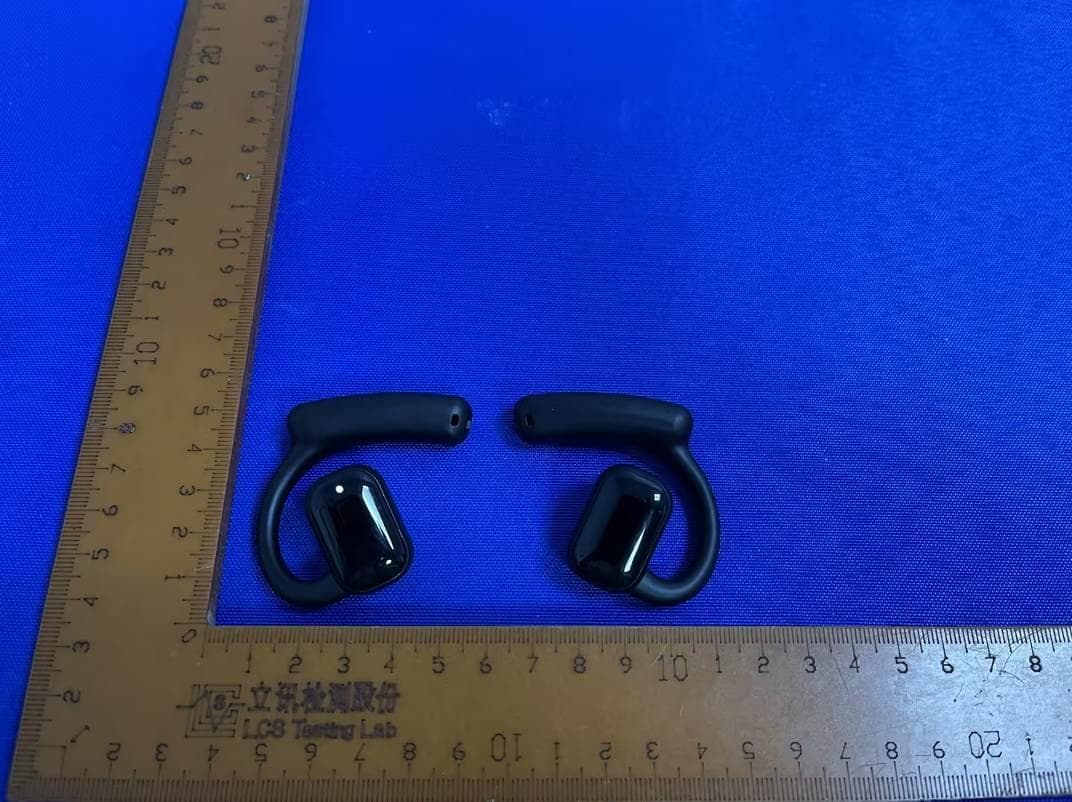
2AYLE-AVMAGIC-A6
May 16, 2023air conduction headphone
Equipment Class
DSS - Part 15 Spread Spectrum Transmitter
2AYLE-KS-G3B-13M-M
May 31, 2021Wireless Conferencing Speakerphone with Expansion Microphone(s)
Equipment Class
DXX - Part 15 Low Power Communication Device Transmitter
2AYLE-KS-G3B-13M-D
May 31, 20215.8G Wireless Dongle
Equipment Class
DXX - Part 15 Low Power Communication Device Transmitter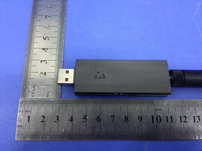
2AYLE-KSUB1GD
Jan 25, 2021Wireless Audio Dongle
Equipment Class
DTS - Digital Transmission System