2AYVYFMYKQ04A7Remote Controller
Shenzhen FIMI Robot Technology Co., Ltd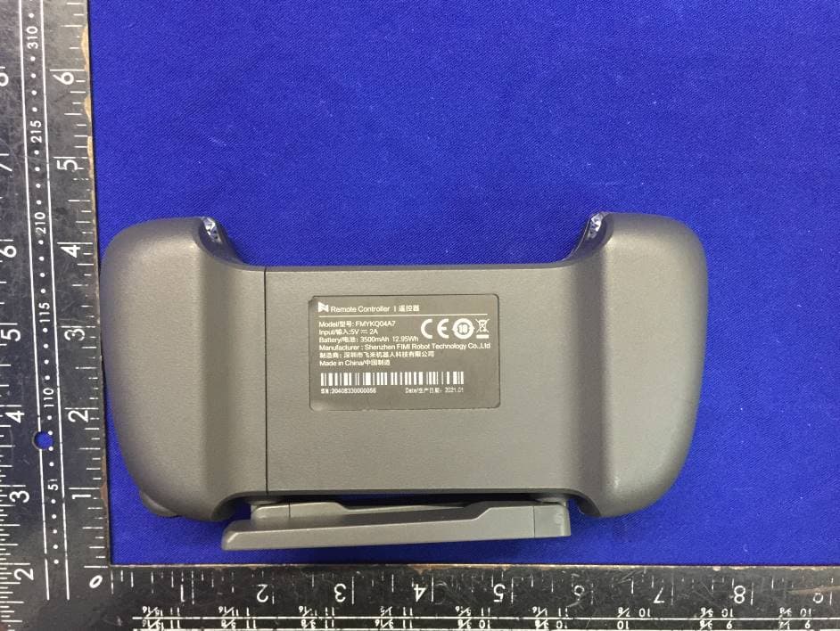
Click to zoom
Application Details
- Equipment Class
- NII - Unlicensed National Information Infrastructure TX
- Date of Grant
- Apr 29, 2021
- Application Purpose
- Original Equipment
- Date of Application
- Apr 28, 2021
- Equipment Note
- Remote Controller
- Frequency Range
- 5745.00000000 - 5825.00000000
- Country
- China
Documents & Files
Document Text
Text extracted from the exhibit documents filed with the FCC. Open a document above to read the original.
Users Manual
Please read the quick start manual carefully before using and keep it for future reference. FIMI X8 MINI Drone Quick Start Manual Product Introduction 1 Drone Clockwise propellerCounterclockwise propeller Integrated gimbal cameraLanding gearMotor RC WIFI Charging port WIFI/RC switchFlight status light TOF sensor Optical flow camera Power buttonBattery level light 2 Remote controller Stick Auto returnCharging portStick storage slot Mobile holderPower buttonBattery level lights Record button Antenna Dial Shoot button Description of RC Button Buttons Left stick Right stick Auto return Shoot button Record button Dial Power button 1 2 3 4 5 6 7 Function description Push stick upward, the drone goes up Pull stick downward, the drone goes down Toggle stick to left, the drone rotates anticlockwise Toggle stick to right, the drone rotates clockwise Push stick upward, the drone flies forward Pull stick downward, the drone flies backward Toggle stick to left, the drone flies to left Toggle stick to right, the drone flies to right Long press the button for over 2 seconds, and the drone will enter RTH mode when you hear a beep. Short press the button to cancel RTH mode Short press to shoot the picture Short press to start / stop recording Adjust the pitch angle of gimbal camera Short press to view the battery level Short press+long press 2 seconds to power on/off Up Down Counter clockwise Clockwise Note: The stick mode can be set in FIMI Navi Mini app. (The default is Mode 2) Up Down Drone heading Left stickRight stick Backward Forward Right Left Forward Backward RightLeft Drone Specifications Drone Product model:FMWRJ04A7 Max ascending speed:5m/s Max descending speed:3.5m/s Max flight speed:16m/s Operating temperature:0~40°C Suitable altitude:≤4000m FCC ID: 2AYVYFMWRJ04A7 Operating frequency:5.725-5.850GHz Dimensions:145×85×56mm (folded) 200×145×56mm (unfolded) Take-off weight:Drone with standard version battery weight: around 258g Drone with pro version battery weight: around 245g Flight time: Standard version battery usage time: 30-minutes (no wind environment and at a constant flying speed of 6m/s) Pro version battery usage time: 31-minutes (no wind environment and at a constant flying speed of 6m/s) Satellite positioning systems:GPS/GLONASS/BEIDOU Hovering accuracy:Vertical±0.1m (within TOF sensor working range) ±0.5m(when GPS positioning is active) Horizontal: ±1.5 Remote controller Product model: FMYKQ04A7 Net weight:About 260g Dimensions: 165x89x47mm Operating frequency:5.725-5.850GHz Type:Rechargeable lithium battery Battery voltage: 3500mAh Nominal voltage: 3.7V Input: 5V 2A Max transmission distance: About 8000m Operating temperature: 0~40°C Suitable altitude:≤4000m FCC ID: 2AYVYFMYKQ04A7 Note: *The standard version battery usage time is 30 minutes, measured at a constant flying speed of 6m/s (no wind or breeze environment) after being fully charged *The Pro version battery usage time is 31 minutes, measured at a constant flying speed of 6m/s (no wind or breeze environment) after being fully charged *Remote control distance reaches to 8km (FCC) in open area and no interference. All t esting and data above come from FIMI laboratory. Errors may occur in actual use because of operating and environmental changes. Gimbal camera Controllable rotation range: 10° ~ -90°(Pitch) Angular vibration range:±0.005° Lens: FOV 80° Camera aperture:f2.0 Camera focal distance:3.54mm Equivalent focal distance:26mm Sensor:1/2.6" SONY CMOS Effective pixels:12M pixels ISO range:100-3200 Shutter speed:32~1/8000s Max video resolution: 3840×2160I30fpsI25fpsI24fps Max bitrate:100Mbps File system:FAT32 Image format: JPG,JPG+DNG Video format: MP4 Recommended SD card: Micro SD(U3 grade and above)8~256GB Standard version smart battery Type:Li-ion 2S Weight: 102g Capacity:2400mAh Voltage:7.2V Limited voltage:8.4V Energy:17.28Wh Suitable charging temperature: 5~40°C Pro version smart battery Type:LiPo 2S Weight: 86g Capacity:2200mAh Voltage:7.7V Limited voltage:8.8V Energy:16.94Wh Suitable charging temperature: 5~40°C Ready to fly 1 Equip and remove the gimbal protector Equip and remove the gimbal protector as shown Equip the gimbal protector as the arrow leading Remove the gimbal protector as the arrow leading Safety tips: Please take the battery out of the drone and keep it separately when not in use. 2 Battery Hard push the battery. There will be a “click” sound if the battery is installed in place. To remove the battery, you need to press the bottom battery buckle to pull out. Battery buckle 3 Propeller Please install and remove the propellers as the picture shown. The propellers need to be installed according to the marks on the arms and propellers, and distinguished the forward and reverse propellers (the attached picture shows the forward propeller.) Need to use a screwdriver for installation and make sure the screws are locked well. To keep safe, screws should be replaced together with propellers. 4 Insert Micro SD card When installing Micro SD card, please pull out the battery. Insert the SD card into the SD card slot. When removing SD card, press the SD card to pop out. SD 5 Charge Connect the remote controller to a power adapter as shown below. When the RC is in charge, the battery level lights are flashing. When the RC is fully charged, the battery level lights go out. It takes about 2.5 hours to fully charge the RC in the powered off condition. The battery status light keeps on when charging. The battery level light off when charging finished. It takes 2.5h to fully charge the batter via 5V/2A, 1.5h via 9V/2A and 1h via 9V/3A. Use USB cable to connect the device as shown. Unfold the RC to place the device. 6 Remote controller Safety tips:User should face to the tail of drone when operating it, in case of accident caused by wrong direction. Drone heading The side of gimbal camera is head of drone. Distinguish the direction of drone through status light. 7 Distinguish the direction of drone 8 urning on/off the d…
Text truncated - open the document above for the full version.
External Photos
EUT EXTERNAL PHOTOGRAPHS EUT View 1 EUT View 2 EUT View 3 EUT View 4 Wifi ant Wifi ant EUT View 5 EUT View 6 ----------------The end----------------
ID Label/Location Info
Label and label location
Internal Photos
EUT INTERNAL PHOTOGRAPHS EUT Housing and Board View 1 Solder Board-Component View 1 Solder Board-Component View 2 Solder Board-Component View 3 Solder Board-Component View 4 Solder Board-Component View 5 Solder Board-Component View 6 Solder Board-Component View 7 Solder Board-Component View 8 Solder Board-Component View 9 Solder Board-Component View 10 Battery ----------------The end----------------
RF Exposure Info
FCC SAR Test Report Report No.ES210226050W02 Page 1 of 32 Ver.1.0 FCC SAR Test Report Report No. : ES210226050W02 Applicant : Shenzhen FIMI Robot Technology Co.,Ltd Address : 2nd Floor,East Block,Tianliao Building, 1133 Xueyuan Avenue, Taoyuan Street,Nanshan District, Shenzhen City,Guangdong Province, China Product : FIMI X8 SE Remote Controller FCC ID : 2AYVYFMYKQ04A7 Trademark : N/A Model Name : FMYKQ04A7 Standards : FCC 47 CFR Part 2 (2.1093) / IEEE C95.1:1992 / IEEE 1528:2013 KDB 865664 D01 v01r04 / KDB 865664 D02 v01r02 KDB 248227 D01 v02r02/ KDB 447498 D01 v06 / KDB 616217 D04 v01r02 KDB 941225 D01 v03r01/ KDB 941225 D05 v02r05/IEC 62209-2:2010 Sample Received Date : April 22, 2021 Date of Testing : April 23, 2021 ~ April 24, 2021 CERTIFICATION:The above equipment have been tested byEMTEK (SHENZHEN) CO., LTD.Bldg 69, Majialong Industry Zone,Nanshan District, Shenzhen, Guangdong, China,and found compliance with the requirement of the above standards. The test record, data evaluation & Equipment Under Test (EUT) configurations represented herein are true and accurate accounts of the measurements of the sample’s SAR characteristics under the conditions specified in this report.It should not be reproduced except in full, without the written approval of our laboratory. The client should not use it to claim product certification, approval, or endorsement by A2LA or any government agencies. Prepared by : Lance Li/Editor Reviewer : Joe Xia/Supervisor Approve & Authorized Signer : Lisa Wang/Manager This report is for your exclusive use. Any copying or replication of this report to or for any other person or entity, or use of our name or trademark, is permitted only with our prior written permission. This report sets forth our findings solely with respect to the test samples identified herein. The results set forth in this report are not indicative or representative of the quality or characteristics of the lot from which a test sample was taken or any similar or identical product unless specifically and expressly noted. Our report includes all of the tests requested by you and the results thereof based upon the information that you provided to us. You have 60 days from date of issuance of this report to notify us of any material error or omission caused by our negligence, provided, however, that such notice shall be in writing and shall specifically address the issue you wish to raise. A failure to raise such issue within the prescribed time shall constitute your unqualified acceptance of the completeness of this report, the tests conducted and the correctness of the report contents. Unless specific mention, the uncertainty of measurement has been explicitly taken into account to declare the compliance or non-compliance to the specification. $二维码$ FCC SAR Test Report Report No.ES210226050W02 Page 2 of 32 Ver.1.0 Table of Contents Release ControlRecord ................................................................................................................................................................ 3 1. Summary of Maximum SAR Value ....................................................................................................................................... 4 2. Description of Equipment Under Test ................................................................................................................................. 5 3. SAR Measurement System ................................................................................................................................................... 6 3.1 Definition of SpecificAbsorptionRate (SAR) ................................................................................................................. 6 3.2 SPEAG DASY System ................................................................................................................................................. 6 3.2.1 Robot.................................................................................................................................................................. 7 3.2.2 Probes ................................................................................................................................................................ 8 3.2.3 Data Acquisition Electronics (DAE) .................................................................................................................... 8 3.2.4 Phantoms ........................................................................................................................................................... 9 3.2.5 Device Holder ................................................................................................................................................... 10 3.2.6 System Validation Dipoles ................................................................................................................................ 10 3.2.7 Tissue Simulating Liquids ................................................................................................................................. 11 3.3 SAR System Verification ............................................................................................................................................ 14 3.4 SAR Measurement Procedure ................................................................................................................................... 15 3.4.1 Area & Zoom Scan Procedure ......................................................................................................................... 15 3.4.2 VolumeScan Procedure.................................................................................................................................... 15 3.4.3 Power Drift Monitoring ...................................................................................................................................... 16 3.4.4 Spatial Peak SAR Evaluation ............................................…
Text truncated - open the document above for the full version.
RF Exposure Info
Test Laboratory: Shenzhen EMTEK Co.,Ltd.Date: 2021/4/23 System Check_H5800 DUT: Dipole 5GHzV2;Type:D5GHzV2; SN:1040 Communication System: CW; Frequency: 5800 MHz;Duty Cycle: 1:1 Medium: H5G Medium parameters used: f = 5800 MHz; σ = 5.415 S/m; ε r = 35.658; ρ = 1000 kg/m 3 DASY5 Configuration: - Probe: EX3DV4 - SN3970; ConvF(5.2, 5.2, 5.2); Calibrated: 2021/3/30; - Sensor-Surface: 1.4mm (Mechanical Surface Detection) - Electronics: DAE4 Sn1418; Calibrated: 2021/3/11 - Phantom: ELI v5.0; Type: QDOVA002AA; Serial: TP:1231 - Measurement SW: DASY52, Version 52.8 (7); SEMCAD X Version 14.6.10 (7164) Pin=100mW/Area Scan (91x91x1): Interpolated grid: dx=1.000 mm, dy=1.000 mm Maximum value of SAR (interpolated) = 20.6 W/kg Pin=100mW/Zoom Scan (7x7x12)/Cube 0: Measurement grid: dx=4mm, dy=4mm, dz=2mm Reference Value = 50.784 V/m; Power Drift = 0.05 dB Peak SAR (extrapolated) = 35.0 W/kg SAR(1 g) = 8.07 W/kg; SAR(10 g) = 2.29 W/kg Maximum value of SAR (measured) = 21.5 W/kg
RF Exposure Info
Test Laboratory: Shenzhen EMTEK Co.,Ltd.Date: 2021/4/23 802.11_ch157_Ant A DUT: FMYKQ04A7 Communication System: 802.11a; Frequency: 5785 MHz;Duty Cycle: 1:1 Medium: H5G Medium parameters used: f = 5785 MHz; σ = 5.396 S/m; ε r = 35.742; ρ = 1000 kg/m 3 DASY5 Configuration: - Probe: EX3DV4 - SN3970; ConvF(5.2, 5.2, 5.2); Calibrated: 2021/3/30; - Sensor-Surface: 4mm (Mechanical Surface Detection) - Electronics: DAE4 Sn1418; Calibrated: 2021/3/11 - Phantom: ELI v5.0; Type: QDOVA002AA; Serial: TP:1231 - Measurement SW: DASY52, Version 52.8 (7); SEMCAD X Version 14.6.10 (7164) Vertical antenna A/Area Scan (121x81x1): Interpolated grid: dx=1.000 mm, dy=1.000 mm Maximum value of SAR (interpolated) = 1.20 W/kg Vertical antenna A/Zoom Scan (7x7x12)/Cube 0: Measurement grid: dx=4mm, dy=4mm, dz=2mm Reference Value = 3.452 V/m; Power Drift = -0.11 dB Peak SAR (extrapolated) = 2.64 W/kg SAR(1 g) = 0.672 W/kg; SAR(10 g) = 0.287 W/kg Maximum value of SAR (measured) = 1.14 W/kg
RF Exposure Info
Calibration Laboratory of Schmid & Partner Engineering AG Zeughausstrasse 43, 8004 Zurich, Switzerland Accredited by the Swiss Accreditation Service (SAS) The Swiss Accreditation Service is one of the signatories to the EA Multilateral Agreement for the recognition of calibration certificates Schweizerischer Kalibrierdienst Service suisse d'etalonnage C Servizio svizzero di taratura S Swiss Calibration Service Accreditation No.: SCS 0108 Client Certificate No: 05GHzV2-1040_Jun18 CALIBRATION CERTIFICATE Object D5GHzV2 - SN:1040 Calibration procedure(s) QA CAL-22.v3 Calibration procedure for dipole validation kits between 3-6 GHz I Calibration date: June 28, 2020 This calibration certificate documents the traceability to national standards, which realize the physical units of measurements (SI). The measurements and the uncertainties with confidence probability are given on the following pages and are part of the certificate. All calibrations have been conducted in the closed laboratory facility: environment temperature (22 ± 3) ° C and humidity< 70%. Calibration Equipment used (M& TE critical for calibration) Primary Standards ID# Cal Date (Certificate No.) Scheduled Calibration Power meter NAP SN: 104778 04-Apr-18 (No. 217 -02672/02673) Apr-19 Power sensor NRP-Z91 SN: 103244 04-Apr-18 (No. 217 -02672) Apr-19 Power sensor NRP-Z91 SN: 103245 04-Apr-18 (No. 217 -02673) Apr-19 Reference 20 dB Attenuator SN: 5058 (20k) 04-Apr-18 (No. 217-02682) Apr-19 Type-N mismatch combination SN: 5047.2 I 06327 04-Apr-18 (No. 217-02683) Apr-19 Reference Probe EX3DV4 SN: 3503 30-Dec-17 (No. EX3-3503_Dec17) Dec-18 DAE4 SN: 601 26-0ct-17 (No. DAE4·601_0ct17) Oct-18 Secondary Standards ID# Check Date (in house) Scheduled Check Power meter EPM-442A SN: GB37480704 07-0ct-15 (in house check Oct-16) In house check: Oct-18 Power sensor HP 8481 A SN: US37292783 07-0ct-15 (in house check Oct-16) In house check: Oct-18 Power sensor HP 8481A SN: MY41092317 07-0ct-15 (in house check Oct-16) In house check: Oct-18 RF generator R&S SMT-06 SN: 100972 15-Jun-15 (in house check Oct-16) In house check: Oct-18 Network Analyzer HP 8753E SN: US37390585 18-0ct-01 (in house check Oct-17) In house check: Oct-18 Name Function Signature T� Calibrated by: Jeton Kastrati Laboratory Technician Approved by: Katja Pokovic Technical Manager �� Issued: June 28, 2018 This calibration certificate shall not be reproduced except in full without written approval of the laboratory. Certificate No: D5GHzV2-1040_Jun18 Page 1 of 16 I --- ·- Emtek(Shenzhen)
RF Exposure Info
<Photographs of EUT> <Antenna Location> EUT Top Side EUT Bottom Side EUT Right Side EUT Left Side <EUT Front View> WWAN Antenna-B WWAN Antenna-A <Photographs of SAR Setup> Rear Face of EUT with 0 cm Gap Rear Face of EUT with 0 cm Gap Left Side of EUT with 0 cm Gap Right Side of EUT with 0 cm Gap Top Side of EUT with 0cm Gap
Test Report
Report No. ES210226050W01 Page 1 of 52 Ver.1.0 TEST REPORT Product Name : Remote Controller Model Number : FMYKQ04A7 FCC ID : 2AYVYFMYKQ04A7 Prepared for : Shenzhen FIMI Robot Technology Co.,Ltd Address : 2nd Floor,East Block,Tianliao Building, 1133 Xueyuan Avenue, Taoyuan Street,Nanshan District, Shenzhen City,Guangdong Province, China Prepared by : EMTEK (SHENZHEN) CO., LTD. Address : Building 69, Majialong Industry Zone, Nanshan District, Shenzhen, Guangdong, China Tel: (0755) 26954280 Fax: (0755) 26954282 Report Number : ES210226050W01 Date(s) of Tests : Mar. 5, 2021 to Mar. 25, 2021 Date of issue : Mar. 30, 2021 $二维码$ Report No. ES210226050W01 Page 2 of 52 Ver.1.0 1 TEST RESULT CERTIFICATION Applicant : Shenzhen FIMI Robot Technology Co.,Ltd Address : 2nd Floor,East Block,Tianliao Building, 1133 Xueyuan Avenue, Taoyuan Street, Nanshan District, Shenzhen City,Guangdong Province, China Manufacturer : Shenzhen FIMI Robot Technology Co.,Ltd Address : 2nd Floor,East Block,Tianliao Building, 1133 Xueyuan Avenue, Taoyuan Street, Nanshan District, Shenzhen City,Guangdong Province, China EUT : Remote Controller Model Name : FMYKQ04A7 Trademark : N/A Measurement Procedure Used: APPLICABLE STANDARDS STANDARD TEST RESULT FCC 47 CFR Part 2, Subpart J FCC 47 CFR Part 15, Subpart E PASS The above equipment was tested by EMTEK (SHENZHEN) CO., LTD. The test data, data evaluation, test procedures, and equipment configurations shown in this report were made in accordance with the procedures given in ANSI C63.10 (2013) and the energy emitted by the sample EUT tested as described in this report is in compliance with the requirements of FCC Rules Part 2 and Part 15.407 The test results of this report relate only to the tested sample identified in this report. Date of Test : Mar. 5, 2021 to Mar. 25, 2021 Prepared by : Sewen Guo /Editor Reviewer : Joe Xia/Supervisor Approved & Authorized Signer : Lisa Wang/Manager Report No. ES210226050W01 Page 3 of 52 Ver.1.0 TABLE OF CONTENTS 1 TEST RESULT CERTIFICAT I O N ....................................................................................................... 2 2 EUT TECHNICAL DESCRIPTION ..................................................................................................... 4 3 SUMMARY OF TEST RESULT .......................................................................................................... 5 4 TEST METHODOLOGY ..................................................................................................................... 6 4.1 GENERAL DESCRIPTION OF APPLIED STANDARDS ............................................................. 6 4.2 MEASUREMENT EQUIPMENT USED ....................................................................................... 6 4.3 DESCRIPTION OF TEST MODES .............................................................................................. 7 5 FACILITIES AND ACCREDITATIONS ............................................................................................... 8 5.1 FACILITIES ................................................................................................................................. 8 5.2 LABORATORY ACCREDITATIONS AND LISTINGS .................................................................. 8 6 TEST SYSTEM UNCERTAINTY ........................................................................................................ 9 7 SETUP OF EQUIPMENT UNDER TEST ......................................................................................... 10 7.1 RADIO FREQUENCY TEST SETUP ......................................................................................... 10 7.2 RADIO FREQUENCY TEST SETUP ......................................................................................... 10 7.3 CONDUCTED EMISSION TEST SETUP .................................................................................. 12 7.4 BLOCK DIAGRAM CONFIGURATION OF TEST SYSTEM ...................................................... 13 7.5 SUPPORT EQUIPMENT ........................................................................................................... 13 8 TEST REQUIREMENTS................................................................................................................... 14 8.1 BANDWIDTH MEASUREMENT ............................................................................................... 14 8.2 MAXIMUM CONDUCTED OUTPUT POWER ........................................................................... 23 8.3 MAXIMUM PEAK POWER DENSITY ....................................................................................... 25 8.4 FREQUENCY STABILITY ......................................................................................................... 32 8.5 UNDESIRABLE RADIATED SPURIOUS EMISSION ................................................................ 34 8.6 POWER LINE CONDUCTED EMISSIONS ............................................................................... 48 8.7 ANTENNA APPLICATION ......................................................................................................... 51 Report No. ES210226050W01 Page 4 of 52 Ver.1.0 2 EUT TECHNICAL DESCRIPTION Characteristics Description Product Remote Controller Model Number FMYKQ04A7 Wifi Type UNII-3 with 5725MHz-5850MHz Band WLAN Supported 802.11a 802.11n(20MHz channel bandwidth) 802.11n(40MHz channel bandwidth) 802.11ac(20MHz channel bandwidth) 802.11ac(40MHz channel bandwidth) 802.11ac(80MHz channel bandwidth) Data Rate 802.11a:54/48/36/24/18/12/9/6Mbps Modulation OFDM with BPSK/QPSK/16QAM/64QAM for 802.11a; OFDM with BPSK/QPSK/16QAM/64QAM/256QAM for 802.11ac; Frequency Range UNII-3 with 5725MHz-5850MHz Band 5745-5825MHz for 802.11a; 5745-5825MHz for 802.11n(HT20); 5745-5825MHz for 802.11ac(HT20); 5755-5795MHz for 802.11n(HT40); 5755-5795MHz for 802.11ac(HT40); 5775MHz for 802.11ac(HT80); TPC Function Applicable Not Applicable Antenna Type External Antenna Antenna Gain 5.4 dB…
Text truncated - open the document above for the full version.
Test Setup Photos
TEST SETUP PHOTOGRAPHS 1.1. Photos of Conducted Emission Measurement 1.2. Photos of Radiation Emission Measurement Spurious Emission Test Setup (Below 1GHz) Spurious Emission Test Setup (Above 1GHz) ----------------The end----------------
Contact Information
Applicant
pan beng
Test Firm
EMTEK (Shenzhen) Co., Ltd.Lisa Wang
[email protected]86 755 26954280
Technical Specifications
| # | Rule Parts | Frequency Range | Power Output |
|---|---|---|---|
| 1 | 15E | 5.75 GHz - 5.83 GHz | 293.00 mW |
Other Applications from Shenzhen FIMI Robot Technology Co., Ltd
2AYVYFMWRJ03A9
Jan 17, 2024FIMI X8 Pro Drone
Equipment Class
DTS - Digital Transmission System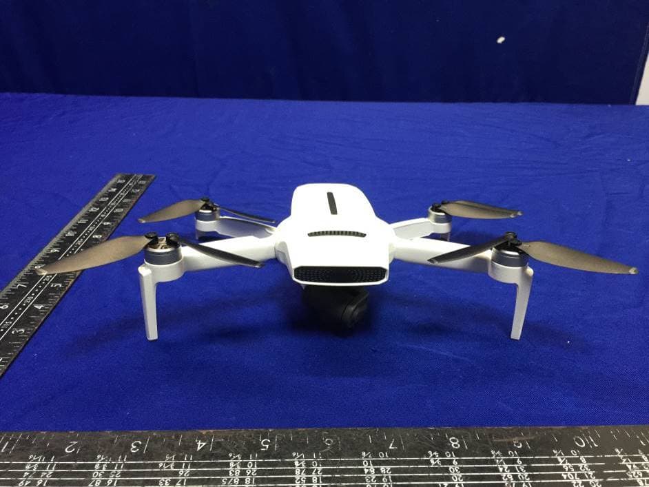
2AYVYFMWRJ04A7
Apr 28, 2021FIMI X8 Mini Drone
Equipment Class
NII - Unlicensed National Information Infrastructure TX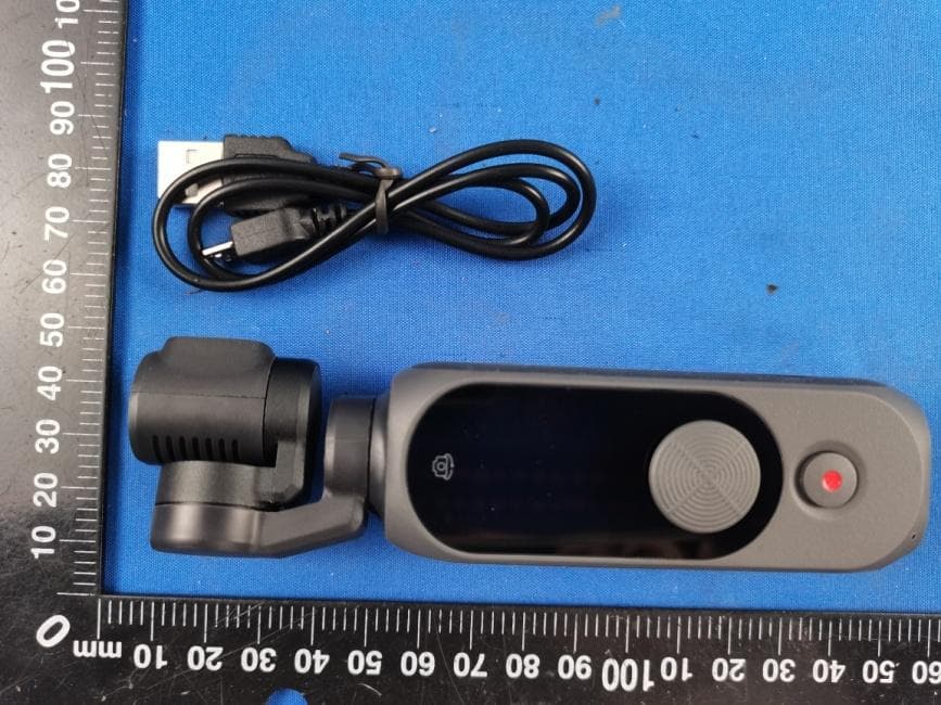
2AYVYYTXJ06FM
Feb 25, 2021PALM 2 Gimbal Camera
Equipment Class
DTS - Digital Transmission System