2AZWZ-D8DASH CAMERA
KAWA ELECTRONICS COMPANY LIMITED
Click to zoom
Application Details
- Equipment Class
- DTS - Digital Transmission System
- Date of Grant
- Jul 29, 2023
- Application Purpose
- Original Equipment
- Date of Application
- Jul 29, 2023
- Equipment Note
- DASH CAMERA
- Frequency Range
- 2412.00000000 - 2462.00000000
- Country
- China
Documents & Files
Document Text
Text extracted from the exhibit documents filed with the FCC. Open a document above to read the original.
Users Manual
Warranty: 12-month limited warranty Manufacturer: KAWA ELECTRONICS COMPANY LIMITED Address: FLAT A 21/F CHEUNG LEE IND BLDG 9 CHEUNG LEE ST CHAI WAN HONG KONG E-mail: [email protected] Website: www.kawa-in.com Product Appearance Brand Name:KAWAModel: D8 Power supply: car chargerImage resolution: 3840x2160 Cooling hole 1 Base installation slot 2 Rear camera interface 3 Display 4 LED 5 Power button 6 Reset button 7 Micro SD card slot 8 Power interface 9 MIC 10 Function button 11 Speaker 12 Lens 13 123 4 8 9 1213 10 11 6 7 5 Basic Parameters Product Name: DASH CAMERA Input: 5V 2A Product Installation Button Functions LED Functions Quick configuration Note: the product, accessories, interface shown in the user manual are for your reference only. Due to the upgrade of product, your device may be slightly different with the schematic diagrams. Pls refer to the actual device. 1.Download the app. Download KAWA AUTO APP by scanning the QR code below.(After downloading the app, you can use it to watch the real-time video recorded by the dash cam, adjust the dash cam's installation angle, and view/download the recorded videos.) 2.Add to APP. Open the KAWA AUTO APP, click on the "+" in the upper right corner, select “KAWA Dash Cam D8” , and follow the instructions in the APP to operate. *During the process of adding the dash cam to the app, the phone needs to connect to the dash cam's hotspot. 1.Please connect your phone to the dash cam's hotspot (make sure the dash cam's hotspot is turned on), not to another phone's hotspot or your home WiFi. 1.Hotspot Name: KAWA_D8_XXXX (or as indicated on the product label) Initial Password: 12345678 1.To connect the hotspot of the dash cam, the operating system of your phone should be Android5.0 or iOS8.0 and above. Q&A 1.Why are the videos missing in the album? -The video may have been overwritten by a new one. -All videos and photos recorded by the device are stored using a loop overwrite method. Once the storage limit is reached, the dash cam will automatically delete the earliest recorded videos. -To ensure important videos are not erased, please backup them to other devices such as your phone or computer in a timely manner. 3.Does viewing videos and photos in the album on the dash cam consume mobile data? -No, it won't. -The dash cam itself acts as a LAN Wi-Fi, and when connected to a phone, it uses the dash cam's network, so it won't consume mobile data. Note: The dash cam's Wi-Fi network doesn't support internet access. If you want to access the internet, please disconnect from the dash cam. 2.Why are emergency videos quickly overwritten in a loop? -If your driving style is aggressive, frequently accelerating or decelerating sharply, or driving on poorly maintained roads, and you have set a high collision sensitivity, it is easy to generate emergency videos. Once the emergency video storage limit is reached, newly generated emergency videos will overwrite previous ones. If you fit the above criteria, it is recommended to choose a low sensitivity setting. If the dash cam is turned on, the LED status will indicate the corresponding function. You can press/click the power button for following times or durations to achieve different functions. StateOperationFunction Power-off (the power supply is connected) Press and hold the power button for 3sTo turn on the Power-on Press and hold the power button for 3sTo turn off the Button name Power Button Click the power buttonP ress to turn screen on/off dash cam dash cam Instructions for Use of Micro SD Card 1.The Micro SD card is not included in the package. You need to buy your own Micro SD card. 2.The dash cam supports standard Micro SD card. Please use a 64GB-256GB Micro SD card with data rate of Class 10 or above. 3.Please insert an appropriate Micro SD card before using the dash cam. 4.The default file partition format of the Micro SD card may be different from the format of the dash cam. When the Micro SD card is inserted for the first time, please format it in the dash cam before use.This will delete all files from the Micro SD card. Please back up the important data to another device in advance. 5.To prevent the decline of reading/writing speed after long-term use, it is recommended to format the Micro SD card in the dash cam once a month. 6.After repeated overwriting, the Micro SD card may be damaged or write at a lower speed, which will affect its ability to save video and image files. If this happens, please replace the Micro SD card immediately. The manufacturer shall not be held liable for any malfunction caused by the Micro SD card. 7.Please use a reputable and high-quality Micro SD card. For an inferior Micro SD card, there may be a difference between the actual reading/writing speed and nominal speed, and between the actual storage capacity and nominal capacity. The manufacturer shall not be held liable for any video loss or damage caused by a low-quality Micro SD card. 8.In order not to damage the recorded video or Micro SD card, please do not insert or remove the Micro SD card after the dash cam is turned on. Precautions before Installation 1.To ensure correct installation, please use the supplied accessories in the specified manner. If you use non-supplied or incompatible accessories, they may damage the internal parts of this product, or they may become loose and cause this product to fall off. 2.DO NOT install this product at a hot or humid location, such as: -Near the heater, air vents or air-conditioning vents; or -Locations that may be exposed to rain, for example, near the vehicle door. DO NOT install this product at locations that block the driver's view, compromises the performance of any operating system or safety function of the vehicle, including airbags and hazard light switch, or compromises the driver's ability to operate the vehicle safely. 4.DO NOT install this product in front of or at sides of the dashboard, vehicle door or pillar where one of the airbags may unfold. Please ref…
Text truncated - open the document above for the full version.
Attestation Statements
[KAWA ELECTRONICS COMPANY LIMITED] [FLAT A 21/F CHEUNG LEE IND BLDG 9 CHEUNG LEE ST CHAI WAN] [HONG KONG] [CHINA] Date: May. 30, 2023 Federal Communications Commission Authorization and Evaluation Division 7435 Oakland Mills Road Columbia, MD 21046 FCC ID: 2AZWZ-D8 US Agent – Attestation Statement / Part 2.911(d)(7) [KAWA ELECTRONICS COMPANY LIMITED] certifies, that as of [May. 30, 2023], we have designated FCC US Agent, LLC to accept service of process on our behalf for FCC ID: 2AZWZ- D8. [KAWA ELECTRONICS COMPANY LIMITED], accepts to maintain an agent of service of process in the United States for no less than one year after either the grantee has permanently terminated all marketing and importation of the applicable equipment within the U.S., or the conclusion of any Commission-related administrative or judicial proceeding involving the equipment, whichever is later. FCC US Agent, LLC, accepts as of the date of the filing of this application, the obligation of being the designated agent for the purpose of accepting service of process on behalf of [KAWA ELECTRONICS COMPANY LIMITED] for FCC ID: 2AZWZ-D8. Designated Agent Information: Company Name: FCC US Agent, LLC FRN: 0033402884 Address: 3722 Illinois Avenue, Saint Charles, IL, 60174, USA Contact Person: Tim Payne Phone: 708-571-3148 Email: [email protected] Sincerely, Company: [KAWA ELECTRONICS COMPANY LIMITED] Designated Agent: FCC US Agent, LLC Company Representative: [Yuwei Zhang] Tel: 13428982606 Email: [email protected] Designated Agent Representative: Tim Payne Signature: Signature:
Cover Letter(s)
KAWA ELECTRONICS COMPANY LIMITED FLAT A 21/F CHEUNG LEE IND BLDG 9 CHEUNG LEE ST CHAI WAN HONG KONG CHINA Agent Authorization Company: KAWA ELECTRONICS COMPANY LIMITED Address: FLAT A 21/F CHEUNG LEE IND BLDG 9 CHEUNG LEE ST CHAI WAN HONG KONG CHINA Product Name: DASH CAMERA Model Number(s): D8, D8 Pro, D801, D802, D803 Product Description: DASH CAMERA We authorize MiCOM Labs Inc., 575 Boulder Court, Pleasanton, California 94566, USA, to act on our behalf on all matters concerning the certification of above named equipment. We declare that MiCOM Labs Inc. is allowed to forward all information related to the approval and certification of equipment to the regulatory agencies as required and to discuss any issues concerning the approval application. Any and all acts carried out by MiCOM Labs on our behalf shall have the same effect as acts of our own. Signature: Date: Jul. 24, 2023 Name: Yuwei Zhang Title: General Manager Company: KAWA ELECTRONICS COMPANY LIMITED
Cover Letter(s)
KAWA ELECTRONICS COMPANY LIMITED FLAT A 21/F CHEUNG LEE IND BLDG 9 CHEUNG LEE ST CHAI WAN HONG KONG CHINA Jul. 24, 2023 Office of Engineering Technology Federal Communications Commission 7435 Oakland Mills Road Columbia, MD 21046 USA Subject: Explanation of differences between product types FCC ID: 2AZWZ-D8 Models: D8, D8 Pro, D801, D802, D803 To Whom It May Concern: We, The KAWA ELECTRONICS COMPANY LIMITED hereby declare that the model : D8 is identical with the model : D8 Pro, D801, D802, D803 except for the model name and plastic appearance color. Except for the different above, no other modification is performed. Sincerely, KAWA ELECTRONICS COMPANY LIMITED Signature: [Yuwei Zhang, General Manager]
External Photos
Report No.: AGC01519230504AP02 Page 1 of 7 EXTERNAL PHOTOS The prototype model is D8 All VIEW OF EUT TOP VIEW OF EUT Report No.: AGC01519230504AP02 Page 2 of 7 BOTTOM VIEW OF EUT FRONT VIEW OF EUT Report No.: AGC01519230504AP02 Page 3 of 7 BACK VIEW OF EUT LEFT VIEW OF EUT Report No.: AGC01519230504AP02 Page 4 of 7 RIGHT VIEW OF EUT The prototype model is D8 Pro All VIEW OF EUT Report No.: AGC01519230504AP02 Page 5 of 7 TOP VIEW OF EUT BOTTOM VIEW OF EUT Report No.: AGC01519230504AP02 Page 6 of 7 FRONT VIEW OF EUT BACK VIEW OF EUT Report No.: AGC01519230504AP02 Page 7 of 7 LEFT VIEW OF EUT RIGHT VIEW OF EUT ****************************************End of Report*************************************
ID Label/Location Info
FCC ID Label Location 10mm*10mm FCC ID: 2AZWZ-D8
Internal Photos
Report No.: AGC01519230504AP02 Page 1 of 15 INTERNAL PHOTOS The prototype model is D8 PORT VIEW OF EUT (FIGURE 1) PORT VIEW OF EUT (FIGURE 2) Report No.: AGC01519230504AP02 Page 2 of 15 OPEN VIEW OF EUT BATTERY VIEW OF EUT Report No.: AGC01519230504AP02 Page 3 of 15 ANTENNA CLOSE-UP PHOTO INTERNAL VIEW OF EUT (FIGURE 1) WIFI Antenna Report No.: AGC01519230504AP02 Page 4 of 15 INTERNAL VIEW OF EUT (FIGURE 2) INTERNAL VIEW OF EUT (FIGURE 3) Report No.: AGC01519230504AP02 Page 5 of 15 INTERNAL VIEW OF EUT (FIGURE 4) INTERNAL VIEW OF EUT (FIGURE 5) Report No.: AGC01519230504AP02 Page 6 of 15 INTERNAL VIEW OF EUT (FIGURE 6) INTERNAL VIEW OF EUT (FIGURE 7) Report No.: AGC01519230504AP02 Page 7 of 15 INTERNAL VIEW OF EUT (FIGURE 8) INTERNAL VIEW OF EUT (FIGURE 9) Report No.: AGC01519230504AP02 Page 8 of 15 INTERNAL VIEW OF EUT (FIGURE 10) The prototype model is D8 Pro PORT VIEW OF EUT (FIGURE 1) Report No.: AGC01519230504AP02 Page 9 of 15 PORT VIEW OF EUT (FIGURE 2) OPEN VIEW OF EUT Report No.: AGC01519230504AP02 Page 10 of 15 BATTERY VIEW OF EUT ANTENNA CLOSE-UP PHOTO WIFI Antenna Report No.: AGC01519230504AP02 Page 11 of 15 INTERNAL VIEW OF EUT (FIGURE 1) INTERNAL VIEW OF EUT (FIGURE 2) Report No.: AGC01519230504AP02 Page 12 of 15 INTERNAL VIEW OF EUT (FIGURE 3) INTERNAL VIEW OF EUT (FIGURE 4) Report No.: AGC01519230504AP02 Page 13 of 15 INTERNAL VIEW OF EUT (FIGURE 5) INTERNAL VIEW OF EUT (FIGURE 6) Report No.: AGC01519230504AP02 Page 14 of 15 INTERNAL VIEW OF EUT (FIGURE 7) INTERNAL VIEW OF EUT (FIGURE 8) Report No.: AGC01519230504AP02 Page 15 of 15 INTERNAL VIEW OF EUT (FIGURE 9) INTERNAL VIEW OF EUT (FIGURE 10) ****************************************End of Report*************************************
RF Exposure Info
RF EXPOSURE EVALUATION 1. PRODUCT INFORMATION FCC ID 2AZWZ-D8 Product Description DASH CAMERA Model Name D8, D8 Pro, D801, D802, D803 Frequency Band (Operating) WLAN: 2.412GHz ~ 2.462GHz WLAN: 5.18GHz ~ 5.32GHz / 5.50GHz ~ 5.70GHz WLAN: 5.745GHz ~ 5825GHz Bluetooth: 2.402GHz ~ 2.480GHz Others (NFC:13.56MHz) Device Category Portable (<20cm separation) Mobile (>20cm separation) Others: Antenna Diversity Single antenna Multiple antennas Max. Output Power (Average) IEEE 802.11b:12.28dBm; IEEE 802.11g:11.21dBm; IEEE 802.11n(20):11.60dBm; IEEE 802.11n(40):11.32dBm Max. Output Power (Peak) IEEE 802.11b:15.27dBm; IEEE 802.11g:18.88dBm; IEEE 802.11n(20):19.30dBm; IEEE 802.11n(40):19.10dBm Antenna Gain 2.8dBi Minimum Assessment Distance 20cm Evaluation Applied MPE Evaluation SAR Evaluation Evaluation Result Pass 2. PORTABLE DEVICE EVALUATION METHOD AND LIMIT Following FCC KDB 447498 D01 “General SAR test exclusion guidance” The corresponding SAR Exclusion Threshold condition, listed below: 1) The 1-g and 10-g SAR test exclusion thresholds for 100 MHz to 6 GHz at test separation distances ≤50 mm are determined by: [(max. power of channel, including tune-up tolerance, mW)/(min. test separation distance, mm)] [if(GHz)] s 3.0 for 1-g SAR and ñ 7.5 for 10-g extremity SAR, where f(GHz) is the RF channel transmit frequency in GHz. Power and distance are rounded to the nearest mW and mm before calculation. The result is rounded to one decimal place for comparison The test exclusions are applicable only when the minimum test separation distance is ≤50 mm and for transmission frequencies between 100 MHz and 6 GHz. When the minimum test separation distance is < 5 mm, a distance of 5 mm is applied to determine SAR test exclusion. 2) At 100 MHz to 6 GHz and for test separation distances > 50 mm, the SAR test exclusion threshold is determined according to the following: a) [Threshold at 50 mm in step 1) + (test separation distance - 50mm) ( f(MHz)/150)] mW, at 100MHz to 1500 MHz; b) [Threshold at 50 mm in step 1) + (test separation distance - 50 mm)-10] mW at > 1500 MHz and ≤6 GHz; 3) At frequencies below 100 MHz, the following may be considered for SAR test exclusion. a) The threshold at the corresponding test separation distance at 100 MHz in step 2) is multiplied by [1 + log(100/f(MHz))] for test separation distances > 50 mm and < 200 mm. b) The threshold determined by the equation in a) for 50 mm and 100 MHz is multiplied by 1/2 for test separation distances ñ 50 mm. c) SAR measurement procedures are not established below 100 MHz. When SAR test exclusion cannot be applied, a KDB inquiry is required to determine SAR evaluation requirements for any test results to be acceptable. 3. MOBILE DEVICE EVALUATION METHOD AND LIMIT Human exposure to RF emissions from mobile devices (47 CFR §2.1091) may be evaluated based on the MPE limits adopted by the FCC for electric and magnetic field strength and/or power density, as appropriate, since exposures are assumed to occur at distances of 20 cm or more from persons. LIMITS FOR GENERAL POPULATION / UNCONTROLLED EXPOSURE Frequency Range (MHz) E-field Strength (E) (V/m) Magnetic Field Strength (H) (A/m) Power Density (S) (mW/cm 2 ) Averaging Time |E| 2 , |H| 2 or S (Minutes) 0.3 -- 1.34 614 1.63 (100)* 30 1.34 -- 30 824/f 2.19/f (180/f 2 )* 30 30 -- 300 27.5 0.073 0.2 30 300 -- 1500 -- -- f/1500 30 1500 -- 100,000 -- -- 1.0 30 *Note: 1. f= Frequency in MHz * Plane-wave Equivalent Power Density 2. The averaging time for General Population/Uncontrolled exposure to fixed transmitters is not applicable for mobile and portable transmitters. See 47 CFR §§2.1091 and 2.1093 on source-based time-averaging requirement for mobile and portable transmitters. S=PG/4πR² Where: S=power density P=power input to antenna G=power gain of the antenna in the direction of interest relative to an isotropic radiator R=distance to the center of radiation of the antenna 4. MEASUREMENT RESULT A minimum test separation distance ≥ 20 cm is required between the antenna and radiating structures of the device and nearby persons to apply mobile device exposure limits. The distance must be at least 20 cm and fully supported by the operating and installation configurations of the transmitter and its antenna(s), according to the source-based time-averaged maximum power requirements of § 2.1091(d)(2). In cases where cable losses or other attenuations are applied to determine compliance, the most conservative operating configurations and exposure conditions must be evaluated. 2.4G WLAN: Antenna Gain=2dBi (Numeric 1.58), π=3.14 Note: 1. Only the worst case recorded. 5. CONCLUSION Since Source-base time average power is below SAR test exclusion power thresholds, the SAR evaluation is not required. Test Mode Test Frequency (MHz) Max.Output Power (dBm) Max.Output Power (mW) Power Density (mW/cm 2 ) Measurement Limit (mW/cm 2 ) 2.4G WLAN_802.11b 2412 12.28 16.90 0.0053 1
Test Report
Antenna Testing Report Customer:Shenzhen Apical Technology CO.Ltd. Project Name:20702 Report version:May 11, 2023 A0 Author:Wenbo Huang 1 SUNNYWAY TECHNOLOGY(CHINA) Model Name:20702 Record VersionReport dateRemark A02023.05.11Antenna test report A1 A2 A3 A4 A5 A6 A7 A8 A9 2 /18 Contents 1.Record............................................................................................. 2.Project Overview ................................................................................. 3.Equipment List.................................................................................... 4.Project pictures and Passive fixturs............................................................ 5.Matching Circuit .............................................................................. 6.Passive efficiency and gain ..................................................................... 7.Radiation Pattern................................................................................. 8.OTA test data ................................................................................. 9.Environment Specification..................................................................... 3 /18 Prototype statusDebugging machine Device type Number of antennasWIFI antenna 、 GPS antenna Frequency band 2G: N/A 3G: N/A 4G-LTE: N/A 5G-NR: N/A GPS + WIFI 802.11 a/b/g/n Structural styleFPC+Cable Environment adjustment No change Matching modificationNo change Project Overview 4 /18 Equipment List Equipments Items Tota l Quantity Quantity for Shanghai R&D Quantity for Shenzhen R&D Quantity for ChongQing R&D OTA chamber10451 5G Tester ( SP9500-CTS ) 3111 R&S Tester ( high configuration CMW500 ) 6321 Japan Anritsu Tester ( Dual Channel 8820 ) 422-- NB- IoT Tester (SP8315)3111 Agilent Tester ( 8960 ) 944-- Agilent Network Analyzer ( E5062A ) 733 1 Agilent Network Analyzer ( E5071C 8.5GHZ ) 11551 Agilent Network Analyzer ( E5071B 8.5GHZ ) 7331 R&S Network Analyzer ( ZND ) 9441 R&S Network Analyzer ( ZVB ) 3111 OTA head hand / ear hand / arm hand 5221 GPS/WIFI active test equipment522 1 The industry's top 64 sensors OTA chamber Frequency range: 400MHz-11GHz Device Llimitation: 2M Load-bearing limitation:100KG 5 /18 Project pictures 6 /18 WIFI天线尺寸:22.2*7mm/背胶3M9495LE Matching Circuit 7 /18 WiFi: unchanged GPS: unchanged Passive standing wave 8 /18 VSWR WiFiGPS Passive Efficiency and Gain 9 /18 10 /18 Radiation Pattern 2D cross-sectional view WiFi GPS 11 /18 3D For 2450MHz Radiation Pattern 12 /18 3D For 1561MHz Radiation Pattern 3D For 1575MHz 13 /18 OTA test data WIFI: 14 /18 GPS test data Thank You Shanghai R&D Center: 1F, Building 4, No.99, Lane 215, Gaoguang Road, Qingpu District, Shanghai, 201799, PRC Shenzhen R&D Center: 6th Floor, Building 5, NantaiyunChuanggu Center, Guangming District, Shenzhen, 518107, PRC ChongQing R&D Center: 1F, ARM Ecological Industrial Park, 19 East Datugu Road, Xiantao, Yubei District, Chongqing, 401120, PRC Huizhou Factory: 4-5F, No.1, Central Village Road, Longhu Industrial Zone, Shuikou Town, Huicheng District, Huizhou, 516255, PRC TEL:021-60835368 E-mail:[email protected] www.sunnyway-iot.com 15 /18
Test Report
Page 1 of 75 Report No.: AGC01519230504FE05 FCC ID : 2AZWZ-D8 APPLICATION PURPOSE : Original Equipment PRODUCT DESIGNATION : DASH CAMERA BRAND NAME : KAWA, APICAL MODEL NAME : D8, D8 Pro, D801, D802, D803 APPLICANT : KAWA ELECTRONICS COMPANY LIMITED DATE OF ISSUE : May 29, 2023 STANDARD(S) TEST PROCEDURE(S) : FCC Part 15.247 REPORT VERSION : V1.0 Attestation of Global Compliance (Shenzhen) Co., Ltd FCC Test Report Report No.: AGC01519230504FE05 Page 2 of 75 REPORT REVISE RECORD Report Version Revise Time Issued Date Valid Version Notes V1.0 / May 29, 2023 Valid Initial Release Report No.: AGC01519230504FE05 Page 3 of 75 TABLE OF CONTENTS 1. VERIFICATION OF CONFORMITY .................................................................................................................. 5 2. GENERAL INFORMATION .............................................................................................................................. 6 2.1. PRODUCT DESCRIPTION ........................................................................................................................ 6 2.2. TABLE OF CARRIER FREQUENCYS ....................................................................................................... 6 2.3. IEEE 802.11N MODULATION SCHEME .................................................................................................... 7 2.4. RELATED SUBMITTAL(S) / GRANT (S) .................................................................................................... 7 2.5. TEST METHODOLOGY ............................................................................................................................. 7 2.6. SPECIAL ACCESSORIES ......................................................................................................................... 7 2.7. EQUIPMENT MODIFICATIONS ................................................................................................................. 7 2.8. ANTENNA REQUIREMENT....................................................................................................................... 8 3. MEASUREMENT UNCERTAINTY ................................................................................................................... 9 4. DESCRIPTION OF TEST MODES ................................................................................................................. 10 5. SYSTEM TEST CONFIGURATION ................................................................................................................ 11 5.1. CONFIGURATION OF EUT SYSTEM ...................................................................................................... 11 5.2. EQUIPMENT USED IN EUT SYSTEM ..................................................................................................... 11 5.3. SUMMARY OF TEST RESULTS .............................................................................................................. 11 6. TEST FACILITY .............................................................................................................................................. 11 7. OUTPUT POWER ........................................................................................................................................... 13 7.1. MEASUREMENT PROCEDURE ............................................................................................................. 13 7.2. TEST SET-UP (BLOCK DIAGRAM OF CONFIGURATION) .................................................................... 13 7.3. LIMITS AND MEASUREMENT RESULT .................................................................................................. 14 8. BANDWIDTH .................................................................................................................................................. 15 8.1. MEASUREMENT PROCEDURE ............................................................................................................. 15 8.2. TEST SET-UP (BLOCK DIAGRAM OF CONFIGURATION) .................................................................... 15 8.3. LIMITS AND MEASUREMENT RESULTS ............................................................................................... 16 9. CONDUCTED SPURIOUS EMISSION........................................................................................................... 29 9.1. MEASUREMENT PROCEDURE ............................................................................................................. 29 9.2. TEST SET-UP (BLOCK DIAGRAM OF CONFIGURATION) .................................................................... 29 9.3. MEASUREMENT EQUIPMENT USEDJN ................................................................................................ 29 9.4. LIMITS AND MEASUREMENT RESULT .................................................................................................. 29 Report No.: AGC01519230504FE05 Page 4 of 75 10. MAXIMUM CONDUCTED OUTPUT POWER SPECTRAL DENSITY ........................................................ 44 10.1 MEASUREMENT PROCEDURE ............................................................................................................ 44 10.2 TEST SET-UP (BLOCK DIAGRAM OF CONFIGURATION) ................................................................... 44 10.3 MEASUREMENT EQUIPMENT USED ................................................................................................... 44 10.4 LIMITS AND MEASUREMENT RESULT ................................................................................................. 44 11. RADIATED EMISSION ................................................................................................................................. 51 11.1. MEASUREMENT PROCEDURE............................................................................................................ 51 11.2. TEST SETUP ........................................................................................…
Text truncated - open the document above for the full version.
Test Setup Photos
Report No.: AGC01519230504AP01 Page 1 of 2 TEST SETUP PHOTOS RADIATED EMISSION TEST SETUP BELOW 1GHz RADIATED EMISSION TEST SETUP ABOVE 1GHz Report No.: AGC01519230504AP01 Page 2 of 2 RF CONDUCTED TEST SETUP ****************************************End of Report*************************************
Contact Information
Applicant
Yuwei Zhang
Technical Contact
Test Firm
Attestation of Global Compliance (Shenzhen) Co., LDoris Li
[email protected]+86-755-25234088
Technical Specifications
| # | Rule Parts | Frequency Range | Power Output |
|---|---|---|---|
| 1 | 15C | 2.41 GHz - 2.46 GHz | 85.10 mW |
Other Applications from KAWA ELECTRONICS COMPANY LIMITED
2AZWZ-MINI7
Mar 17, 2026DASH CAMERA
Equipment Class
DTS - Digital Transmission System2AZWZ-D9
Jan 09, 2026DASH CAMERA
Equipment Class
DTS - Digital Transmission System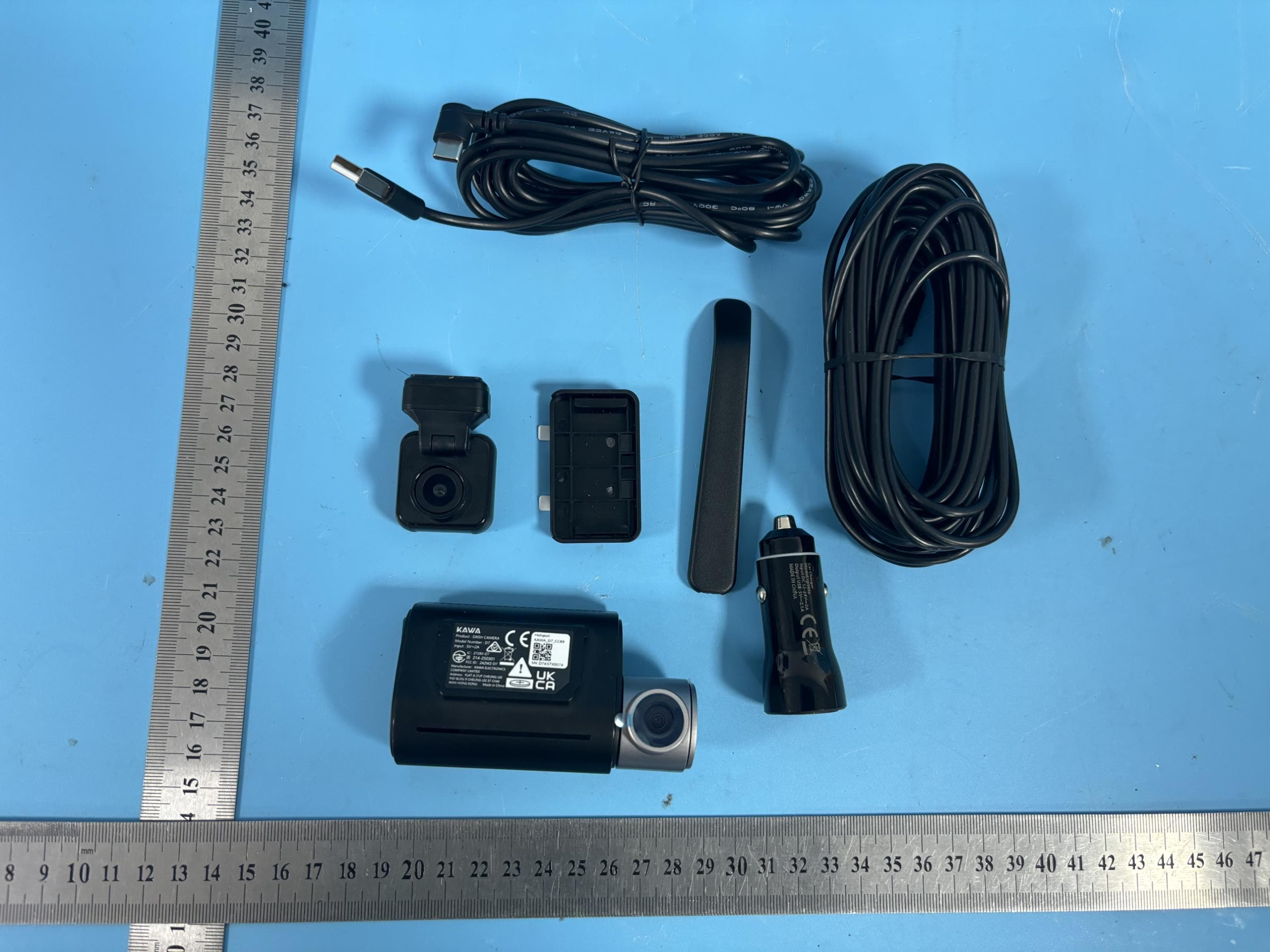
2AZWZ-D7
Sep 29, 2025DASH CAMERA
Equipment Class
DTS - Digital Transmission System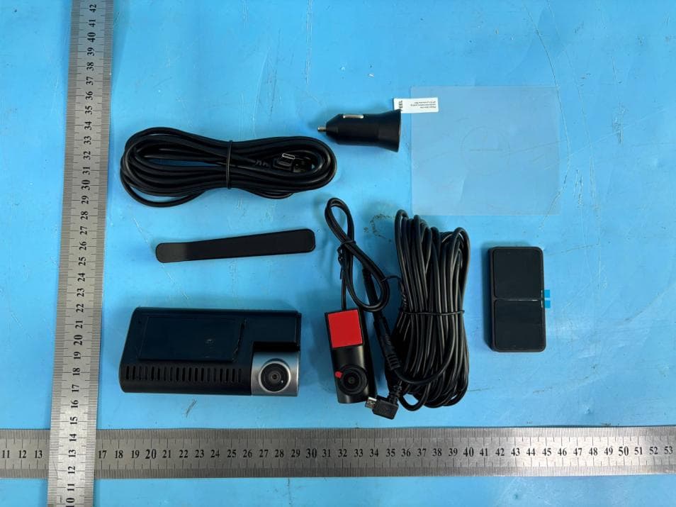
2AZWZ-D11
Sep 26, 2024DASH CAMERA
Equipment Class
DTS - Digital Transmission System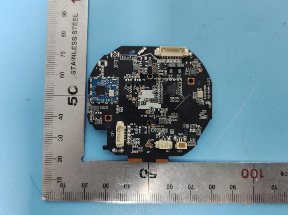
2AZWZ-T6PRO
Sep 04, 2023Dash Camera
Equipment Class
DTS - Digital Transmission System