2BAAR-GC03Projector
Shenzhen Atongmu Technology Co., LTD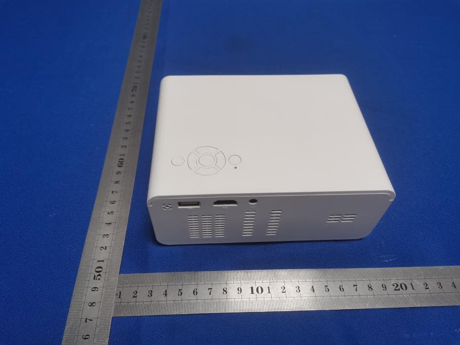
Click to zoom
Application Details
- Equipment Class
- DTS - Digital Transmission System
- Date of Grant
- Feb 27, 2023
- Application Purpose
- Original Equipment
- Date of Application
- Feb 27, 2023
- Equipment Note
- Projector
- Frequency Range
- 2412.00000000 - 2462.00000000
- Country
- China
Documents & Files
Document Text
Text extracted from the exhibit documents filed with the FCC. Open a document above to read the original.
Users Manual
Projector User Guide Due to continuous improvement,actual product may different from the manual,manual is for reference only. 1 Safety Notice: 1.1 Please read use manual carefully before you use projector. 1.2 To prevent the projector from overheating and ensure its reliable operation, it is recommended to install the projector in a well-ventilated place. For example, don't place the projector on a messy coffee table, sofa, bed, etc. Do not place the projector in a narrow space with poor air circulation, such as a bookcase or closet. 1.3 Do not use this projector near water or wet places. To reduce the risk of fire and/or electric shock, do not expose this projector to rain or damp. 1.4 Do not install this product near heat sources, such as radiators, heaters, stoves or other heat-generating equipment. 1.5 Use a dry cloth when cleaning. 1.6 Use only the connectors/accessories specified by the manufacturer. 1.7 If this machine is physically damaged or used carelessly, please do not continue to use this machine.Such as the power cord is damaged, liquid spills on the projector, the projector suffers from rain or damp, foreign objects fall into the projector or internal components are loose, etc. 1.8 Do not let objects or liquids enter the projector. Otherwise, it may come into contact with dangerous voltage points and short-circuit components, resulting in fire or electric shock. 1.9 Pay attention to the safety sign on the projector housing. 1.10 This machine should only be repaired by relevant service personnel. 1.11 Before cleaning the product, turn off the power and unplug the power cord from the AC outlet. Wipe the host shell with a soft dry cloth dipped in neutral detergent. If this product is not used for a long time, unplug the power plug from the AC outlet. 1.12 Do not block the slits and openings for ventilation on the equipment. 1.13 Do not use it under the following conditions:extreme hot, cold or humid environment; an area susceptible to a lot of dust and dirt; Near any equipment that generates a strong magnetic field; direct sunlight. 1.14 When using this product, please keep it out of the reach of children and pets to prevent damage caused by the temperature of the device. 1.15 Do not look directly into the lens of the projector when using this projector. Bright light may harm your eyes. Warning tips: Please follow all warnings, precautions and recommended maintenance items in this user guide. 1.1 Warning-For children under 18 months, it is forbidden to use this product.Children over 18 months should use this product in the presence of parents or adults to avoid accidents. 1.2 Warning-Do not look directly at the projector lens when the light bulb is on. Bright light may hurt your eyes. 1.3 Warning-To reduce the risk of fire or electric shock, do not expose this projector to rain or damp. 1.4 Warning-Do not open or disassemble this projector to avoid electric shock. 1.5 Warning-Before changing the bulb, please completely cool the unit. 1.6 Warning-When turning off the projector, make sure to finish the heat dissipation process before unplugging the power cord. The projector needs 90 seconds to cool down. FCC Warnings This device complies with part 15 of the FCC Rules. Operation is subject to the following two conditions: (1) this device may not cause harmful interference, and (2) this device must accept any interference received, including interference that may cause undesired operation. Any changes or modifications not expressly approved by the party responsible for compliance could void the user's authority to operate the equipment. NOTE: This equipment has been tested and found to comply with the limits for a Class B digital device, pursuant to Part 15 of the FCC Rules. These limits are designed to provide reasonable protection against harmful interference in a residential installation. This equipment generates, uses and can radiate radio frequency energy and, if not installed and used in accordance with the instructions, may cause harmful interference to radio communications. However, there is no guarantee that interference will not occur in a particular installation. If this equipment does cause harmful interference to radio or television reception, which can be determined by turning the equipment off and on, the user is encouraged to try to correct the interference by one or more of the following measures: -- Reorient or relocate the receiving antenna. -- Increase the separation between the equipment and receiver. -- Connect the equipment into an outlet on a circuit different from that to which the receiver is connected. -- Consult the dealer or an experienced radio/TV technician for help. To maintain compliance with FCC’s RF Exposure guidelines, This equipment should be installed and operated with minimum 20cm distance between the radiator and your body: Use only the supplied antenna. 2 Preparation before Light on 1.1 As following picture,connect the power adapter(DC 21V2.5A). 1.2 As following picture,indicator on projector adapter connected. 3 Power on/Power off Press“”button on projector or remote control to switch on the projector. 4 Remote Control Introduction 5 User Interface After projector switched on,following UI will appear after 2-5s starting pictures flash. 6 Focus Locate projector vertical to the projection screen,adjust the keystone wheel till you get clear picture(square pixels appear).You can play some video or display the menu to check focus adjustment. 7 Connection 7.1 Connection Introduction 7.2 Overview Press the “power on”button, it will enter the main interface after the"power on"logo appeared for a few seconds. Main interface review Pre-install application Local player : connect the USB drive to play local video Local player audio Local player audio text Realize multi-screen interaction between mobile phones, computers and other electronic devices and the projector. 7.3 Local Player Connect the USB flash disk driver to the projector and open local p…
Text truncated - open the document above for the full version.
Cover Letter(s)
Shenzhen Atongmu Technology Co., LTD (2023.02.23) Eurofins Electrical and Electronic Testing NA, Inc. 914 West Patapsco Avenue Baltimore, MD 21230 RE: CONFIDENTIALITY REQUEST FOR (Projector / GC03, GC03A, GC05A, GC05B, GC06 / FCC ID: 2BAAR-GC03) To Whom It May Concern: This letter serves as an official request for confidentiality under sections 0.457 and 0.459 of CFR 47. We have requested that the Exhibits Long-Term Confidentiality Short-Term Confidentiality NOTE 2 ID Label/Location No No Attestation Statement No No External Photos No ☐ Block Diagram ☒ ☐ Schematics ☒ ☐ Test Report No No Test Setup Photos No ☐ User’s Manual ☐ NOTE 1 ☐ Internal Photos ☐ NOTE 1 ☐ Parts List / Tune Up ☐ ☐ RF Exposure Info No No Operational Description ☒ ☐ Cover Letter(s) No No SDR Software / Security Info ☐ No required to be submitted with this application be permanently withheld from public review. Above mentioned document contains detailed system and equipment description are considered as proprietary information in operation of the equipment. The public disclosure of above documents might be harmful to our company and would give competitor an unfair advantage in the market. Please contact me if there is any information you may need. Sincerely, Signature: Name: Lu Shen Title: Operations Director
Cover Letter(s)
Shenzhen Atongmu Technology Co., LTD (2023.02.23) Eurofins Electrical and Electronic Testing NA, Inc. 914 West Patapsco Avenue Baltimore, MD 21230 RE: LETTER OF AGENT AUTHORIZATION To Whom It May Concern: We, the undersigned, hereby authorize (Shenzhen CTB Testing Technology Co., Ltd.) to act on our behalf in all matters relating to application for equipment authorization, including the signing of all documents relating to these matters. We also hereby certify that no party to the application authorized hereunder is subject to the denial of benefits, including FCC benefits, pursuant to Section 5301 of the Anti-Drug Abuse Act of 1988, 21 U.S.C.853(a). This agreement expires one year from the current date. Sincerely, Signature: Name: Lu Shen Title: Operations Director
Cover Letter(s)
Shenzhen Atongmu Technology Co., LTD Model Difference Data:2023.02.23 Product description: Projector Model name: GC03, GC03A, GC05A, GC05B, GC06 Trade Name: N/A FCC ID: 2BAAR-GC03 All the model are the same circuit and RF module, except model names . Regards Sincerely Client’s signature : Client’s name / title : Lu Shen(Operations Director) Contact information / address:Room 605,Office A Dong,Qiaohongsheng Wenhua Chuangyiyuan,Yintian Gongyequ,Yantian Shequ,Xixiang Jiedao,Baoan Qu,Shenzhen Shi,Guangdong,518000,China
External Photos
External Photos
ID Label/Location Info
FCC ID LABEL: Label Location: FCC ID: 2BAAR-GC03 Model No.: GC03 This device complies with Part 15 of the FCC Rules. Operation is subject to the following two conditions: (1) This device may not cause harmful interference, and (2) This device must accept any interference received, including interference that may cause undesired operation.
Internal Photos
Internal Photos ANT
RF Exposure Info
FCC §15.247 (i), §2.1091 – RF Exposure FCC ID: 2BAAR-GC03 Applied procedures / limit According to FCC §15.247(i) and §1.1307(b)(1), systems operating under the provisions of this section shall be operated in a manner that ensures that the public is not exposed to radio frequency energy level in excess of the Commission’s guidelines. Limits for Occupational / Controlled Exposure Frequency Range (MHz) Electric Field Strength (E) (V/m) Magnetic Field Strength (H) (A/m) Power Density (S) (mW/ cm 2 ) Averaging Time |E| 2 ,|H| 2 or S (minutes) 0.3-3.0 614 1.63 (100)* 6 3.0-30 1842 / f 4.89 / f (900 / f)* 6 30-300 61.4 0.163 1.0 6 300-1500 F/300 6 1500-100,000 5 6 Note: ƒ is frequency in MHz * = Power density limit is applicable at frequencies greater than 100 MHz Limits for General Population / Uncontrolled Exposure Frequency Range (MHz) Electric Field Strength (E) (V/m) Magnetic Field Strength (H) (A/m) Power Density (S) (mW/ cm 2 ) Averaging Time |E| 2 ,|H| 2 or S (minutes) 0.3-1.34 614 1.63 (100)* 30 1.34-30 824/f 2.19/f (180/f)* 30 30-300 27.5 0.073 0.2 30 300-1500 F/1500 30 1500-100,000 1.0 30 Note: f = frequency in MHz * = Plane-wave equivalent power density MPE PREDICTION Predication of MPE limit at a given distance, Equation from OET Bulletin 65, Edition 97-01 Where: S = power density P = power input to antenna G = power gain of the antenna in the direction of interest relative to an isotropic radiator R = distance to the center of radiation of the antenna,R=20cm Test Result of RF Exposure Evaluation Modes& Channel Freq. (MHz) Tune up Produce power Maximu m peak output power (dBm) Output power to antenna (mW) Antenna Gain (numeric) Power Density (S) (mW/ cm2) Limit (mW / cm2 ) Result 2.4G WIFI 802.11b&2 437 12±1 13 19.9526 1.5849 (2dBi) 0.00629 1 Pass
Test Report
Shenzhen CTB Testing Technology Co., Ltd. Report No.: CTB230216010RFX Report Tel: 4008-707-283Web: http://www.ctb-lab.net Page 1 of 62 TEST REPORT Compiled by: Reviewed by: Approved by: Chen Zheng Arron Liu Bin Mei / Director Note: If there is any objection to the inspection results in this report, please submit a written report to the company within 15 days from the date of receiving the report. The test report is effective only with both signature and specialized stamp. This result(s) shown in this report refer only to the sample(s) tested. Without written approval of Shenzhen CTB Testing Technology Co., Ltd. this report can’t be reproduced except in full. The tested sample(s) and the sample information are provided by the client. “*” indicates the testing items were fulfilled by subcontracted lab. “#” indicates the items are not in CNAS accreditation scope. Product Name: Projector FCC ID: 2BAAR-GC03 Trademark: N/A Model Number: GC03, GC03A, GC05A, GC05B, GC06 Prepared For: Shenzhen Atongmu Technology Co., LTD Address: Room 605, Office A Dong, Qiaohongsheng Wenhua Chuangyiyuan, Yintian Gongyequ, Yantian Shequ, Xixiang Jiedao, BaoanQu, Shenzhen Shi, Guangdong, 518000, China Manufacturer: Shenzhen Atongmu Technology Co., LTD Address: Room 605, Office A Dong, Qiaohongsheng Wenhua Chuangyiyuan, Yintian Gongyequ, Yantian Shequ, Xixiang Jiedao, BaoanQu, Shenzhen Shi, Guangdong, 518000, China Prepared By: Shenzhen CTB Testing Technology Co., Ltd. Address: 1&2/F., Building A, No.26, Xinhe Road, Xinqiao, Xinqiao Street, Bao'an District, Shenzhen, Guangdong, China Sample Received Date: Feb. 01, 2023 Sample tested Date: Feb. 01, 2023 to Feb. 16, 2023 Issue Date: Feb. 16, 2023 Report No.: CTB230216010RFX Test Standards FCC Part15.247 ANSI C63.10:2013 Test Results PASS Remark: This is WIFI-2.4GHz band radio test report. Shenzhen CTB Testing Technology Co., Ltd. Report No.: CTB230216010RFX Report Tel: 4008-707-283 Web: http://www.ctb-lab.net Page 2 of 62 TABLE OF CONTENT Test Report Declaration Page 1. VERSION .......................................................................... 3 2. TEST SUMMARY ................................................................... 4 3. MEASUREMENT UNCERTAINTY ..................................................... 5 4. PRODUCT INFORMATION AND TEST SETUP .......................................... 6 4.1 Product Information .................................................................... 6 4.2 Test Setup Configuration ............................................................... 6 4.3 Support Equipment .................................................................... 6 4.4 Channel List .......................................................................... 7 4.5 Test Mode ............................................................................ 7 4.6 Test Environment ...................................................................... 7 5. TEST FACILITY AND TEST INSTRUMENT USED ....................................... 8 5.1 Test Facility ........................................................................... 8 5.2 Test Instrument Used .................................................................. 8 6. AC POWER LINE CONDUCTED EMISSION ............................................ 10 6.1 Block Diagram Of Test Setup .......................................................... 10 6.2 Limit ................................................................................ 10 6.3 Test procedure ....................................................................... 10 6.4 Test Result .......................................................................... 12 7. RADIATED SPURIOUS EMISSION ................................................... 14 7.1 Block Diagram Of Test Setup .......................................................... 14 7.2 Limit ................................................................................ 14 7.3 Test procedure ....................................................................... 15 7.4 Test Result .......................................................................... 16 8. BAND EDGE AND RF COUNDUCTED SPURIOUS EMISSIONS .......................... 38 8.1 Block Diagram Of Test Setup .......................................................... 38 8.2 Limit ................................................................................ 38 8.3 Test procedure ....................................................................... 38 8.4 Test Result .......................................................................... 39 9. COUDUCTED OUTPUT POWER ..................................................... 46 9.1 Block Diagram Of Test Setup .......................................................... 46 9.2 Limit ................................................................................ 46 9.3 Test procedure ....................................................................... 46 9.4 Test Result .......................................................................... 47 10. 6DB OCCUPIED BANDWIDTH ....................................................... 48 10.1 Block Diagram Of Test Setup ......................................................... 48 10.2 Limit ............................................................................... 48 10.3 Test procedure ...................................................................... 48 10.4 Test Result ......................................................................... 49 11. POWER SPECTRAL DENSITY ...................................................... 54 11.1 Block Diagram Of Test Setup ......................................................... 54 11.2 Limit ............................................................................... 54 11.3 Test procedure ...................................................................... 54 11.4 Test Result ......................................................................... 55 12. ANTENNA REQUIREMENT ................…
Text truncated - open the document above for the full version.
Test Report
深圳旭航通讯科技有限公司 Shenzhen Xuhang Communication Technology Co., Ltd 规格承认书 Antenna manufacturer Shenzhen Xuhang Communication Technology Co., Ltd Manufacturer's address 213-214, 2nd Floor, Building 1, Chenghede Industrial Park, No. 23 Huawang Road, Tongsheng Community, Dalang Street, Longhua District, Shenzhen Name of the supplier WIFI ANT Antenna type XH220075(L=100mm) 客户确认 检验 审核 批准 供方确认 设计 射频 审核 批准 日期:2022年08月13日 电性测试报告 TEST REPORTS 频率 Frequency WIFI(2400~2500MHz) 阻抗 Impedance 50 0hm Nominal 驻波比 V.S.W.R ≤2.0 辐射 Radiation Omni-directional 增益 Gain(Peak) 2dBi 极化方式 Polarization Linear,Vertical 功率 Admitted Power 1W 连接器 Connector I-PEX I Physical Properties 天线材质 Antenna Material PCB 线材类型 Cable Type O.D.1.13mm 工作温度 Operating Temp. -10-+60°C 存储温度 Storage Temp. -10-+70°C 线材颜色 Cable Color Black 匹配电路 Matching Circuits 匹配电路Matching Circuits Element Value Vender E1(0402) E2(0402) 0Ω E3(0402) E4(0402) 0Ω The original matching circuit is unchanged Radiation Pattern 小T Frequency (MHz) Efficiency (%) Peak Gain (dB i ) 2400 43.1 1.77 2410 44.98 1. 33 2420 43.57 1.17 2430 I 44.18 1.34 2440 44.55 1.56 24S0 45.83 2.00 2460 ! 46.48 1.69 2470 46.31 1.42 2480 45.7 1.03 2490 44.19 1.29 2S00 41.61 1.14 G ain table of Anten na Antenna assembly position As shown in the figure: the antenna is assembled at the arrow:
Test Setup Photos
Radiated Emission Below 1G Above 1G Conducted emissions
Contact Information
Applicant
Owen Hu
Technical Contact
Shenzhen Atongmu Technology Co., LTDLu Shen
[email protected]15989509709
Room 605,Office A Dong,Qiaohongsheng Wenhua Chuang · Shenzhen Shi,Guangdong, · China
Test Firm
Shenzhen CTB Testing Technology Co., Ltd.Rita Xiao
[email protected]86-13538218145
Technical Specifications
| # | Rule Parts | Frequency Range | Power Output |
|---|---|---|---|
| 1 | 15C | 2.41 GHz - 2.46 GHz | 19.07 mW |
Other Applications from Shenzhen Atongmu Technology Co., LTD
2BAAR-AE261
Aug 10, 2026Projector
Equipment Class
DTS - Digital Transmission System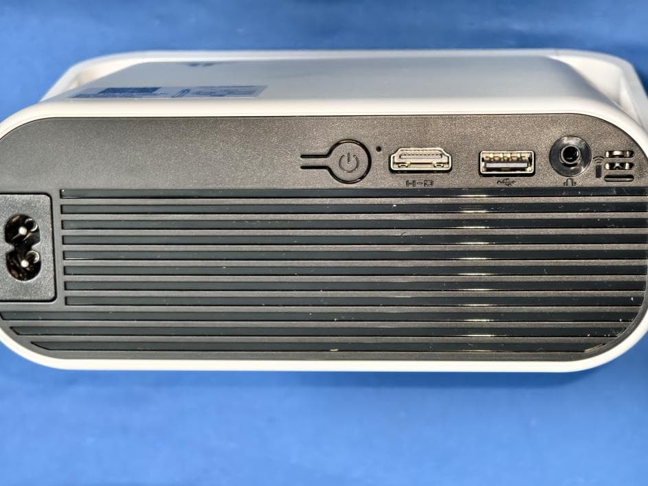
2BAAR-AE211
Mar 18, 2026Projector
Equipment Class
DTS - Digital Transmission System2BAAR-M269A
Aug 05, 2024Projector
Equipment Class
DSS - Part 15 Spread Spectrum Transmitter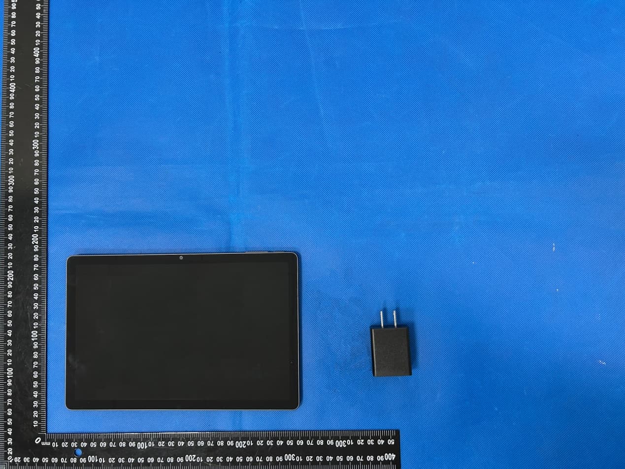
2BAAR-F45A
Feb 20, 2024Tablet PC
Equipment Class
DTS - Digital Transmission System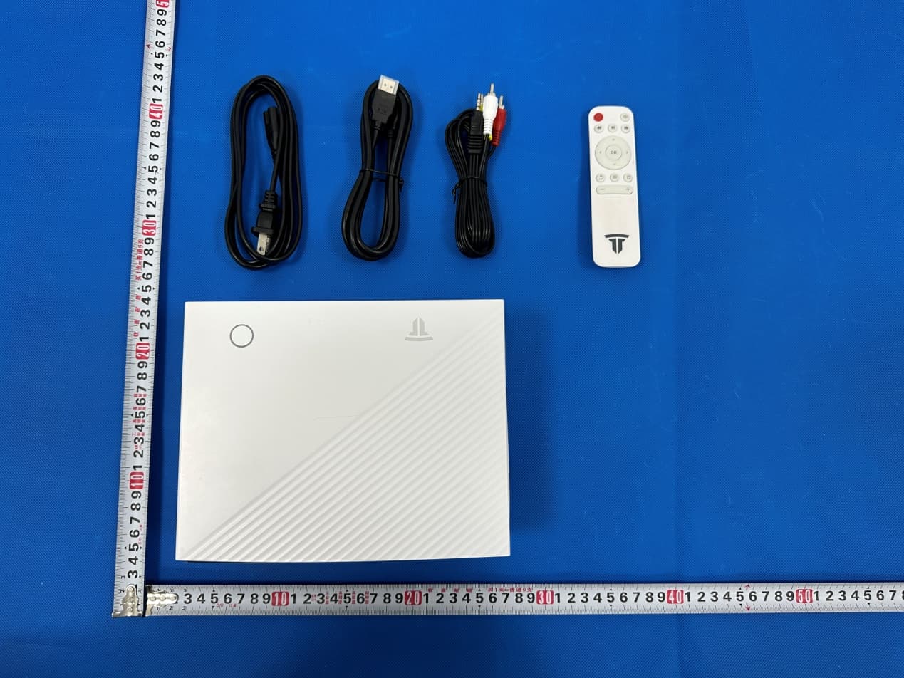
2BAAR-GC05
Sep 25, 2023projector
Equipment Class
NII - Unlicensed National Information Infrastructure TX