2BCK5TLV10Tedee Lock PRO
Tedee Sp. z o.o.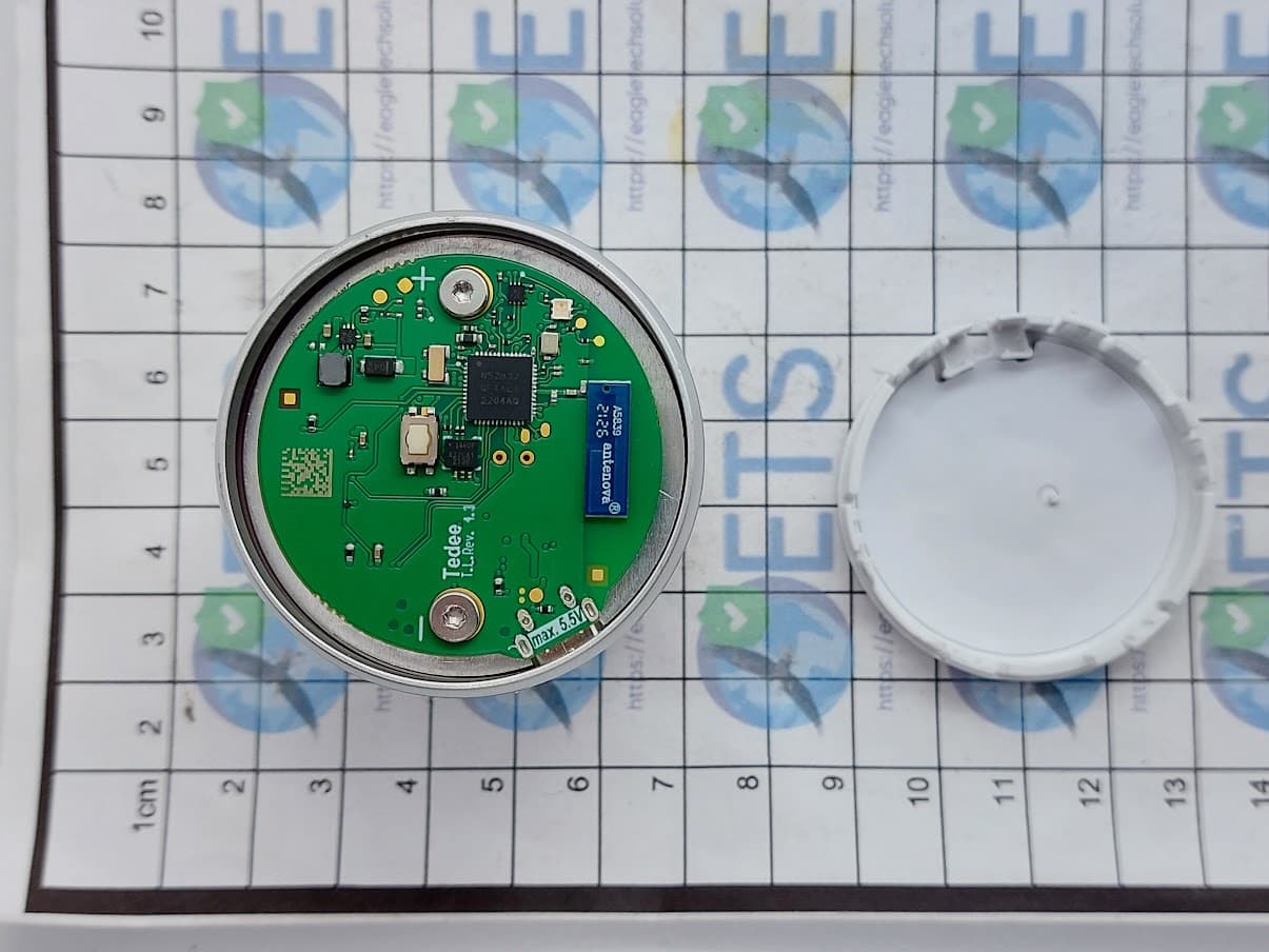
Click to zoom
Application Details
- Equipment Class
- DTS - Digital Transmission System
- Date of Grant
- Nov 01, 2023
- Application Purpose
- Original Equipment
- Date of Application
- Nov 01, 2023
- Equipment Note
- Tedee Lock PRO
- Frequency Range
- 2402.00000000 - 2480.00000000
- Company
- Tedee Sp. z o.o.
- Country
- Poland
Documents & Files
Document Text
Text extracted from the exhibit documents filed with the FCC. Open a document above to read the original.
Users Manual
tedee lock | page 1www.tedee.com INSTALLATION GUIDE AND USER MANUAL tedee lock TLV1.0 and TLV1.1 Read installation guide and user manual and learn how to use your device in a safe and proper manner. EN page 2 | tedee lockwww.tedee.com table of contents table of contents quick start with tedee lock safety information safety guidelines / warnings charging and maintenance guidelines/warnings set of items – what’s in the box? activation code setup - 3 easy steps step 1: install tedee lock step 2: download tedee app, create new account, and log in step 3: use tedee app to activate and calibrate your tedee lock charging tedee lock deinstallation of tedee lock factory reset additional and technical information technical specifications radio frequency micro USB Cable power supply, battery and charging software LED signals legal / environmental notes warranty technical support your activation code Page 2 Page 3 Page 4 Page 4 Page 5 Page 7 Page 8 Page 9 Page 9 Page 12 Page 13 Page 14 Page 15 Page 16 Page 17 Page 17 Page 18 Page 18 Page 19 Page 19 Page 20 Page 22 Page 22 Page 23 Page 24 tedee lock | page 3www.tedee.com Page 2 Page 3 Page 4 Page 4 Page 5 Page 7 Page 8 Page 9 Page 9 Page 12 Page 13 Page 14 Page 15 Page 16 Page 17 Page 17 Page 18 Page 18 Page 19 Page 19 Page 20 Page 22 Page 22 Page 23 Page 24 quick start with tedee lock tedee lock setup - go to page 9 3 easy steps Tedee lock is a smart door lock that can be fitted to GERDA modular cylinder or any other euro-profile cylinder using a special adapter. Tedee smart lock allows you to unlock the door, share access, and check all activities remotely. This booklet will give you an overview of the ba- sic features of tedee lock and will help you walk through the setup in three easy steps. INSTALL tedee lock GET tedee app ACTIVATE and CALIBRATE your lock 12 3 page 4 | tedee lockwww.tedee.com safety information safety guidelines / warnings Do not Do not open, modify or disassemble your device. Do not self-service any part of the device. Do not immerse device in any liquid or expose it to moisture. Do not use the device near extreme heat source or open fire. Do not use the device in an environment of a high humidity or dust levels, as well as pollution degree II. Do not insert any conductive objects in device openings and gaps. The device should not be used by children without adult supervision. The device cannot be used as the only mean of access control to rooms or premises that require increased access control. Do If repairs are required, please contact tedee technical support. Use only power supply devices provided or recommended by tedee. Read the installation guide and learn how to start working with your device, how to add it to your tedee app and how to pair it with other tedee devices. You can also follow the link: www.tedee.com/installation-guide Moving parts The device contains moving parts. When operating the device remotely, it is not recommended to keep your hands on the housing. WARNING: Read all safety guidelines and warnings. Failure to follow the guidelines and warnings may result in electric shock, fire, and / or serious injury. tedee lock | page 5www.tedee.com Other information This device is safe to use under normal and reasonably foreseeable misuse operating code of conduct. If you notice any signs of errors or hardware malfunction, contact tedee technical sup- port for help. In such case this device should be returned to tedee for necessary repairs under the warranty conditions. Any changes or modifications to the device’s hardware or software which are not approved, recommended, or provided by tedee may void your warranty. charging and maintenance guidelines/warnings Battery - please read all precautions before use Your product is powered by a rechargeable LiPo battery. LiPo Batteries used in this product may present risk of fire or chemical burn if mistreated. LiPo Batteries may explode if damaged. Hot or cold environment may reduce the capacity and lifetime of the battery. A fully charged battery will lose its charge over time when left unused. For the best performance, the battery needs to be charged at least every 3 months. Do not dispose as household waste or in a fire as they may explode. If, for any reason, the battery is damaged and the electrolyte (liquid leakage from the device) is leaking, exposure to the substance must be kept to a minimum and: If swallowed, rinse your mouth and seek medical advice as soon as possible. In case of contact with skin, wash with plenty of water. If skin irritation or rash occurs, consult a doctor. In case of contact with eyes, carefully rinse eyes with water for several minutes. Contact a doctor. Do not leave devices with LiPo battery unattended during charging. Avoid direct contact with a leaky/damaged battery. This is particularly true if liquid leaking from the device occurs. Avoid contact with liquid, ensure airflow in the room, and report the fault to tedee's customer service department for further safe handling. Do not insert any conductive objects in device openings and gap – it may cause short-circuits. Dispose of batteries according to your local regulations. Please recycle when possible. Information about the battery level is available in the tedee app. Do not leave a fully charged battery connected to a charger - overcharging may shorten its lifetime. page 6 | tedee lockwww.tedee.com Neither Tedee Sp. z o.o. nor our retailers assume any liability for failures to comply with these warnings and safety guidelines. By purchasing this device, the buyer assumes all risks associat- ed with LiPo batteries. If you do not agree with these conditions, return the device immediately before use. Batteries in tedee lock are not interchangeable. Do not remove or replace the battery in your device. Any attempt to do so is risky and may result in product damage and / or injury. Additional instructions for professional facilities dea…
Text truncated - open the document above for the full version.
Attestation Statements
Contact us: www.tedee.com [email protected] (+48) 22 185 78 18 Tedee Sp. z o.o. Karola Bohdanowicza 21/57 02-127 Warszawa POLAND CFR 47 §2.911 (d)(5) Attestation Date: 08-17-2023 FCC ID: 2BCK5TLV10 To: Federal Communications Commission 7435 Oakland Mills Road Columbia, MD 21046 USA 1. Tedee Sp. z o.o. (“the applicant”) certifies that the equipment for which authorization is sought is not “covered” equipment prohibited from receiving an equipment authorization pursuant to section 2.903 of the FCC rules. 2. Tedee Sp. z o.o. (“the applicant”) certifies that, as of the date of the filing of the application, the applicant is not identified on the Covered List as an entity producing “covered” equipment and is not an affiliate or subsidiary of an entity identified on the Covered List. Sincerely yours, Name: Wojciech Wojas Job Title: Compliance Counsel Company Name: Tedee Sp. z o.o.
Attestation Statements
UL International (UK) LtdULID-018088 issue 1 CFR 47 §2.911 (d)(7) Agent Designation Attestation Date: 10-09-2023 FCC ID: 2BCK5TLV10 To:Federal Communications Commission 7435 Oakland Mills Road Columbia, MD 21046 USA Tedee(“the applicant”)as required by section 2.911(d)(7), designatesthe followingagent, located in the United States,for purposes of acting as the applicant’s agent for service of process. The applicant acknowledges that they will maintain an agent for no less than one year after the grantee has terminated all marketing and importation or the conclusion of any Commission-related proceeding involving the equipment. The applicant further acknowledges their responsibility to inform the FCC whenever the agent information changes. U. S. Agent Information: Robert Jablonski Recharge Consulting LLC 13809 Research Blvd STE 500, Austin, TX 78750 [email protected] Sincerely yours, Name:Wojciech Wojas Job Title:Legal & Compliance Counsel Company Name:Tedee
Attestation Statements
UL International (UK) LtdULID-018088 issue 1FCC Agent Attestation letter template CFR 47 §2.911 (d)(7) FCC US Agent Letter of Attestation Date: 10-09-2023 FCC ID: 2BCK5TLV10 To:Federal Communications Commission 7435 Oakland Mills Road Columbia, MD 21046 USA FCC US Agent Recharge Consulting LLC FRN: 0034332874 Robert Jablonski 13809 Research Blvd STE 500, Austin, TX 78750 [email protected] This letteris to confirm that we have accepted the responsibility to act as US Agent on behalf of Tedee Sp. z o. o.(“the applicant”) for the above referenced FCC ID. Weare aware of the requirements and responsibilities of the applicant’s agent for service of process as outlined in the FCC section 2.911(d)(7)and Report and Order FCC 22-84 paragraph 63. Sincerely yours, Robert Jablonski President Recharge Consulting LLC
Cover Letter(s)
Contact us: www.tedee.com [email protected] (+48) 22 185 78 18 Tedee Sp. z o.o. Karola Bohdanowicza 21/57 02-127 Warszawa POLAND 08.17.2023 Telecommunication Certification Body UL International (UK) Ltd Units 1-3, Horizon Wade Road Kingsland Business Park Basingstoke Hampshire RG24 8AH United Kingdom Subject: Authorisation Letter To whom it may concern This is to certify that Tedee Sp. z o.o. hereby authorises UL International (UK) Ltd. to act as the TCB for the application of the Tedee Lock PRO, TLV1.0, FCC ID: 2BCK5TLV10 to the FCC. We certify that we are not subject to a denial of Federal benefits, that include FCC benefits, pursuant to Section 5301 of the Anti-Drug Abuse Act of 1988, 21 U.S.C. § 862 because of a conviction for possession or distribution of a controlled substance. See 47 CFR 1.2002(b) for the definition of a "party" for these purposes. Yours faithfully, Name: Wojciech Wojas Job Title: Compliance Counsel Company Name: Tedee Sp. z o.o.
Cover Letter(s)
Contact us: www.tedee.com [email protected] (+48) 22 185 78 18 Tedee Sp. z o.o. Karola Bohdanowicza 21/57 02-127 Warszawa POLAND 15. 09.2023 Telecommunication Certification Body UL International (UK) Ltd Units 1-3, Horizon Wade Road Kingsland Business Park Basingstoke Hampshire RG24 8AH United Kingdom Subject: Permanent Confidentiality Request Certification Application FCC ID: FCC ID: 2BCK5TLV10 To w hom it may concern Pursuant to Sections 0.457(d) and 0.459 of CFR 47, Tedee Sp. z o.o. request that the following information, provided to support the FCC application for the Tedee Lock PRO, TLV1.0, FCC ID: 2BCK5TLV10 to be held permanently confidential: •Schematics •Block Diagrams •Operational Description The above material contains trade secrets not customarily released to public that are judged to have the potential to cause detriment to the applicant and provide unjustified benefits to its competitors. This information should not be available for public disclosure for an indefinite period of time. Yours faithfully Name: Wojciech Wojas Job Title: Compliance Counsel Company Name: Tedee Sp. z o.o.
RF Exposure Info
RF Exposure Analysis FCC ID: 2BCK5TLV10 Analysis for FCC portable use Standalone SAR test exclusion considerations are defined in KDB 447498D01 (v06) Chapter 4.3.1 where the 1-g head or body and 10-g extremity SAR exclusion threshold is defined by the following formula: [(max. power of channel, including tune-up tolerance, mW)/(min. test separation distance, mm)] *[√f(GHz)] ≤ 3.0 for 1-g SAR and ≤ 7.5 for 10-g extremity SAR •f(GHz) is the RF channel transmit frequency in GHz •Power and distance are rounded to the nearest mW and mm before calculation •The result is rounded to one decimal place for comparison For the Lock PRO: The Operating frequency is 2402 –2480MHz The maximum conducted output power is -4.0 dBm (0.4mW). Applying the above data using the given KDB 447498 D01 formula, andapplying aminimum separation distance of 5mm, the following results: (0.4mW / 5 mm) x √2.48GHz = 0.13(i.e.: ≤ 3.0 for 1-g SAR and ≤ 7.5 for 10-g extremity SAR) This demonstrates the Lock PRO meets the criteria for 1-g head/ body and 10-g extremity SAR test exemption.
Test Report
UL International (UK) LTD Unit 1-4 Horizon, Kingsland Business Park, Wade Road, Basingstoke, Hampshire, RG24 8AH, UK Telephone: +44 (0)1256 312000 Facsimile: +44 (0)1256 312001 TEST REPORT Test Report No. : UL-RPT-RP14880601-1916A Customer : Tedee Sp. z.o.o. Model No. : TLV1.0 FCC ID : 2BCK5TLV10 Technology : Bluetooth – Low Energy Test Standard(s) : FCC Parts 15.207, 15.209(a) & 15.247 Test Laboratory : UL International (UK) Ltd, Basingstoke, Hampshire, RG24 8AH, United Kingdom 1. This test report shall not be reproduced except in full, without the written approval of UL International (UK) Ltd. 2. The results in this report apply only to the sample(s) tested. 3. The sample tested is in compliance with the above standard(s). 4. The test results in this report are traceable to the national or international standards. 5. Version 1.0. Date of Issue: 23 October 2023 Checked by: Ben Mercer Lead Project Engineer, Radio Laboratory Company Signatory: Sarah Williams RF Operations Leader, Radio Laboratory The Bluetooth ® word mark and logos are owned by the Bluetooth SIG, Inc. and any use of such marks by UL International (UK) Ltd is under licence. Other trademarks and trade names are those of their respective owners. TEST REPORT SERIAL NO: UL-RPT-RP14880601-1916A VERSION 1.0 ISSUE DATE: 23 OCTOBER 2023 Page 2 of 38 Customer Information Company Name: Tedee Sp. z.o.o. Address: UI. Karola Bohdanowicza 21/57, 02-127 Warsaw, Poland Report Revision History Version Number Issue Date Revision Details Revised By 1.0 23/10/2023 Initial Version Ben Mercer TEST REPORT SERIAL NO: UL-RPT-RP14880601-1916A VERSION 1.0 ISSUE DATE: 23 OCTOBER 2023 Page 3 of 38 Table of Contents Customer Information ................................................................................................................... 2 Report Revision History ................................................................................................................ 2 Table of Contents ........................................................................................................................... 3 1 Attestation of Test Results ........................................................................................................ 4 1.1 Description of EUT 4 1.2 General Information 4 1.3 Summary of Test Results 5 1.4 Deviations from the Test Specification 5 2 Summary of Testing ................................................................................................................... 6 2.1 Facilities and Accreditation 6 2.2 Methods and Procedures 6 2.3 Calibration and Uncertainty 7 2.4 Test and Measurement Equipment 8 3 Equipment Under Test (EUT) ................................................................................................... 10 3.1 Identification of Equipment Under Test (EUT) 10 3.2 Modifications Incorporated in the EUT 10 3.3 Additional Information Related to Testing 11 3.4 Description of Available Antennas 11 3.5 Description of Test Setup 12 4 Test Results ............................................................................................................................... 16 4.1 Transmitter Minimum 6 dB Bandwidth 16 4.2 Transmitter Maximum Peak Output Power 19 4.3 Transmitter Radiated Emissions <1 GHz 24 4.4 Transmitter Radiated Emissions >1 GHz 26 4.5 Transmitter Band Edge Radiated Emissions 29 5 AC Power Line Conducted Emissions Test Results ............................................................. 34 5.1 Transmitter AC Conducted Spurious Emissions 34 TEST REPORT SERIAL NO: UL-RPT-RP14880601-1916A VERSION 1.0 ISSUE DATE: 23 OCTOBER 2023 Page 4 of 38 1 Attestation of Test Results 1.1 Description of EUT The equipment under test was a smart lock for accessing doors. 1.2 General Information Specification Reference: 47CFR15.247 Specification Title: Code of Federal Regulations Volume 47 (Telecommunications): Part 15 Subpart C (Intentional Radiators) – Section 15.247 Specification Reference: 47CFR15.207 & 47CFR15.209 Specification Title: Code of Federal Regulations Volume 47 (Telecommunications): Part 15 Subpart C (Intentional Radiators) – Sections 15.207 and 15.209 Site Registration: FCC: 685609 FCC Lab. Designation No.: UK2011 Location of Testing: Unit 3 Horizon, Wade Road, Kingsland Business Park, Basingstoke, Hampshire, G24 8AH, United Kingdom Test Dates: 27 September 2023 to 19 October 2023 TEST REPORT SERIAL NO: UL-RPT-RP14880601-1916A VERSION 1.0 ISSUE DATE: 23 OCTOBER 2023 Page 5 of 38 1.3 Summary of Test Results FCC Reference (47CFR) Measurement Result Part 15.247(a)(2) Transmitter Minimum 6 dB Bandwidth Part 15.247(b)(3) Transmitter Maximum Peak Output Power Part 15.247(e) Transmitter Power Spectral Density Note 1 Part 15.247(d) & 15.209(a) Transmitter Radiated Emissions Part 15.247(d) & 15.209(a) Transmitter Band Edge Radiated Emissions Part 15.207 Transmitter AC Conducted Emissions Key to Results = Complied = Did not comply Note(s): 1. In accordance with ANSI C63.10 Section 11.10.1, PSD measurements are not required if the maximum conducted output power is less than the PSD limit of 8 dBm / 3 kHz. The PSD level is therefore deemed be equal to the measured output power. 1.4 Deviations from the Test Specification For the measurements contained within this test report, there were no deviations from, additions to, or exclusions from the test specification identified above. TEST REPORT SERIAL NO: UL-RPT-RP14880601-1916A VERSION 1.0 ISSUE DATE: 23 OCTOBER 2023 Page 6 of 38 2 Summary of Testing 2.1 Facilities and Accreditation The test site and measurement facilities used to collect data are located at Unit 3 Horizon, Wade Road, Kingsland Business Park, Basingstoke, Hampshire, RG24 8AH, United Kingdom. The following table identifies which facilities were utilised for radiated emission measurements documented in this report. Specific facilities are also identified in the test results sections. Site 1 X Site 2 - Site 17 X UL International (UK) Ltd is accredited by the United Kingd…
Text truncated - open the document above for the full version.
Test Report
Antennas for Wireless M2M Applications 1 Product Specification AE020157-O Rufa 2.4 GHz SMD Antenna Part No. A5839 / A5887 gigaNOVA ® Product Specificati on 1 F eatures •Designed for 2.4 GHz applications: Bluetooth ® , Wi-Fi ® (802.11b/ g), ZigBee ® , etc. •Easy to integrate •Low profile design for use with no ground beneath the antenna •High efficiency •Light weight •Intended for SMD mounting •Supplied in tape on reel 2 Description Rufa is intended for use with all 2.4 GHz applications. The antenna uses a ground plane in or der to radiate efficiently, but this ground plane must not extend underneath the antenna itself. The antenna is available in two versions with the feed locations on the right or left h and side of the antenna. 3 A pplications •Mobile phones •PDAs •PNDs •Headsets •PMPs / MP3s •Laptops •PC-Cards •Sensors Antennas for Wireless M2M Applications 2 Product Specification AE020157-O Rufa 2.4 GHz SMD Antenna Part No. A5839 / A5887 4 Part numbers Rufa Left: A5839 Rufa Right: A5887 5 General data Product name Rufa 2.4 GHz A5839 (Left) Part Number A5887 (Right) Frequency 2.4 – 2.5 GHz Polarization Linear Operating temperature -40 ºC to +85 ºC Impedance with matching 50 Ω Weight 0.1 g Antenna type SMD Dimensions 12.8 x 3.9 x 1.1 [mm] 6 E lectrical characteristics Typical performance Conditions Peak gain 2.1 dBi All data measured on Antenova’s reference boards, part numbers A5839-U1 and A5887-U1 Data given for the 2.4 – 2.5 GHz frequency range Average gain -1.2 dBi Average efficiency 75% Maximum Return Loss -11 dB Maximum VSWR 1.8:1 Antennas for Wireless M2M Applications 3 Product Specification AE020157-O Rufa 2.4 GHz SMD Antenna Part No. A5839 / A5887 7 E lectrical performance 7-1 Return Loss 7-2 VSWR 2200 2300 2400 2500 2600 2700 - 40 - 30 - 20 - 10 0 ∇ ∇ [MHz] [dB] 2200 2300 2400 2500 2600 2700 1 2 3 4 5 ∇ ∇ [MHz] Antennas for Wireless M2M Applications 4 Product Specification AE020157-O Rufa 2.4 GHz SMD Antenna Part No. A5839 / A5887 X 7-3 Antenna patterns Z Y XY plane ZY pl ane XZ pl ane Patterns show combin ed polarisations measured on reference board A5839-U1 Antennas for Wireless M2M Applications 5 Product Specification AE020157-O Rufa 2.4 GHz SMD Antenna Part No. A5839 / A5887 8 A ntenna dimensions Rufa Left Rufa Right LWH LengthWidthHeight 12.8 ± 0.2 3.9 ± 0.2 1.1 ± 0.2 Dimensions in mm 9 A ntenna footprint Rufa Left (Part No: A5839) Rufa Right (Part No: A5887) * CAD files of the antenna footprint are available from A ntenova M2M on request. Please contact [email protected] for further details. ISKJNLO 1.0 ± 0.1 2.0 ± 0.1 8.1 ± 0.1 3.7 ± 0.1 1.3 ± 0.1 2.4 ± 0.1 0.5 ± 0.1 Dimensions in mm Antennas for Wireless M2M Applications 6 Product Specification AE020157-O Rufa 2.4 GHz SMD Antenna Part No. A5839 / A5887 10 E lectrical i nterface 10-1 Transmission lines •All transmission lines should be designed to have a characteristic impedance of 50 Ω •The length of the tr ansmission lines should be kept to a minimum •Any other parts of the RF system like transceivers, power amplifiers, etc, should also be desig ned to have an impedance of 50 Ω Once the material for the PCB has been chosen (PCB thickness and dielectric constant), a coplanar transmission line can easily be designed usin g any of the commercial software packages f or transmission line desig n. For the chosen PCB thickness, copper thickness and substrate dielectric constant, the program will calculate the appropriate tr ansmission line width and gaps on either si de o f t he track so the characteristic impedance of t he coplanar transmission line is 50 Ω. 10-2 Matching circuit The antenna requires a matching circuit that must be optimized for each customer’s product. The matching circuit will require up to three components and the following p ad layout should be desig ned into the device so the correct circuit can be insta lled: The antenna feed pad and the antenna ground pad are indicated in the drawing above. Additional pads are for mechanical attachment only and should not be grounded. Antennas for Wireless M2M Applications 7 Product Specification AE020157-O Rufa 2.4 GHz SMD Antenna Part No. A5839 / A5887 In addition to the matching circuit, a separate DC blocking capacitor will also be required between the radio and the antenna matching circuit. Note: The component values for the matching circuit will vary depending on the size of the PCB and surrounding components. The impedance of the antenna should be measured before selecting suitable matching components. Antenova M2M offers this service on request. Contact [email protected] for further information. 10-3 Antenna placement Antenova M2M strongly recommends placing the antenna near the edge of the board. Maximum antenna performance is achieved by placing the antenna towards one of the corners of the PCB and with the feed point of the antenna as close to same corner of the PCB as possible. Additional ground and components near the antenna should be at a distance of at least 2 mm. Where possible the antenna should be clear of ground from both sides, although the antenna can work well with a minimum clearance of D ≥ 2 mm as shown in the drawing above. Antennas for Wireless M2M Applications 8 Product Specification AE020157-O Rufa 2.4 GHz SMD Antenna Part No. A5839 / A5887 10-4 Reference boards The reference boards have been designed for evaluation purposes of Rufa 2.4 GHz and they include a SMA female connector Rufa Left Rufa Right Dimensions in mm To order a reference board contact [email protected]. Antennas for Wireless M2M Applications 9 Product Specification AE020157-O Rufa 2.4 GHz SMD Antenna Part No. A5839 / A5887 11 Soldering This antenna is suitable for lead free soldering. The reflow profile should be adjusted to suit the device, oven and solder paste, while observing the following conditions: - The maximum temperature should not exceed 240 ºC - However for lead free soldering, a maximum temperature of 255 ºC for no more than 20 seconds is perm…
Text truncated - open the document above for the full version.
Test Setup Photos
Tedee Sp. z.o.o. FCC ID: 2BCK5TLV10 UL-RPT-RP14880601-1916 Test Setup Photographs for the TLV1.0 1. Radiated Emissions 1.1 Configuration 1: < 30 MHz Photo 1 Photo 2 Tedee Sp. z.o.o. FCC ID: 2BCK5TLV10 UL-RPT-RP14880601-1916 1.2 Configuration 2: 30 MHz to 1 GHz Photo 1 Photo 2 Tedee Sp. z.o.o. FCC ID: 2BCK5TLV10 UL-RPT-RP14880601-1916 1.3 Configuration 3: > 1 GHz Photo 1 Photo 2 Tedee Sp. z.o.o. FCC ID: 2BCK5TLV10 UL-RPT-RP14880601-1916 2. AC Conducted Emissions Photo 1 Photo 2
Contact Information
Applicant
Wojciech Wojas
Technical Contact
Tedee Sp. z o.oWojciech Wojas
[email protected]+48602702758
Karola Bohdanowicza 21/57 Street · Warsaw · Poland
Non-Technical Contact
Tedee Sp. z o.oWojciech Wojas
[email protected]+48602702758
Test Firm
UL International (UK) LtdScott D'Adamo
Technical Specifications
| # | Rule Parts | Frequency Range | Power Output |
|---|---|---|---|
| 1 | 15C | 2.40 GHz - 2.48 GHz | 300.00 µW |
Other Applications from Tedee Sp. z o.o.

2BCK5TLV20
Nov 01, 2023Tedee Lock GO
Equipment Class
DTS - Digital Transmission System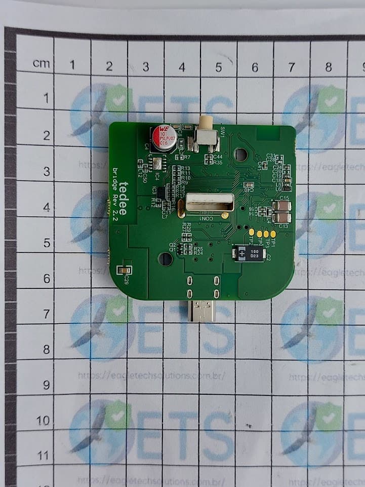
2BCK5TBV10
Nov 01, 2023Tedee Bridge
Equipment Class
DTS - Digital Transmission System