2BDX6-R011VAXIS LATCH EXTENDER
RVLOCK & CO, LLC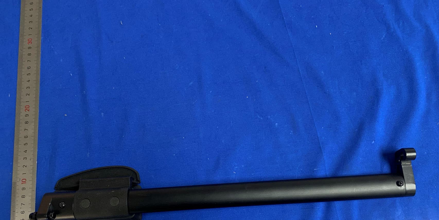
Click to zoom
Application Details
- Equipment Class
- DSC - Part 15 Security/Remote Control Transmitter
- Date of Grant
- Apr 16, 2024
- Application Purpose
- Original Equipment
- Date of Application
- Apr 15, 2024
- Equipment Note
- AXIS LATCH EXTENDER
- Frequency Range
- 433.92500000 - 433.92500000
- Company
- RVLOCK & CO, LLC
- Country
- United States
Documents & Files
Document Text
Text extracted from the exhibit documents filed with the FCC. Open a document above to read the original.
Users Manual
USER MAUAL FOR AXIS LATCH EXTENDER 1. Function description: 1.1. Automatic standby: When there is no signal input for 5 consecutive seconds, the system will automatically enter the power saving mode (less than 1uA); 1.2. Low voltage alarm: When the battery voltage is lower than 2.4 volts, a sound of "beep" will be emitted each time the button is released. 2. Instructions for use: 2.1. Normal Use: Open the door: Enter the password, if the code is correct (no need to press the lock button), a signal of opening is sent with a long "beep", If the password is incorrect, the buzzer will emit 5 short "beeps" after pressing the button for 5 seconds. Then standby. Lock the door: Press the lock button directly (no need to enter the password) , the door closing signal is sent with a long "beep". Note: 1. If the password is 027, then passwords like 27 and 0027 are not to be considered correct. 2. If the digits of the password entered is more than 8, it will be treated as an incorrect password. 3. Change your password: The factory user password is 1234. Press the key 0 and hold on, then press the lock key, At this time, the buzzer emits a long "beep", then release the lock key, release the button 0, and enter password change status: Enter the current password 1234 (such as xxxxx) at this time, press the lock key, Enter a new password, e.g. 28111976 (no more than 8 digits), press the lock key, and enter it again. The new password is 28111976, press the lock key, the password is changed successfully, and the buzzer will emit a long "beep" (this time the button does not emit a signal). Note: If the new password is more than 8 digits or the new password entered twice is inconsistent, it will be prompted password change is wrong, the buzzer makes 5 short "beeps", and the password change is exited. In the password change status, when entering a new password, an empty password is not allowed. 4.Restore the password to the factory status: If the password is forgotten, you can s short wire the circuit board for 5 seconds and with a "beep", the password is restored to the factory status: 1234. 5.FCC Statement Changes or modifications not expressly approved by the party responsible for compliance could void the user's authority to operate the equipment. This equipment has been tested and found to comply with the limits for a Class B digital device, pursuant to Part 15 of the FCC Rules. These limits are designed to provide reasonable protection against harmful interference in a residential installation. This equipment generates uses and can radiate radio frequency energy and, if not installed and used in accordance with the instructions, may cause harmful interference to radio communications. However, there is no guarantee that interference will not occur in a particular installation. If this equipment does cause harmful interference to radio or television reception, which can be determined by turning the equipment off and on, the user is encouraged to try to correct the interference by one or more of the following measures: -- Reorient or relocate the receiving antenna. -- Increase the separation between the equipment and receiver. -- Connect the equipment into an outlet on a circuit different from that to which the receiver is connected. -- Consult the dealer or an experienced radio/TV technician for help This device complies with part 15 of the FCC rules. Operation is subject to the following two conditions (1)this device may not cause harmful interference, and (2) this device must accept any interference received, including interference that may cause undesired operation。
Attestation Statements
Covered Equipment Attestation Letter For Certification Service in the USA Federal Communication Commission Equipment Authorization Division, Application Processing Branch 7435 Oakland Mills Road Columbia, MD 21048 To whom it may concern Pursuant to Section 2.911(d)(5)(i)‐(ii) of the Commission’s Rules (47 C.F.R.) we attest as follows for the product listed below: FCC ID Model name 2BDX6‐R011V R011V We, applicant Company Name: RVLOCK & CO, LLC Address: 1770 WEST 2690 SOUTH WELLSVILLE, UT 84339 USA Phone: +1 435 994 0880 certify that the equipment for which authorization is sought is not “covered” equipment prohibited from receiving an equipment authorization pursuant to section 2.903 of the FCC rules. We certify that, as of the date of the filing of the application, the applicant is not identified on the Covered List as an entity producing “covered” equipment. If you have any questions, please feel free to contact us at the address shown below. Sincerely, Mar.28,2024 Signature Date Printed Name of Signee: CADE HARRIS Company: RVLOCK & CO, LLC Address: 1770 WEST 2690 SOUTH WELLSVILLE, UT 84339 USA Phone: +1 435 994 0880 Email: [email protected]
Attestation Statements
Local Representative Letter For Certification Service in the USA Federal Communications Commission Equipment Authorization Division, Application Processing Branch 7435 Oakland Mills Road Columbia, MD 21048 To whom it may concern Pursuant to Section 2.911(d)(7), of the Commission’s Rules (47 C.F.R.) we attest as follows for the product listed below: FCC ID Model name 2BDX6‐R011V R011V We hereby acknowledge as follows: i. both signees confirm that the point of contact accepts responsibility to act as a US‐ American Representative on behalf of the applicant ii. the point of contact provides the physical U.S. address and email as listed below iii. both parties maintain the requirements of this agreement for no less than one year after the grantee has terminated all marketing and importation or the conclusion of any Commission‐related proceeding involving the equipment. US‐American Point of Contact Applicant/Approval Holder Company Name: GSS SERVICE INC RVLOCK & CO, LLC FRN: 0033500653 0034583633 Contact Name: Michoux Logan CADE HARRIS Address: 6547 N Academy Blvd #2266 Colorado Springs Co 80918 USA 1770 WEST 2690 SOUTH WELLSVILLE, UT 84339 USA Phone: 001‐949‐2990192 or 001‐515‐ 7158284 +1 435 994 0880 Email: [email protected] [email protected]
Cover Letter(s)
Confidentiality Request Letter For Certification Service in the USA Federal Communication Commission Equipment Authorization Division, Application Processing Branch 7435 Oakland Mills Road Columbia, MD 21048 To whom it may concern Pursuant to Paragraphs §0.457 and 0.459 of the Commission’s Rules (47 C.F.R.) and Section §552(b)(4) of the Freedom of Information Act, we request confidentiality for the documentation of the following products: FCC ID Model name 2BDX6‐R011V R011V For the products listed above, we request permanent confidentiality for all applicable exhibits as there are: the Operational Description the Block Diagram the Schematics The above listed exhibits contain trade secrets and proprietary information that could be of benefit to our competitors. If you have any questions, please feel free to contact us at the address shown below. Sincerely, Mar.28,2024 Signature Date Printed Name of Signee: CADE HARRIS / Manager Company: RVLOCK & CO, LLC Address: 1770 WEST 2690 SOUTH WELLSVILLE, UT 84339 USA Phone: +1 435 994 0880 Fax: Email: [email protected]
External Photos
External Photographs FCC ID: 2BDX6-R011V PCB
ID Label/Location Info
Label Sample for FCC ID: 2BDX6-R011V FCC ID: 2BDX6-R011V This device complies with Part 15 of the FCC Rules. Operation is subject to the following two conditions: (1) This device may not cause harmful interference, and (2) This device must accept any interference received, including interference that may cause undesired operation. Size for the label: Product Name : AXIS LATCH EXTENDER Model : R011V FCC ID :2BDX6-R011V
Internal Photos
Internal photographs FCC ID: 2BDX6-R011V Antenna
RF Exposure Info
Radio frequency radiation exposure evaluation: portable devices 1.1 Radio Frequency Exposure Compliance 1.1.1 Electromagnetic Fields RESULT: Pass Test Specification Test item : AXIS LATCH EXTENDER Identification / Type No. : R011V FCC ID : 2BDX6-R011V Test standard : CFR47 FCC Part 2: Section 2.1093 FCC KDB Publication 447498 v06 Measurement Record: EIRP[dBm] = E[dBuV/m] − 95.2 =75.11 – 95.2 =-20.09 dBm Since maximum peak output power of the transmitter is -25.82 dBm ≈0.0098mW < 22mW. Hence the EUT is excluded from SAR evaluation according to FCC KDB Publication 447498 D01 General RF Exposure Guidance v06.
Test Report
Justification statement Applicant: RVLOCK & CO, LLC Address of applicant: 1770 WEST 2690 SOUTH WELLSVILLE, UT 84339 USA Model: R011V Antenna Type: PCB antenna All measurements were performed radiated and therefore additional antenna gain documentation is not required. Transmitter: The thick line of the entire circle shape along the edge of the PCB pointed by the arrow is the transmitting antenna, with a length of 98.04mm and a width of 1.2 mm. Name / Title CADE HARRIS /Manager Company Name:RVLOCK & CO, LLC Company Address:1770 WEST 2690 SOUTH WELLSVILLE, UT 84339 USA Tel: +1 435 994 0880 Fax: Email: [email protected]
Test Report
BSL Technology Co., Ltd. Report No.: BSL231231901605RF Page 1 of 23 FCC Part 15C Measurement and Test Report For RVLOCK & CO, LLC FCC ID: 2BDX6-R011V FCC Rule(s): FCC Part 15.231(a) Product Description: AXIS LATCH EXTENDER Tested Model: R011V Report No.: BSL231231901605RF Tested Date: Dec. 15,2023~Apr.8, 2024 Issued Date: Apr. 8, 2024 Tested By: Lris. Yao / Engineer Reviewed By: Livi. Xiao / EMC Manager Approved & Authorized By: Salon.ouyang/ PSQ Manager Prepared By: BSL Testing Co.,LTD. 1/F, Building B, Xinshidai GR Park, Shiyan Street, Bao'an District, Shenzhen, ShiyanStreet, Bao'an District, Shenzhen,Guangdong,518052,People’s Republic of China Tel: 400-882-9628 Fax: 86- 755-26508703 BSL Technology Co., Ltd. Report No.: BSL231231901605RF Page 2 of 23 TABLE OF CONTENTS 1. GENERAL INFORMATION ................................................................................................................................... 3 1.1 PRODUCT DESCRIPTION FOR EQUIPMENT UNDER TEST (EUT) ............................................................................... 3 1.2 TEST STANDARDS ................................................................................................................................................... 4 1.3 TEST METHODOLOGY ............................................................................................................................................. 4 1.4 TEST FACILITY ....................................................................................................................................................... 4 1.5 EUT SETUP AND TEST MODE ................................................................................................................................. 4 1.5 EUT SETUP AND TEST MODE ................................................................................................................................. 5 1.6 MEASUREMENT UNCERTAINTY .............................................................................................................................. 5 1.7 TEST EQUIPMENT LIST AND DETAILS ..................................................................................................................... 6 2. SUMMARY OF TEST RESULTS ........................................................................................................................... 7 3. ANTENNA REQUIREMENT .................................................................................................................................. 8 3.1 STANDARD APPLICABLE ......................................................................................................................................... 8 3.2 TEST RESULT.......................................................................................................................................................... 8 4. CONDUCTED EMISSIONS .................................................................................................................................... 9 4.1 TEST PROCEDURE ................................................................................................................................................... 9 4.2 BASIC TEST SETUP BLOCK DIAGRAM ..................................................................................................................... 9 4.3 ENVIRONMENTAL CONDITIONS .............................................................................................................................. 9 4.4 TEST RECEIVER SETUP ........................................................................................................................................... 9 4.6 CONDUCTED EMISSIONS TEST DATA .................................................................................................................... 10 5. RADIATED EMISSIONS ....................................................................................................................................... 11 5.1 STANDARD APPLICABLE ....................................................................................................................................... 11 5.2 TEST PROCEDURE ................................................................................................................................................. 12 5.3 CORRECTED AMPLITUDE & MARGIN CALCULATION ............................................................................................ 14 5.4 ENVIRONMENTAL CONDITIONS ............................................................................................................................ 14 5.5 SUMMARY OF TEST RESULTS/PLOTS .................................................................................................................... 14 6. 20DB BANDWIDTH ............................................................................................................................................... 18 6.1 STANDARD APPLICABLE ....................................................................................................................................... 18 6.1 TEST PROCEDURE ................................................................................................................................................. 18 6.2 ENVIRONMENTAL CONDITIONS ............................................................................................................................ 18 6.3 SUMMARY OF TEST RESULTS/PLOTS .................................................................................................................... 18 7. TRANSMISSION TIME ......................................................................................................................................... 19 7.1 STANDARD APPLICABLE ....................................................................................................................................... 19 7.2 TEST PROCEDURE ......................................................................................…
Text truncated - open the document above for the full version.
Test Setup Photos
Test Setup Photos FCC ID: 2BDX6-R011V
Contact Information
Applicant
CADE HARRIS
Test Firm
BSL Testing Co., Ltd.Bill Zhao
[email protected]+86 755 26649703
Technical Specifications
| # | Rule Parts | Frequency Range | Power Output |
|---|---|---|---|
| 1 | 15.231 | 433.925 MHz - 433.925 MHz | - |
Other Applications from RVLOCK & CO, LLC
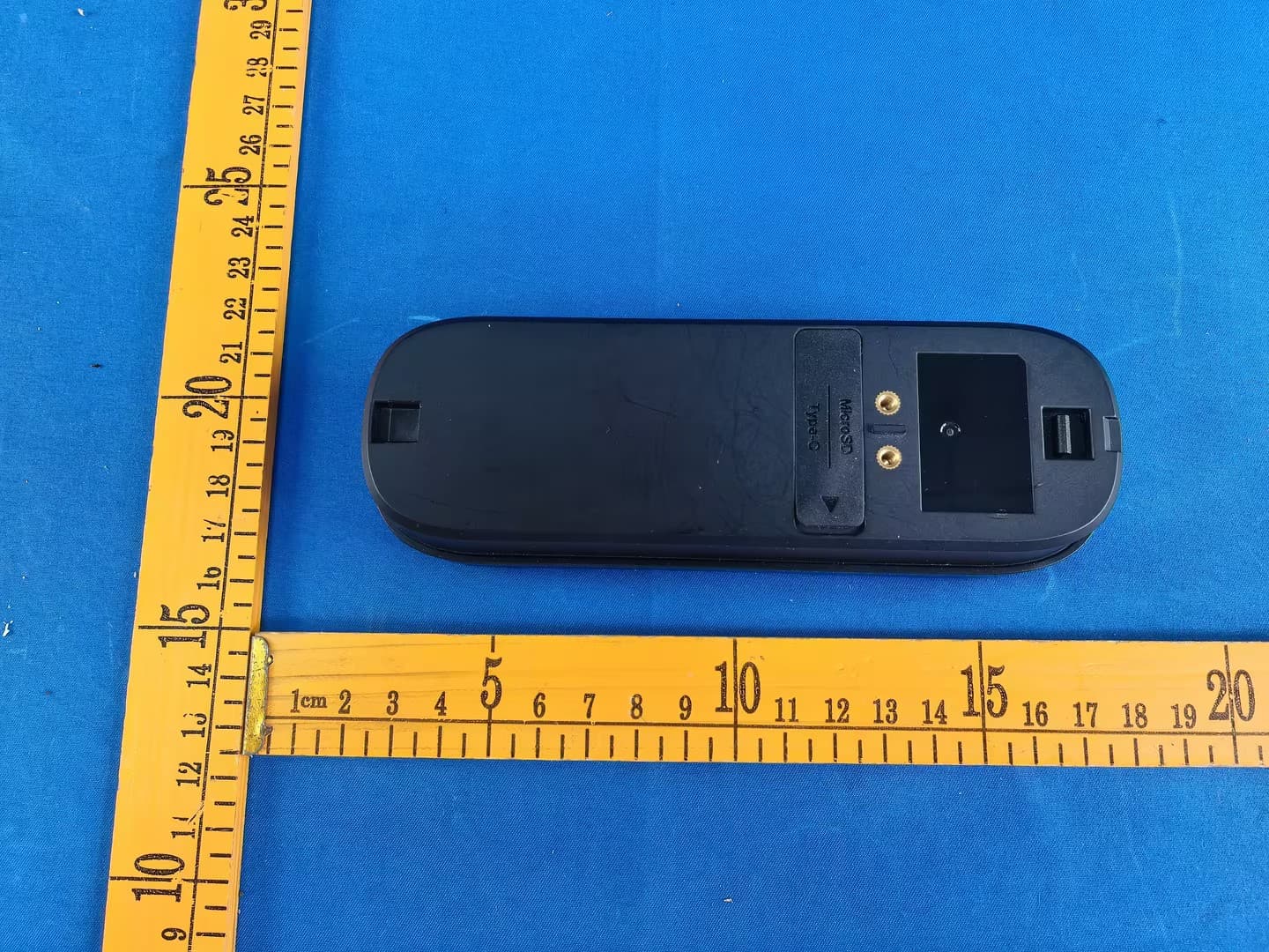
2BDX6-RS1-C01
Jul 02, 2026RVLock Scout Camera
Equipment Class
DTS - Digital Transmission System2BDX6-RS1-T01
Jun 24, 2026Beacon
Equipment Class
DTS - Digital Transmission System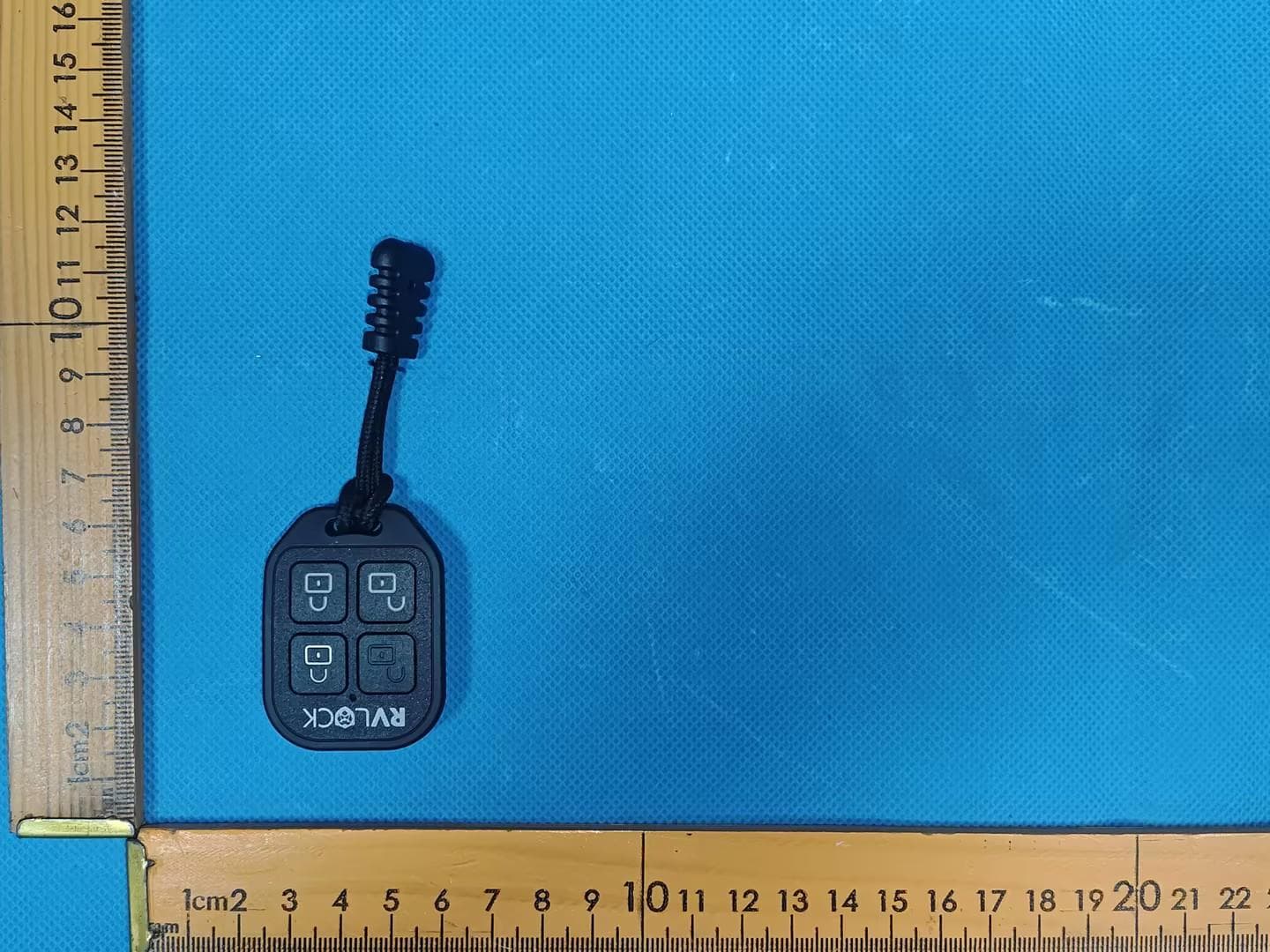
2BDX6-R015V
Feb 02, 2026Key FOB
Equipment Class
DSC - Part 15 Security/Remote Control Transmitter2BDX6-R100V
Apr 14, 2024TREK KEYLESS ENTRY HANDLE
Equipment Class
DTS - Digital Transmission System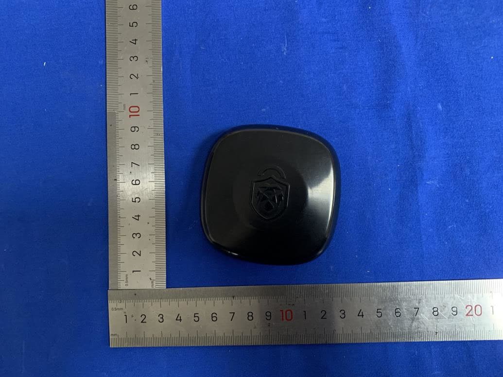
2BDX6-R010V
Apr 02, 2024RV LOCK BT PRO
Equipment Class
DTS - Digital Transmission System