2BFHC-ICON200Base Station of DECT phone
JPL Telecom LLC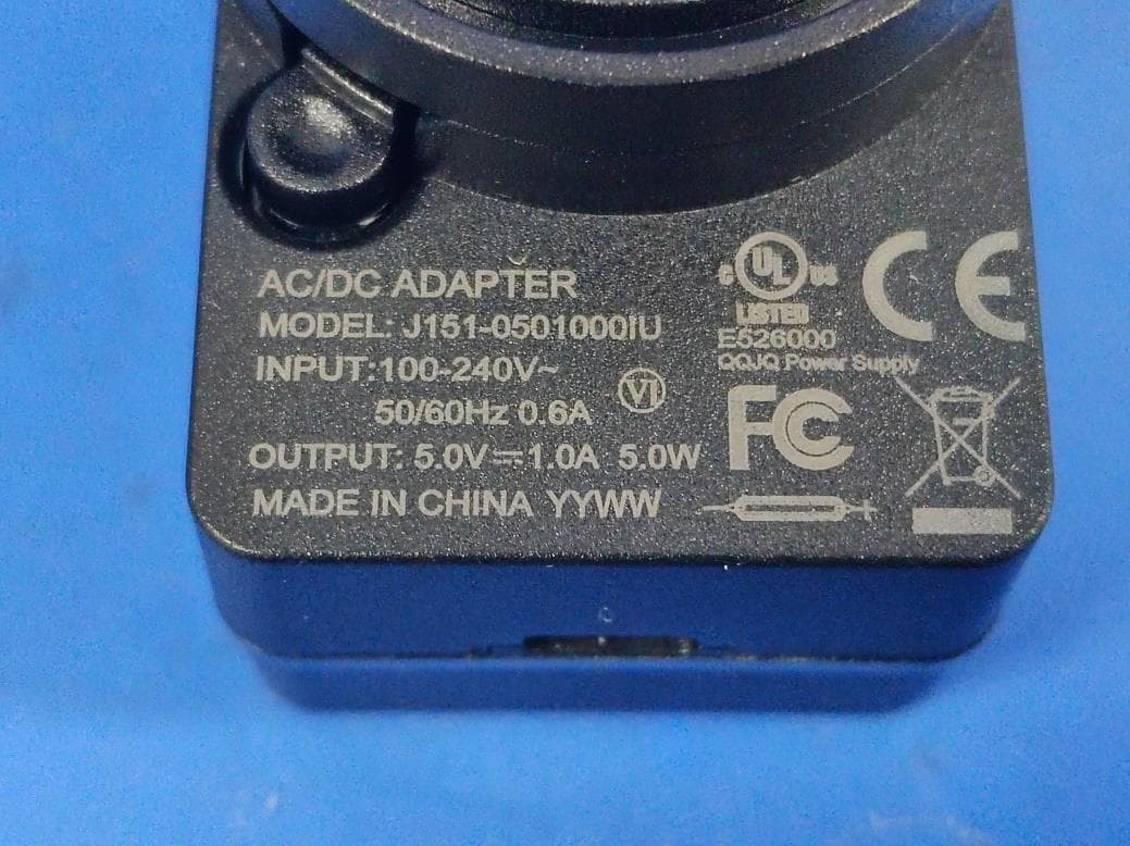
Click to zoom
Application Details
- Equipment Class
- PUB - Part 15 Unlicensed PCS Base Station
- Date of Grant
- Apr 28, 2026
- Application Purpose
- Original Equipment
- Equipment Note
- Base Station of DECT phone
- Frequency Range
- 1921.53600000 - 1928.44800000
- Company
- JPL Telecom LLC
- Country
- United States
Documents & Files
Document Text
Text extracted from the exhibit documents filed with the FCC. Open a document above to read the original.
Users Manual
JPL - Icon 200 User’s Manual Wireless Headset INTRODUCTION Base Station Headset USB-C Cord Telephone Cord Optional Accessories Normal size DL-570 Lifter Electronic Hook Ear Cushion Switch (EHS) What’s included Positioning the Microphone The headset’s microphone boom arm is flexible, so you can gently bend the boom and position it to suit the curve of your face. The ideal placement for the microphone is usually at the tip of your mouth, not in front of it, and about an inch from your face. Be sure that the side of the microphone is pointed toward your mouth. Adjusting earpiece speaker volume To change the earpiece speaker volume: push the volume button up to ‘+’ icon for increasing volume and push down to ‘ - ‘icon for decreasing volume. Mute / Unmute microphone There are two ways to mute and unmute. Pu sh mute button or tilt up microphone boom arm. When the mute is on, the Light indicator at the tip of boom arm turns to red color. For unmute, the color will be changed to blue. Charging headset For charging headset, connect supplied USB- C cable to USB-C port of the headset Or put the headset on the crad le of the base station. When the headset is on charging, the battery level will be shown with different color LED. Base Unit Bluetooth Button& LED This function works when the Bluetooth Option is added. PC/TEL Button& LED This function works for the USB/Tel option model. Mic. Mute Button& LED Touch to mute and unmute Microphone Volume The Icon-200 headset has automatic audio configuration, however, if required, you can adjust the volume level for the microphone. Compatibility Switch Select ‘1’ or’2’ until a dial tone is heard via the telephone connection USB-C Data in & Power Connect USB-C cable for Power and USB Data AUX port Connection for Handset Lifter or EHS Adapter (optional) Telephone Port Connect telephone cord to the headset port or handset port of a telephone / base unit Handset Port Plug Handset cord from the phone to Handset port USB-C PWR For external USB-C power, it can be used. Visual Indicator Audio Indicator Event Sound Effect Speaker /Microphone volume Beep Max/Min Speaker volume Double beep Max/Min microphone volume Double beep Microphone mute/unmute Mute reminder Hook Off / On Setting up the Base Desk Phone with Headset Port Plug the supplied telephone cord into the TEL port of the BASE Unit Connect the telephone cord to the HEADSET port of the desk phone Desk Phone without Headset Port On the desk phone, unplug the handset cable from the phone Plug the handset cable into the HANDSET port on the BASE Plug the telephone cord into the TEL port on the BASE and plug the other end of the telephone cord into the HANDSET port on the desk phone Additional Accessories DL-570 LIFTER The DL-570 LIFTER remotely lifts the desk phone handset to make or answer a call. Electronic Hook Switch (EHS) Adapter EHS Adapter enables an incoming call to be answered or finishing call. EHS is only compatible with certain tele phone systems. In order to determine which telephones are compatible with the EHS feature, please refer to EHS guide or contact your local distributor. Please also refer to your telephone’s user manual for clarification. Operating Instructions - Connect the USB-C cable to USB-C In port at base station. (See Note 1 below ) - Press the Hook On/Off button to make a call - Select compatibility switch ‘1’ or ‘2’ pos ition until you can hear the dial tone - Adjust speaker and microphone volume for comfortable audio level. - Press the Hook On/Off button to end a call Note 1 : Pairing Option 1. - Place the headset on the cradle - Plug USB-C cable to the base station (Pairi ng process is automatically proceeding): Call indicator will be blinking. Option 2. - Touch the mute button for 3 seconds. And the call indicator will be blinking. - Press the ‘mute button’ of the headset until LED of the headset is blinking. - If pairing is completed, you can hear bee p sound and LEDs of base and headset will be off. Trouble Shooting 1. Cannot hear a dial tone . ☞ Check the TEL/PC button. TEL Mote: PC/TEL indicator – ‘OFF’ ☞ Please check the cable connection between Base station and Phone. ☞ Check that the USB-C cable is plugged in. ☞ Please check the compatibility switch. Adju st compatibility switch until you can hear the dial tone. 2. Microphone volume (TX) is low / dead . ☞ Make sure that the microphone (TX) mute function is off. ☞ Check the position of the boom arm and make sure that the microphone is placed as close as possible to your mouth (approx. 2 fingers distance). ☞ Adjust the microphone (TX) volume on the base station. 3. Buzzing sound on the headset ☞ Telephone may not be fully immune to the radio transmission between your headset and base. To overcome this proble m, move the base unit to at least 30 cm/12” away from the phone. 4. Headset echoes ☞ Adjust the telephone’s volume. If necessary, adjust your microphone volume on the headset to a lower setting. 5. EHS doesn’t work with the telephone ☞ Make sure the telephone is compatible with the wireless headset. Refer to the EHS guide. 6. Headset was working, but it has stopped. ☞ Headset may need pairing to the base again. Refer to the ‘ Note 1 ’ on ‘ Operating Instruction ’ ☞ Headset battery may be dead. Return the headset to the cradle on the base unit for charging. FCC Caution This device complies with part 15 of the FCC Rules. Operation is subject to the following two conditions: (1) This device may not cause harmful interference, and (2) this device must accept any interference received, including interference that may cause undesired operation. Any Changes or modifications not expressly approved by the party responsible for compliance could void the user's authority to operate the equipment. Note: This equipment has been tested and found to comply with the limits for a Class B digital device, pursuant to part 15 of the FCC Rules. These limits are designed to provide reasonable protection against harmful interference in a res…
Text truncated - open the document above for the full version.
Attestation Statements
Rev 1/26/2023 JPL Telecom LLC Federal Communications Commission Authorization and Evaluation Division 7435 Oakland Mills Road Columbia, MD 21046 USA Date: 2026-04-21 FCC ID: 2BFHC-ICON200 Ref. #1: Attestation Statements Part 2.911(d)(5)(i) Filing JPL Telecom LLC certifies that the equipment for which authorization is sought is not “covered” equipment prohibited from receiving an equipment authorization pursuant to section 2.903 of the FCC rules. JPL Telecom LLC certifies that the equipment for which authorization is sought does not include cybersecurity or anti-virus software produced or provided by Kaspersky Lab, Inc. or any of its successors and assignees, including equipment with integrated Kaspersky Lab, Inc. (or any of its successors and assignees) cybersecurity or anti-virus software pursuant to DA-24-886 and KDB 986446 D01 Covered Equipment Guidance section B(2a). Device is inherently compliant based on hardware limitations or software controls. or A Software Bill of Materials (SBOM) is provided to the TCB for review, and The end-user or third parties cannot install additional software on this device. Ref. #2: Attestation Statements Part 2.911(d)(5)(ii) Filing JPL Telecom LLC certifies that, as of the date of the filing of the application, the applicant is not identified on the Covered List (as a specifically named entity or any of its subsidiaries or affiliates) as an entity producing “covered” equipment. Applicant: JPL Telecom LLC Address: JPL Telecom LLC 445 W Merritt Avenue MERRITT ISLAND Florida 32953-4760 United States Contact Person: James Clarke Tel.: 3213001141 Email: [email protected] Sincerely, Signature:
Attestation Statements
Attestation Statements Date: 2026-04-21 TO: Federal Communications Commission Authorization and Evaluation Division 7435 Oakland Mills Road Columbia, MD 21046, USA RE: Attestation Statements Part 2.911(d)(7) request for(FCC ID: 2BFHC-ICON200) JPL Telecom LLC, the undersigned, hereby authorize JPL Telecom LLC to act as our designated agent for service of process, JPL Telecom LLC accepts to maintain an agent for no less than one year after the grantee has terminated all marketing and importation or the conclusion of any Commission-related proceeding involving the equipment. JPL Telecom LLC accepts the responsibility to act as designated agent for service of process. Applicant Information: Company name: JPL Telecom LLC Contact Name: James Clarke Address: JPL Telecom LLC 445 W Merritt Avenue MERRITT ISLAND Florida 32953-4760 United States Telephone No: 3213001141 Email: [email protected] FRN: 0034729418 Signature: James Clarke Agent Information: Company Name: JPL Telecom LLC Address:JPL Telecom LLC 445 W Merritt Avenue MERRITT ISLAND Florida 32953-4760 United States FRN: 0034729418 Contact Name: James Clarke Telephone No: 3213001141 Email: [email protected] Signature: James Clarke
Cover Letter(s)
JPL Telecom LLC Office of Engineering Technology Federal Communications Commission 7435 Oakland Mills Road Columbia, MD 21046 USA Date: April 22, 2026 Subject; Request for Confidentiality FCC ID: 2BFHC-ICON200 To Whom It May Concern, Pursuant to the provisions of the Commission’s rules Title 47 Sections §0.457 and §0.459, we are requesting the Commission to withhold the following attachment(s) as confidential documents from public disclosure indefinitely. These documents contain detailed system and equipment descriptions and are considered as proprietary information in operation of the equipment. The public disclosure of these documents might be harmful to our company and would give competitors an unfair advantage in the market. Schematic Diagram Block Diagram Parts List Operational Description Tune-up Procedure SOFTWARE SECURITY REQUIREMENTS FOR U-NII DEVICES In additional to above mentioned documents, in order to comply with the marketing regulations in Title 47 CFR §2.803 and the importation rules in Title 47 CFR §2.1204, while ensuring that business sensitive information remains confidential until the actual marketing of newly authorized devices, we request Short Term Confidentiality of the following attachment(s); External Photos Test Setup Photos Internal Photos User Manual For 45 days, pursuant to Public Notice DA 04-1705. OR For 180 days pursuant to KDB 726920 D01. It is our understanding that all measurement test reports, FCC ID label format and correspondence during the certification review process cannot be granted as confidential documents and this information will be available for public review once the grant of equipment authorization is issued. Sincerely, Signature: Name: James Clarke Title: Manager
Cover Letter(s)
Effective Date: April 2, 2020 QSF 7.6.4-8 – Agent Authorization Letter Template Page 1 of 1 Revision Date: Revision: 0 JPL Telecom LLC Date:2026-04-21 Product Model Number: JPL-Icon 200, JPL-Icon 200-B1, JPL-Icon 200-B2, JPL-Icon 200-M1, JPL-Icon 200- M2 FCC ID:2BFHC-ICON200 To whom it may concern, Re: Product Certification Representative Authorization Letter We authorize QAI Laboratories Ltd. 3980 North Fraser Way, Burnaby B.C. Canada V5J 5K5 to act on our behalf on all matters concerning the above named equipment. This shall include the following: • Testing • Approval applications and procedures We declare that QAI Laboratories Ltd. is allowed to forward all information related to the approval project to the applied certification body and to the notification entities and to discuss any issues concerning the approval application. Any and all acts carried out by QAI Laboratories Ltd. on our behalf shall have the same effect as acts of our own. Signature: By: James Clarke Contact Listed on FCC Wesbite Title: Manager Email: [email protected] On behalf of: JPL Telecom LLC
Cover Letter(s)
JPL Telecom LLC Declaration Letter of Model Difference Date: 2026-04-21 FCC ID: 2BFHC-ICON200 Tested Model Number: JPL-Icon 200 Adding Model Number(s): JPL-Icon 200-B1, JPL-Icon 200-B2, JPL-Icon 200-M1, JPL-Icon 200-M2 All Adding Model Number(s) is/are same electrically identical as Tested Model Number. B1(Binaural, Small Ear Cushion), B2(Binaural, Big Ear Cushion), M1(Monaural, Small Ear Cushion),M2(Monaural, Big Ear Cushion) Yours Sincerely, Applicant: JPL Telecom LLC Address: JPL Telecom LLC 445 W Merritt Avenue MERRITT ISLAND Florida 32953-4760 United States Contact Person: James Clarke Tel.: 3213001141 Email: [email protected] Sincerely, Signature:
External Photos
Page 1 of 9 Report No.: LGT26C065 Appendix - External Photographs of EUT Constructional Details Photo 1 Photo 2 Page 2 of 9 Report No.: LGT26C065 Appendix - External Photographs of EUT Constructional Details Photo 3 Photo 4 Page 3 of 9 Report No.: LGT26C065 Appendix - External Photographs of EUT Constructional Details Photo 5 Photo 6 Page 4 of 9 Report No.: LGT26C065 Appendix - External Photographs of EUT Constructional Details Photo 7 Photo 8 Page 5 of 9 Report No.: LGT26C065 Appendix - External Photographs of EUT Constructional Details Photo 9 Photo 10 Page 6 of 9 Report No.: LGT26C065 Appendix - External Photographs of EUT Constructional Details Photo 11 Photo 12 Page 7 of 9 Report No.: LGT26C065 Appendix - External Photographs of EUT Constructional Details Photo 13 Photo 14 Page 8 of 9 Report No.: LGT26C065 Appendix - External Photographs of EUT Constructional Details Photo 15 Photo 16 Page 9 of 9 Report No.: LGT26C065 Appendix - External Photographs of EUT Constructional Details Photo 17 Photo 18
ID Label/Location Info
Label
Internal Photos
Page 1 of 7 Report No.: LGT26C065 Appendix - Internal Photographs of EUT Constructional Details Photo 1 Photo 2 Page 2 of 7 Report No.: LGT26C065 Appendix - Internal Photographs of EUT Constructional Details Photo 3 Photo 4 ANT Page 3 of 7 Report No.: LGT26C065 Appendix - Internal Photographs of EUT Constructional Details Photo 5 Photo 6 Page 4 of 7 Report No.: LGT26C065 Appendix - Internal Photographs of EUT Constructional Details Photo 7 Photo 8 ANT Page 5 of 7 Report No.: LGT26C065 Appendix - Internal Photographs of EUT Constructional Details Photo 9 Photo 10 Page 6 of 7 Report No.: LGT26C065 Appendix - Internal Photographs of EUT Constructional Details Photo 11 Photo 12 Page 7 of 7 Report No.: LGT26C065 Appendix - Internal Photographs of EUT Constructional Details Photo 13 Photo 14
RF Exposure Info
The test report is effective only with both signature and specialized stamp. This report shall not be reproduced except in full without the written approval of the Laboratory. The results in this report only apply to the tested sample. Shenzhen LGT Test Service Co., Ltd. Tel: 0755-89668180 E-mail:[email protected] Web: www.lgt-cert.com Room 205, Building 13, Zone B, Zhenxiong Industrial Park, No.177, Renmin West Road, Jinsha, Kengzi Street, Pingshan District, Shenzhen, Guangdong, China Page 1 of 8 EMF TEST REPORT Product Name: Base Station of DECT phone Model Number: JPL-Icon 200, JPL-Icon 200-B1, JPL-Icon 200-B2, JPL-Icon 200-M1, JPL-Icon 200-M2 FCC ID: 2BFHC-ICON200 Issued For : JPL Telecom LLC JPL Telecom LLC 445 W Merritt Avenue MERRITT ISLAND Florida 32953-4760 United States Issued By : Shenzhen LGT Test Service Co., Ltd. Room 205, Building 13, Zone B, Zhenxiong Industrial Park, No.177, Renmin West Road, Jinsha, Kengzi Street, Pingshan District, Shenzhen, Guangdong, China Report Number: LGT26C065HA07 Sample Received Date: Mar. 10, 2026 Date of Test: Mar. 10, 2026 ~ Apr. 02, 2026 Date of Issue: Apr. 02, 2026 Report No.: LGT26C065HA07 Page 2 of 8 TEST REPORT CERTIFICATION Applicant: JPL Telecom LLC Address: JPL Telecom LLC 445 W Merritt Avenue MERRITT ISLAND Florida 32953-4760 United States Manufacturer: JPL Telecom LLC Address: JPL Telecom LLC 445 W Merritt Avenue MERRITT ISLAND Florida 32953-4760 United States Product Name: Base Station of DECT phone Trademark: N/A Model Number: JPL-Icon 200 Sample Status: Normal APPLICABLE STANDARDS STANDARD TEST RESULTS FCC 47 CFR §2.1091 KDB 447498 D01 General RF Exposure Guidance v06 PASS Prepared by: Approved by: Zane Shan Vita Li Engineer Technical Director Report No.: LGT26C065HA07 Page 3 of 8 TABLE OF CONTENTS 1 . GENERAL INFORMATION 5 1.1 GENERAL DESCRIPTION OF THE EUT 5 1.2 TEST LABORATORY 5 2 . FCC 47CFR §2.1091 REQUIREMENT 6 2.1 TEST STANDARDS 6 2.2 LIMIT 6 2.3 EUT OPERATION CONDITION 7 2.4 CLASSIFICATION 7 2.5 TEST RESULT 8 Report No.: LGT26C065HA07 Page 4 of 8 Revision History Rev. Issue Date Revisions 00 Apr. 02, 2026 Initial Issue Report No.: LGT26C065HA07 Page 5 of 8 1. GENERAL INFORMATION 1.1 GENERAL DESCRIPTION OF THE EUT Product Name: Base Station of DECT phone Test Model Number: JPL-Icon 200 Series Number: JPL-Icon 200-B1, JPL-Icon 200-B2, JPL-Icon 200-M1, JPL-Icon 200-M2 Model Difference: B1(Binaural, Small Ear Cushion), B2(Binaural, Big Ear Cushion), M1(Monaural, Small Ear Cushion),M2(Monaural, Big Ear Cushion) Frequency Bands: FP 1921.536-1928.448MHz Adapter: Input: AC 100-240V 50/60Hz 0.6A Output: DC 5.0V 1.0A Hardware Version: REV02 Software Version: N/A 1.2 TEST LABORATORY Company Name: Shenzhen LGT Test Service Co., Ltd. Address: Room 205, Building 13, Zone B, Zhenxiong Industrial Park, No.177, Renmin West Road, Jinsha, Kengzi Street, Pingshan District, Shenzhen, Guangdong, China Accreditation Certificate: FCC Registration No.: 746540 CAB ID: CN0136 Report No.: LGT26C065HA07 Page 6 of 8 2. FCC 47CFR §2.1091 REQUIREMENT 2.1 TEST STANDARDS The limit for Maximum Permissible Exposure (MPE) specified in FCC 1.1310 is followed. The gain of the antennas used in the product is extracted from the Antenna data sheets provided and also the maximum total power input to the antenna is measured. Through the Friis transmission formula and the maximum gain of the antenna, we can calculate the distance, away from the product, where the limit of MPE is reached. Although the Friis Transmission formula is far field assumption, the calculated result of that is an over-prediction for near field power density. It is taken as worst case to specify the safety range. 2.2 LIMIT According to FCC 1.1310: The criteria listed in the following table shall be used to evaluate the environmental impact of the human exposure to radio-frequency (RF) radiation as specified in 1.1307 (b) Limits for Maximum Permissible Exposure (MPE) Frequency Range (MHz) Electric Field Strength (V/m) Magnetic Field Strength (A/m) Power Density (mW/cm²) Limits for Occupational / controlled Exposures 0.3-3.0 614 1.63 *(100) 3.0-30 1842/f 4.89/f *(900/f 2 ) 30-300 61.4 0.163 1.0 300 - 1500 -- -- F/300 1500 – 100000 -- -- 5.0 Limits for General population / Uncontrolled Exposure 0.3-1.34 614 1.63 *(100) 1.34-30 824/f 2.19/f *(180/f 2 ) 30-300 27.5 0.073 0.2 300 - 1500 -- -- F/1500 1500 – 100000 -- -- 1.0 F= Frequency in MHz * = Plane-wave equivalent power density. Friss Formula Friss Transmission Formula: Pd = (Pout * G) / (4*pi*r²) Where Pd = power density in mW/cm² Pout = output power to antenna in mW G = gain of antenna in linear scale Pi = 3.1416 R = Distance between observation point and the center of radiator in cm If we know the maximum gain of the antenna and the total output power to the antenna, through calculation, we will know MPE value at distance 20cm. Report No.: LGT26C065HA07 Page 7 of 8 2.3 EUT OPERATION CONDITION EUT was enabled to transmit and receive at lowest, middle and highest channels. 2.4 CLASSIFICATION The antenna of this product, under normal use condition, is at least 20cm away from the body of the user. Warning statement to the user for keeping at least 20cm or more separation distance from the antenna should be included in the User manual. So, this device is classified as Mobile device. Report No.: LGT26C065HA07 Page 8 of 8 2.5 TEST RESULT Turn up Result Mode Turn up Power FP 6±1dBm The MPE result of worst mode: RF Function Max Turn up Power (dBm) Max Turn up Power (mW) ANT Gain (dBi) ANT Gain (gain of antenna in linear scale) Power Density (mW/cm²) Limit (mW/cm²) Ratio Result FP 7.00 5.01 3 2.00 0.002 1 0.002 Pass Note: 1. The RF Exposure is less than the limit, complies with the exemption requirements. ※※※※※END OF THE REPORT※※※※※
Test Report
1. Antenna Description Antenna plate Monopole antenna Market name/Model name JPL-Icon 200 Antenna Max. Gain 3dBi Frequency Range 1920-1930MHz Connect Type Integer antenna VSWR 1.1 Manufacturer: JPL Telecom LLC Address: JPL Telecom LLC 445 W Merritt Avenue MERRITT ISLAND Florida 32953-4760 United States 2. Picture of antenna Width=4mm Length=26mm High=13mm 3. Antenna Radiation Pattern Radiation pattern—1925MHz Total Average Gain: 3dBi Phi 0 45 90 135 180 235 270 315 Gain 2.46 3.00 2.88 2.65 2.57 2.33 2.33 2.41
Test Report
The test report is effective only with both signature and specialized stamp. This report shall not be reproduced except in full without the written approval of the Laboratory. The results in this report only apply to the tested sample. Shenzhen LGT Test Service Co., Ltd. Tel: 0755-89668180 E-mail:[email protected] Web: www.lgt-cert.com Room 205, Building 13, Zone B, Zhenxiong Industrial Park, No.177, Renmin West Road, Jinsha, Kengzi Street, Pingshan District, Shen- zhen, Guangdong, China Page 1 of 59 RF TEST REPORT Product Name: Base Station of DECT phone Model Number: JPL-Icon 200, JPL-Icon 200-B1, JPL-Icon 200-B2, JPL-Icon 200-M1, JPL-Icon 200-M2 FCC ID: 2BFHC-ICON200 Issued For : JPL Telecom LLC JPL Telecom LLC 445 W Merritt Avenue MERRITT ISLAND Florida 32953-4760 United States Issued By : Shenzhen LGT Test Service Co., Ltd. Room 205, Building 13, Zone B, Zhenxiong Industrial Park, No.177, Renmin West Road, Jinsha, Kengzi Street, Pingshan District, Shenzhen, Guangdong, China Report Number: LGT26C065RF03 Sample Received Date: Mar. 10, 2026 Date of Test: Mar. 10, 2026 ~ Apr. 02, 2026 Date of Issue: Apr. 02, 2026 Report No.: LGT26C065RF03 Page 2 of 59 TEST REPORT CERTIFICATION Applicant JPL Telecom LLC Address JPL Telecom LLC 445 W Merritt Avenue MERRITT ISLAND Florida 32953-4760 United States Manufacturer JPL Telecom LLC Address JPL Telecom LLC 445 W Merritt Avenue MERRITT ISLAND Florida 32953-4760 United States Product Name: Base Station of DECT phone Trademark: N/A Model Number: JPL-Icon 200 Series Number: JPL-Icon 200-B1, JPL-Icon 200-B2, JPL-Icon 200-M1, JPL-Icon 200-M2 Sample Status Normal APPLICABLE STANDARDS STANDARD TEST RESULTS 47 CFR Part 15 Subpart D ANSI C63.17-2013 PASS Prepared by: Approved by: Zane Shan Vita Li Engineer Technical Director Report No.: LGT26C065RF03 Page 3 of 59 TABLE OF CONTENTS Page 1.SUMMARY OF TEST RESULTS 5 1.1 TEST LABORATORY 7 1.2 MEASUREMENT UNCERTAINTY 7 2 PRODUCT INFORMATION 8 3 TEST MODE 9 3.1 DESCRIPTION OF NECESSARY ACCESSORIES AND SUPPORT UNITS 9 3.2 TEST SOFTWARE AND POWER LEVEL 9 3.3 SYSTEM TEST CONFIGURATION 10 4 MEASUREMENT INSTRUMENTS 11 5 TEST ITEMS 13 5.1 ANTENNA REQUIREMENT 13 5.2 MODULATION TECHNIQUES 13 5.3 EMISSION BANDWIDTH 14 5.4 PEAK TRANSMIT POWER 17 5.5 POWER SPECTRAL DENSITY 20 5.6 POWER ADJUSTMENT FOR ANTENNA GAIN 23 5.7 AUTOMATICALLY DISCONTINUE TRANSMISSION 24 5.8 SYSTEM ACKNOWLEDGE-MENT TEST 25 5.9 MONITORING THRESHOLD 26 5.10 DURATION OF TRANSMISSION 27 5.11 SELECTED CHANNEL CONFIRMATION, POWER ACCURACY, SEGMENT OCCUPANCY 28 5.12 RANDOM WAITING 30 5.13 MONITORING REQUIREMENTS 31 5.14 MONITORING ANTENNA 32 5.15 DUPLEX CONNECTIONS 32 5.16 ALTERNATIVE MONITORING INTERVAL FOR CO-LOCATED DEVICES 33 5.17 FAIR ACCESS 33 5.18 SPURIOUS EMISSIONS 34 5.19 FRAME PERIOD 45 5.20 FREQUENCY STABILITY 46 5.21 CONDUCTED EMISSION MEASUREMENT 48 5.22 RADIATED SPURIOUS EMISSION 52 APPENDIX I - TEST SETUP 59 Report No.: LGT26C065RF03 Page 4 of 59 Revision History Rev. Issue Date Revisions 00 Apr. 02, 2026 Initial Issue Report No.: LGT26C065RF03 Page 5 of 59 1.SUMMARY OF TEST RESULTS Test procedures according to the technical standards: The following tests were conducted on a sample of the equipment for the purpose of demonstrating com- pliance with 47 CFR Part 15 Subpart D. Requirement FCC Part Test Procedure Result Emission Bandwidth 15.323 (a) 6.1.3 Compliant Labeling Requirements 15.19(a)(3) -- Compliant Conducted Emissions 15.315 & 15.207 ANSI C63.4 Compliant Antenna Requirements 15.317 & 15.203 Declaration Compliant Use digital modulation 15.319 (b) 6.1.4 Compliant Peak transmit power 15.319 (c) 6.1.2 Compliant Power spectral den- sity 15.319 (d) 6.1.5 Compliant Power adjustment for an- tenna gain 15.319 (e) 4.3.1 Compliant Automatically dis- continue transmis- sion 15.319 (f) -- Compliant Spurious emissions conducted 15.323 (d) (1) & 15.323 (d) (2) 6.1.6 Compliant RF Exposure 15.319 (i) & 1.1307(b), 2.1091 and 2.1093 ANSI/IEEE C95.1 Compliant (The test data please refer to RF exposure report) Monitoring time 15.323 (c)(1) 7.3.4 Compliant Monitoring threshold 15.323 (c)(2) 7.3 Compliant Duration of transmission 15.323 (c)(3) 8.2.2 Compliant System acknowledgment test 15.323(c)(4) 8.2.1 Compliant Channel confirmation, Power accuracy, Segment occupancy 15.323 (c)(5) 7.3.3 & 7.3.4 Compliant Random waiting 15.323 (c)(6) 8.1.3 Not Applicable Report No.: LGT26C065RF03 Page 6 of 59 Monitoring bandwidth 15.323 (c)(7) 7.4 Compliant Monitoring reaction time 15.323 (c)(1 ) 7.5 Compliant Monitoring antenna 15.323 (c)(8) 4 Compliant Monitoring threshold relaxation 15.323 (c)(9) 4 Compliant Duplex connections 15.323 (c)(10) 8.3 Compliant Alternate monitoring interval 15.323 (c)(11) 8.4 Not Applicable Fair access 15.323 (c)(12) Declaration Not Applicable Frame period 15.323 (e) 6.2.2 & 6.2.3 Compliant Frequency stability 15.323 (f) 6.2.1 Compliant Radiated Out of Band Emissions 15.319 (g), 15.309 (b) & FCC Part 15 Subpart B, 15.109 and 15.209 -- Compliant Report No.: LGT26C065RF03 Page 7 of 59 1.1 TEST LABORATORY Company Name: Shenzhen LGT Test Service Co., Ltd. Address: Room 205, Building 13, Zone B, Zhenxiong Industrial Park, No.177, Renmin West Road, Jinsha, Kengzi Street, Pingshan District, Shen- zhen, Guangdong, China Accreditation Certificate: FCC Registration No.: 746540 CAB ID: CN0136 1.2 MEASUREMENT UNCERTAINTY The reported uncertainty of measurement y ± U, where expended uncertainty U is based on a stand- ard uncertainty multiplied by a coverage factor of k=2, providing a level of confidence of approximately 95 %. No. Item Uncertainty 1 RF Output Power, Conducted ±0.71dB 2 Unwanted Emission, Conducted ±0.63dB 3 All Emissions, Radiated (0.009-30MHz) ±2.16dB 4 All Emissions, Radiated (30MHz-1GHz) ±4.61dB 5 All Emissions, Radiated (1GHz-18GHz) ±5.49dB 6 Conducted Emission (150KHz-30MHz) ±2.80dB Report No.: LGT26C065RF03 Page 8 of 59 2 PRODUCT INFORMATION Product Name: Base Station of DECT phone Test Model Number: JPL-Icon 200 Series Number: JPL-I…
Text truncated - open the document above for the full version.
Test Setup Photos
Page 1 of 2 Report No.: LGT26C065 Appendix - Test Setup photos Set-up for Radiated Spurious Emission, Below 1GHz Set-up for Radiated Spurious Emission, Above 1GHz Page 2 of 2 Report No.: LGT26C065 Set-up for Conducted Emission
Contact Information
Applicant
James Clarke
[email protected]Fax: 3213001141
Technical Contact
Test Firm
Shenzhen LGT Test Service Co., Ltd.Wen Wen
Technical Specifications
| # | Rule Parts | Frequency Range | Power Output |
|---|---|---|---|
| 1 | 15D | 1.92 GHz - 1.93 GHz | 4.00 mW |
Other Applications from JPL Telecom LLC

2BFHC-SCOUT3100
Feb 24, 2026DECT PTT BASE
Equipment Class
PUB - Part 15 Unlicensed PCS Base Station
2BFHC-ICON300
Jan 30, 2026Bluetooth Headset
Equipment Class
DTS - Digital Transmission System