2BHFB-RICO3-00RICO 3 Thermal Imaging Sight
Inlumen Technologies Co., Ltd.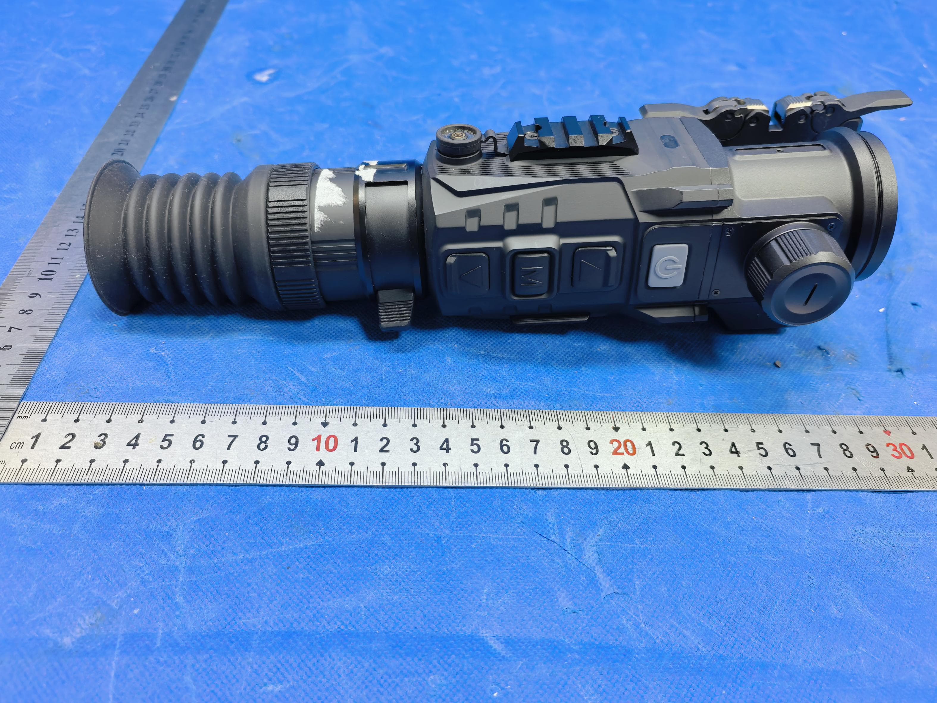
Click to zoom
Application Details
- Equipment Class
- DSS - Part 15 Spread Spectrum Transmitter
- Date of Grant
- Apr 28, 2026
- Application Purpose
- Original Equipment
- Equipment Note
- RICO 3 Thermal Imaging Sight
- Frequency Range
- 2402.00000000 - 2480.00000000
- Country
- China
Documents & Files
Document Text
Text extracted from the exhibit documents filed with the FCC. Open a document above to read the original.
Users Manual
RICO 3 Manual 1. Button Layout and Functions Resolution: 1280×1280, with an inscribed circular UI (similar to ACE. RICO3 is a new brand, UI style must differ from Nocpix). Button Device Status / Current Mode Short Press Long Press Power Button Off --- Power on Main interface Shutter calibration Power off (3s shutdown countdown) Continuous ranging Exit ranging mode Menu interface Return to main interface Up / Ranging Button Main interface Single ranging When continuous ranging is on: Open/exit continuous ranging When off: Long press and release triggers single ranging Single ranging Single ranging Same as above Continuous ranging --- Turn off ranging Menu interface Scroll up menu options --- Menu / M Button Main interface Enter quick menu Enter advanced menu Quick menu Adjust specific function parameters Save and return to previous menu Advanced menu Toggle on/off / Enter submenu / Confirm parameter Down / Photo Button Main interface Take photo Start video recording Recording interface Take photo End and save video Menu interface Scroll down menu options --- Button Device Status / Current Mode Short Press Long Press Rotary Encoder Main interface Rotate to adjust digital zoom (left: zoom out, right: zoom in) Up + Down Main interface Background calibration Background calibration Power + Up Main interface Standby / Wake --- 2. Hold down the power button 1. Power on: When the device is off, press and hold the power button. 2. Power Off: While the device is powered on, press and hold the power button until the logo appears on the screen, then release the button. The 3-2-1 countdown (with 0.7-second intervals) will then complete, shutting down the device. Before the countdown ends, press any key briefly to cancel the shutdown (the shutdown interface displays: "Any key cancels shutdown"). After shutting down, power on the device again; the magnification setting must match that of the rotary encoder, transitioning from 1x electronic zoom to the actual magnification level. 3. Short press the up button – initiate a single ranging measurement Single-range measurement: The SGL icon and range value are displayed at the upper two-thirds of the interface (single-range measurement). The measurement duration is configured in the Advanced Menu> Laser Range Measurement> Range Data (2 seconds / non-fading). A range indication icon appears in the center of the screen; when the range exceeds the measurable distance, the message "----yd" is displayed. Single-range measurements require immediate feedback. 4. Hold down the Up key – perform a single ranging measurement or continuous ranging measurement The long press function for range measurement can be configured in the Advanced Menu> Laser Range Measurement> Continuous LRF. When the Continuous LRF function is enabled, holding the range measurement button activates continuous ranging. The CONT icon and range value update in real-time at approximately two-thirds of the interface. Reholding the button turns off the function, causing both the icon and range display to disappear. When the Continuous LRF function is disabled, holding the range measurement button still activates the single- range measurement function; releasing the button triggers range measurement, displaying the SGL icon and range value at approximately two-thirds of the interface. The display timing matches that of Advanced Menu> Laser Range Measurement> RangeData. 5. Short press the Menu M key to open the shortcut menu; use the ↑ and ↓ keys to switch between menu options. Short-pressing the M key adjusts specific menu parameters, with settings cycling continuously. Long-press the M key saves changes and returns to the main interface; if no action is taken within 10 seconds, the current changes will be automatically saved and you'll return to the main interface. 6. Long press the M key to access the Advanced Menu. Short press the M key to switch between on/off, navigate to the next level of the Advanced Menu, confirm option parameters (selected items will flash briefly), and return directly to the previous level. Short press the power button to exit without saving and return to the main interface. Long press the M key to save changes and return to the previous menu level; if no action is performed within 10 seconds, the current changes will not be saved and you will return to the main interface. Previously selected menu items will be saved (in the main menu's first-level interface, no action triggers automatic exit; in the main menu's second-level or deeper menus, no automatic exit occurs). 7. Press the shutter button briefly to take a photo. On the home screen, the camera icon flashes briefly indicating the photo is taken. When memory is nearly full, a "!" prompt appears. 8. Long press the record button to start recording. The camera icon will disappear on the main screen, and the recording time will be displayed. Short press the camera button; the camera icon will flash, indicating that a photo has been taken. Long press the ↓ button to exit recording mode and save the video. 9. Zoom lever (standard model) ------Zoom: On the main interface, rotate the zoom lever from left to right to electronically adjust the magnification (4x for model 384,8x for model 640), with the magnification displayed in the information interface accordingly. Zoom lever (Pro model) ------Zoom: On the main interface, rotate the zoom lever from left to right to achieve hybrid optical and digital zoom. The magnification scale on the information interface changes accordingly; the UI shrinks proportionally with the optical magnification, ensuring full display of the information interface within the eyepiece (the UI alone must adjust continuously and seamlessly in real time). 1、Constant Display Interface Display the time in the middle of the upper arc on the top status bar The items below are listed in order: 1. visual amplification 2. Image frame rate: 60Hz/90Hz switching () Pro model 3. High Definition Mode Switch 4. Manual/Au…
Text truncated - open the document above for the full version.
External Photos
ReportNo.:AGC10839260101AP02 Page 1 of 3 EXTERNALPHOTOS TOPVIEWOFEUT BOTTOMVIEWOFEUT ReportNo.:AGC10839260101AP02 Page 2 of 3 FRONTVIEWOFEUT BACKVIEWOFEUT ReportNo.:AGC10839260101AP02 Page 3 of 3 LEFTVIEWOFEUT RIGHTVIEWOFEUT ****************************************EndofReport*************************************
ID Label/Location Info
Label Location
RF Exposure Info
Page1of59 SARTestReport ReportNo.:AGC10839260101FH01 FCCID: 2BHFB-RICO3-00 APPLICATIONPURPOSE: OriginalEquipment PRODUCTDESIGNATION: RICO3ThermalImagingSight BRANDNAME: N/A MODELNAME: H50R,H35R,L35R APPLICANT: InlumenTechnologiesCo.,Ltd. DATEOFISSUE: Apr.20,2026 STANDARD(S): IEEEStd.1528:2013 FCC47CFRPart2§2.1093 IEEEStdC95.1™-2019 REPORTVERSION: V1.0 AttestationofGlobalCompliance(Shenzhen)Co.,Ltd. ReportNo.:AGC10839260101FH01 Page 2 of 59 ReportReviseRecord ReportVersionReviseTimeIssuedDateValidVersionNotes V1.0/Apr.20,2026ValidInitialRelease ReportNo.:AGC10839260101FH01 Page 3 of 59 TestReport ApplicantNameInlumenTechnologiesCo.,Ltd. ApplicantAddress Room806,A1,Phase3,lnnovationIndustrialPark,High-techZone,HefeiCity, AnhuiProvince,China. ManufacturerNameInlumenTechnologiesCo.,Ltd. ManufacturerAddress Room806,A1,Phase3,lnnovationIndustrialPark,High-techZone,HefeiCity, AnhuiProvince,China. FactoryNameInlumenTechnologiesCo.,Ltd. FactoryAddress Room806,A1,Phase3,lnnovationIndustrialPark,High-techZone,HefeiCity, AnhuiProvince,China. ProductDesignationRICO3ThermalImagingSight BrandNameN/A ModelNameH50R SeriesModelsH35R,L35R DifferentDescriptionAllthesame,exceptforthemodelnameanddetector EUTVoltageDC2.8~5VbybatteryorDC5Vbyadapter ApplicableStandard IEEEStd.1528:2013 FCC47CFRPart2§2.1093 IEEEStdC95.1™-2019 Dateofreceiptoftestitem Jan.26,2026 TestDateApr.01,2026toApr.07,2026 ReportTemplateAGCRT-US-5G/SAR(2021-04-20) Note:Theresultsoftestinginthisreportapplytotheproduct/systemwhichwastestedonly. PreparedBy TheaHuang(ProjectEngineer)Apr.20,2026 ReviewedBy JackGui(Reviewer)Apr.20,2026 ApprovedBy AngelaLi(AuthorizedOfficer)Apr.20,2026 ReportNo.:AGC10839260101FH01 Page 4 of 59 TABLEOFCONTENTS 1.SUMMARYOFMAXIMUMSARVALUE...........................................................................................................5 2.GENERALINFORMATION................................................................................................................................6 2.1.EUTDESCRIPTION..........................................................................................................................................6 3.SARMEASUREMENTSYSTEM.........................................................................................................................7 3.1.THESATIMOSYSTEMUSEDFORPERFORMINGCOMPLIANCETESTSCONSISTSOFFOLLOWINGITEMS..................7 3.2.COMOSARE-FIELDPROBE...........................................................................................................................8 3.3.ROBOT...........................................................................................................................................................8 3.4.VIDEOPOSITIONINGSYSTEM...........................................................................................................................9 3.5.DEVICEHOLDER..............................................................................................................................................9 3.6.SAMTWINPHANTOM....................................................................................................................................10 4.SARMEASUREMENTPROCEDURE...............................................................................................................11 4.1.SPECIFICABSORPTIONRATE(SAR)...............................................................................................................11 4.2.SARMEASUREMENTPROCEDURE.................................................................................................................12 4.3.RFEXPOSURECONDITIONS..........................................................................................................................14 5.TISSUESIMULATINGLIQUID..........................................................................................................................16 5.1.THECOMPOSITIONOFTHETISSUESIMULATINGLIQUID.....................................................................................16 5.2.TISSUEDIELECTRICPARAMETERSFORHEADANDBODYPHANTOMS...............................................................16 5.3.TISSUECALIBRATIONRESULT.........................................................................................................................17 6.SARSYSTEMCHECKPROCEDURE.............................................................................................................18 6.1.SARSYSTEMCHECKPROCEDURES..............................................................................................................18 6.2.SARSYSTEMCHECK....................................................................................................................................19 7.EUTTESTPOSITION.......................................................................................................................................21 7.1.BODYWORNPOSITION..................................................................................................................................21 8.SAREXPOSURELIMITS.................................................................................................................................22 9.TESTFACILITY................................................................................................................................................23 10.TESTEQUIPMENTLIST................................................................................................................................24 11.MEASUREMENTUNCERTAINTY..................................................................................................................25 12.CONDUCTEDPOWERMEASUREMENT......................................................................................................28 13.TESTRESULTS.............................................................................................................................................31 13.1.SARTESTRESULTSSUMMARY.........................................…
Text truncated - open the document above for the full version.
Test Report
Product OC: Y0RBW0CA1AA Version: 1.0 Date: 2026-04-01 Product Name: WIFI FPC Antenna Key Features: Frequency Band: 2400~2500 MHz、5150~5850 MHz dimension: 29.3 mm × 13.3 mm Efficiency: Up to 65 % RoHS Compliant Antenna Datasheet 天线服务 Y0RBW0CA1AA规格书 天线规格书 1 / 13 目录 目录 .............................................................................................................................................................. 1 1 Specification ........................................................................................................................................ 2 1.1. Electrical ..................................................................................................................................... 2 1.2. Mechanical & Environmental ..................................................................................................... 2 1.3. Matching Circuit ......................................................................................................................... 3 2 Drawing ................................................................................................................................................ 4 3 Detailed Performance ......................................................................................................................... 5 3.1. S-Parameter Test ....................................................................................................................... 5 3.1.1. VSWR ............................................................................................................................ 5 3.2. Radiation Performance Test ....................................................................................................... 6 3.2.1. Efficiency ........................................................................................................................ 6 3.2.2. Peak Gain ...................................................................................................................... 7 4 Packaging ............................................................................................................................................ 8 联系我们 ..................................................................................................................................................... 10 法律声明 ..................................................................................................................................................... 11 文档历史 ..................................................................................................................................................... 13 天线服务 Y0RBW0CA1AA规格书 天线规格书 2 / 13 1 Specification Test Condition:整机测试 1.1. Electrical 1.2. Mechanical & Environmental Electrical Frequency Range 2400~2500 MHz、5150~5850 MHz Impedance 50 Ω Polarization 线极化 Radiation Pattern 全向 VSWR ≤ 2.3 Peak Gain 2400~2500 MHz 2.5 dBi 5150~5850 MHz 3.3 dBi Mechanical Antenna Dimensions 29.3 mm × 13.3 mm Material & color FPC & Black cable & color & length RF1.13&Black&65mm connector IPEX MHF 1 Weight Typ. 0.42 g Mounting Type Adhesive 天线服务 Y0RBW0CA1AA规格书 天线规格书 3 / 13 1.3. Matching Circuit Environmental Operation Temperature -40 °C ~ +85 °C Storage Temperature -40 °C ~ +85 °C RoHS Compliant Yes E1 E2 E3 E4 Default Matching NC NC 0 Ω NC Tolerance N/A N/A N/A N/A Wireless Module E1 E2 E3 E4 Antenna 天线服务 Y0RBW0CA1AA规格书 天线规格书 4 / 13 2 Drawing 天线服务 Y0RBW0CA1AA规格书 天线规格书 5 / 13 3 Detailed Performance 3.1. S-Parameter Test 3.1.1. VSWR 1 2 3 4 5 6 7 8 9 10 20002100220023002400250026002700280029003000310032003300340035003600370038003900400041004200430044004500460047004800490050005100520053005400550056005700580059006000 VSWR Frequency(MHz) VSWR VSWR Frequency (MHz) 2400 2450 2500 5150 5500 5850 5925 6525 7125 VSWR 2.0 1.9 1.8 2.3 1.4 1.8 - - - 天线服务 Y0RBW0CA1AA规格书 天线规格书 6 / 13 3.2. Radiation Performance Test 3.2.1. Efficiency 0 10 20 30 40 50 60 70 80 90 100 20002100220023002400250026002700280029003000310032003300340035003600370038003900400041004200430044004500460047004800490050005100520053005400550056005700580059006000 Efficiency(%) Frequency(MHz) Efficiency Efficiency (%) Frequency (MHz) 2400 2450 2500 5150 5500 5850 5925 6525 7125 Efficiency (%) 32.8 36.0 33.7 48.1 64.2 56.1 - - - 天线服务 Y0RBW0CA1AA规格书 天线规格书 7 / 13 3.2.2. Peak Gain -5 -3 -1 1 3 5 20002100220023002400250026002700280029003000310032003300340035003600370038003900400041004200430044004500460047004800490050005100520053005400550056005700580059006000 Peak Gain(dBi) Frequency(MHz) Peak Gain 峰值增益(dBi) Frequency (MHz) 2400 2450 2500 5150 5500 5850 5925 6525 7125 Peak Gain (dBi) 1.5 2.5 1.6 1.5 3.1 2.7 - - - 天线服务 Y0RBW0CA1AA规格书 天线规格书 8 / 13 4 Packaging 步骤 包装图片 / 2D图片 简述 1 20个产品一扎,端子头用珍珠棉包裹好 2 一个PE袋装5扎 一个PE袋装100个产品 3 一个吸塑盒装2个PE袋 一个吸塑盒装200个产品。 4 一箱装10个吸塑盒。 一箱装2000个产品。 预估数量 不满箱的产品将用合适的纸箱包装。 外箱尺寸:405 × 293 × 185 mm 天线服务 Y0RBW0CA1AA规格书 天线规格书 9 / 13 5 标签位置 ① 纸箱标签 ② 质量标签 6 纸箱密封 “工”字形封箱 备注 上述初始包装方式仅供参考,最终实际包装方式以实际出货包装为准。 天线服务 Y0RBW0CA1AA规格书 天线规格书 10 / 13 联系我们 上海移远通信技术股份有限公司(以下简称“移远通信”)始终以为客户提供最及时、最全面的服务为宗旨。 如需任何帮助,请随时联系我司上海总部,联系方式如下: 上海移远通信技术股份有限公司 上海市松江区泗泾镇外婆泾路8号 邮编:201601 电话:+86 21 5108 6236 邮箱:[email protected] 或联系我司当地办事处,详情请登录:https://www.quectel.com.cn/contact。 如需技术支持或反馈我司技术文档中的问题,请随时登录网址: https://www.quectel.com.cn/contact?tab=t 或发送邮件至:[email protected]。 天线服务 Y0RBW0CA1AA规格书 天线规格书 11 / 13 法律声明 移远通信提供该文档内容以支持您的产品设计。您须按照文档中提供的规范、参数来设计产品。同时,您理 解并同意,移远通信提供的参考设计仅作为示例。您同意在设计您目标产品时使用您独立的分析、评估和判 断。在使用本文档所指导的任何硬软件或服务之前,请仔细阅读本声明。您在此承认并同意,尽管移远通信 采取了商业范围内的合理努力来提供尽可能好的体验,但本文档和其所涉及服务是在“可用”基础上提供给 您的。您知悉并同意,移远通信可在未事先通知的情况下,自行决定随时增加、修改或重述本文档,增加、 修改或重述后的文档对您具有约束力。 使用和披露限制 许可协议 除非移远通信特别授权,否则我司所提供硬软件、材料和文档的接收方须对接收的内容保密,不得将其用于 除本项目的实施与开展以外的任何其他目的。 版权声明 移远通信产品和本协议项下的第三方产品可能包含受移远通信或第三方材料、硬软件和文档版权保护的相 关资料。除非事先得到书面同意,否则您不得获取、使用、向第三方披露我司所提供的文档和信息,或对此 类受版权保护的资料进行复制、转载、抄袭、出版、展示、翻译、分发、合并、修改,或创造其衍生作品。 移远通信或第三方对受版权保护的资料拥有专有权,不授予或转让任何专利、版权、商标或服务商标权的许 可。为避免歧义,任何形式的购买都不可被视为授予除正常的非独家、免版税的产品使用许可之外的任何许 可。对于任何违反保密义务、未经授权使用或以其他非法形式恶意使用所述文档和信息的违法、侵权行为, 移远通信…
Text truncated - open the document above for the full version.
Test Report
Page 1 of 79 FCCTestReport ReportNo.:AGC10839260101FR01 FCCID:2BHFB-RICO3-00 APPLICATIONPURPOSE:OriginalEquipment PRODUCTDESIGNATION:RICO3ThermalImagingSight BRANDNAME:N/A MODELNAME:RICO3H50R,RICO3H35R,RICO3L35R APPLICANT:InlumenTechnologiesCo.,Ltd. DATEOFISSUE:Apr.20,2026 STANDARD(S):FCCPart15SubpartC§15.247 REPORTVERSION:V1.0 AttestationofGlobalCompliance(Shenzhen)Co.,Ltd ReportNo.:AGC10839260101FR01 Page2of79 ReportReviseRecord ReportVersionReviseTimeIssuedDateValidVersionNotes V1.0/Apr.20,2026ValidInitialRelease ReportNo.:AGC10839260101FR01 Page3of79 TableofContents 1.GeneralInformation..........................................................................................................................................5 2.ProductInformation..........................................................................................................................................6 2.1ProductTechnicalDescription....................................................................................................................6 2.2TestFrequencyList.....................................................................................................................................6 2.3RelatedSubmittal(S)/Grant(S).................................................................................................................7 2.4TestMethodology........................................................................................................................................7 2.5ReceiverInputBandwidth...........................................................................................................................7 2.6EquallyAverageUseofFrequenciesandBehaviour................................................................................7 2.7PseudorandomFrequencyHoppingSequence.........................................................................................8 2.8SpecialAccessories....................................................................................................................................9 2.9EquipmentModifications.............................................................................................................................9 2.10AntennaRequirement...............................................................................................................................9 3.TestEnvironment............................................................................................................................................10 3.1AddressofTheTestLaboratory................................................................................................................10 3.2TestFacility................................................................................................................................................10 3.3EnvironmentalConditions.........................................................................................................................11 3.4MeasurementUncertainty.........................................................................................................................11 3.5ListofEquipmentUsed.............................................................................................................................12 4.SystemTestConfiguration............................................................................................................................14 4.1EUTConfiguration....................................................................................................................................14 4.2EUTExercise............................................................................................................................................14 4.3ConfigurationofTestedSystem................................................................................................................14 4.4EquipmentUsedinTestedSystem..........................................................................................................15 4.5SummaryofTestResults..........................................................................................................................16 5.DescriptionofTestModes.............................................................................................................................17 6.RFOutputPowerMeasurement....................................................................................................................18 6.1ProvisionsApplicable................................................................................................................................18 6.2MeasurementProcedure..........................................................................................................................18 6.3MeasurementSetup(BlockDiagramofConfiguration)...........................................................................18 6.4MeasurementResult.................................................................................................................................19 7.20dBBandwidthand99%OccupiedBandwidthMeasurement...............................................................25 7.1ProvisionsApplicable................................................................................................................................25 7.2MeasurementProcedure..........................................................................................................................25 7.3MeasurementSetup(BlockDiagramofConfiguration)...........................................................................25 7.4MeasurementResults...............................................................................................................................26 8.ConductedBandEdgeandOut-of-BandEmissions..................................................................................31 8.1ProvisionsApplicable......................................................................................................…
Text truncated - open the document above for the full version.
Test Report
ReportNo.:AGC10839260101FR01 Page43of79 Test_Graph_EDR_ANT1_2402_3Mbps_HigherBandEmissions Test_Graph_EDR_ANT1_2441_3Mbps_ReferenceLevel ReportNo.:AGC10839260101FR01 Page44of79 Test_Graph_EDR_ANT1_2441_3Mbps_LowerBandEmissions Test_Graph_EDR_ANT1_2441_3Mbps_HigherBandEmissions ReportNo.:AGC10839260101FR01 Page45of79 Test_Graph_EDR_ANT1_2480_3Mbps_ReferenceLevel Test_Graph_EDR_ANT1_2480_3Mbps_LowerBandEmissions ReportNo.:AGC10839260101FR01 Page46of79 Test_Graph_EDR_ANT1_2480_3Mbps_HigherBandEmissions ReportNo.:AGC10839260101FR01 Page47of79 TestGraphsofBandEdgeEmissionsinNon-RestrictedFrequencyBands Test_Graph_BR_ANT1_2402_1Mbps_LowerBandEdgeEmissions Test_Graph_BR_ANT1_2480_1Mbps_HigherBandEdgeEmissions ReportNo.:AGC10839260101FR01 Page48of79 Test_Graph_BR_HOP_ANT1_NA_1Mbps_LowerBandEdgeEmissions Test_Graph_BR_HOP_ANT1_NA_1Mbps_HigherBandEdgeEmissions ReportNo.:AGC10839260101FR01 Page49of79 Test_Graph_EDR_ANT1_2402_2Mbps_LowerBandEdgeEmissions Test_Graph_EDR_ANT1_2480_2Mbps_HigherBandEdgeEmissions ReportNo.:AGC10839260101FR01 Page50of79 Test_Graph_EDR_HOP_ANT1_NA_2Mbps_LowerBandEdgeEmissions Test_Graph_EDR_HOP_ANT1_NA_2Mbps_HigherBandEdgeEmissions ReportNo.:AGC10839260101FR01 Page51of79 Test_Graph_EDR_ANT1_2402_3Mbps_LowerBandEdgeEmissions Test_Graph_EDR_ANT1_2480_3Mbps_HigherBandEdgeEmissions ReportNo.:AGC10839260101FR01 Page52of79 Test_Graph_EDR_HOP_ANT1_NA_3Mbps_LowerBandEdgeEmissions Test_Graph_EDR_HOP_ANT1_NA_3Mbps_HigherBandEdgeEmissions ReportNo.:AGC10839260101FR01 Page53of79 9.RadiatedSpuriousEmission 9.1MeasurementLimit 15.209Limitinthebelowtablehastobefollowed Frequencies (MHz) FieldStrength (microvolts/meter) MeasurementDistance (meters) 0.009~0.4902400/F(kHz)300 0.490~1.70524000/F(kHz)30 1.705~30.03030 30~881003 88~2161503 216~9602003 Above9605003 Note:Allmodesweretestedforrestrictedbandradiatedemission,thetestrecordsreportedbelowaretheworst resultcomparedtoothermodes. 9.2MeasurementProcedure 1.TheEUTwasplacedonthetopoftheturntable0.8or1.5meteraboveground.Thephasecenterofthe receivingantennamountedonthetopofaheight-variableantennatowerwasplaced3metersfaraway fromtheturntable. 2.PowerontheEUTandallthesupportingunits.Theturntablewasrotatedby360degreestodeterminethe positionofthehighestradiation. 3.Theheightofthebroadbandreceivingantennawasvariedbetweenonemeterandfourmetersabove groundtofindthemaximumemissionsfieldstrengthofbothhorizontalandverticalpolarization. 4.Foreachsuspectedemission,theantennatowerwasscan(from1Mto4M)andthentheturntablewas rotated(from0degreeto360degrees)tofindthemaximumreading. 5.Setthetest-receiversystemtoPeakorCISPRquasi-peakDetectFunctionwithspecifiedbandwidthunder MaximumHoldMode. 6.Foremissionsabove1GHz,insertthe2.4GfilterbetweenthereceivingantennaandthePre-amplifier(only forRadiatedSpuriousEmission).Use1MHzRBWand3MHzVBWforpeakreading.Placethe measurementantennaawayfromeachareaoftheEUTdeterminedtobeasourceofemissionsatthe specifiedmeasurementdistance,whilekeepingthemeasurementantennaaimedatthesourceof emissionsateachfrequencyofsignificantemissions,withpolarizationorientedformaximumresponse. ThemeasurementantennamayhavetobehigherorlowerthantheEUT,dependingontheradiation patternoftheemissionandstayingaimedattheemissionsourceforreceivingthemaximumsignal.The finalmeasurementantennaelevationshallbethatwhichmaximizestheemissions.Themeasurement antennaelevationformaximumemissionsshallberestrictedtoarangeofheightsoffrom1mto4m abovethegroundorreferencegroundplane. ReportNo.:AGC10839260101FR01 Page54of79 7.Whentheradiatedemissionslimitsareexpressedintermsoftheaveragevalueoftheemissions,and pulsedoperationisemployed,themeasurementfieldstrengthshallbedeterminedbyaveragingoverone completepulsetrain,includingblankingintervals,aslongasthepulsetraindoesnotexceed0.1seconds. Asanalternative(providedthetransmitteroperatesforlongerthan0.1seconds)orincaseswherethe pulsetrainexceeds0.1seconds,themeasuredfieldstrengthshallbedeterminedfromtheaverage absolutevoltageduringa0.1secondintervalduringwhichthefieldstrengthisatitsmaximumvalues. 8.IftheemissionsleveloftheEUTinpeakmodewas3dBlowerthantheaveragelimitspecified,then testingwillbestoppedandpeakvaluesofEUTwillbereported,otherwise,theemissionswhichdonot have3dBmarginwillberepeatedonebyoneusingthequasi-peakmethodforbelow1GHz. 9.Fortestingabove1GHz,theemissionsleveloftheEUTinpeakmodewaslowerthanaveragelimit(that meanstheemissionslevelinpeakmodealsocomplieswiththelimitinaveragemode),thentestingwillbe stoppedandpeakvaluesofEUTwillbereported,otherwise,theemissionswillbemeasuredinaverage modeagainandreported. 10.Incasetheemissionislowerthan30MHz,loopantennahastobeusedformeasurementandtherecorded datashouldbeQPmeasuredbyreceiver.High-Lowscanisnotrequiredinthiscase. Thefollowingtableisthesettingofspectrumanalyzerandreceiver. SpectrumParameterSetting Start~StopFrequency9KHz~150KHz/RB200HzforQP Start~StopFrequency150KHz~30MHz/RB9KHzforQP Start~StopFrequency30MHz~1000MHz/RB120KHzforQP Start~StopFrequency 1GHz~26.5GHz 1MHz/3MHzforPeak,1MHz/3MHzforAverage ReceiverParameterSetting Start~StopFrequency9KHz~150KHz/RB200HzforQP Start~StopFrequency150KHz~30MHz/RB9KHzforQP Start~StopFrequency30MHz~1000MHz/RB120KHzforQP ReportNo.:AGC10839260101FR01 Page55of79 Quasi-PeakMeasurementsbelow1GHz 1.Analyzercenterfrequencywassettothefrequencyoftheradiatedspuriousemissionofinterest 2.Spanwassetgreaterthan1MHz 3.RBW=asshowninthetableabove 4.Detector=CISPRquasi-peak 5.Sweeptime=autocouple 6.Tracewasallowedtostabilize PeakMeasurementsabove1GHz 1.Analyzercenterfrequencywassettothefrequencyoftheradiatedspuriousemissionofinterest 2.RBW=1MHz 3.VBW=3MHz 4.Detector=peak 5.Sweeptime=autocouple 6.Tracemode=maxhold 7.Tracewasallowedtostabiliz…
Text truncated - open the document above for the full version.
Contact Information
Applicant
shirley fu
[email protected]Fax: 400-999-3800
Technical Contact
iRay USA, LLCTyler Adair
2601 State Hwy 121 Building 3 Suite 302 · Lewisville, Texas, 75056 · China
Test Firm
Attestation of Global Compliance (Shenzhen) Co., LDoris Li
Technical Specifications
| # | Rule Parts | Frequency Range | Power Output |
|---|---|---|---|
| 1 | 15C | 2.40 GHz - 2.48 GHz | 2.50 mW |
Other Applications from Inlumen Technologies Co., Ltd.
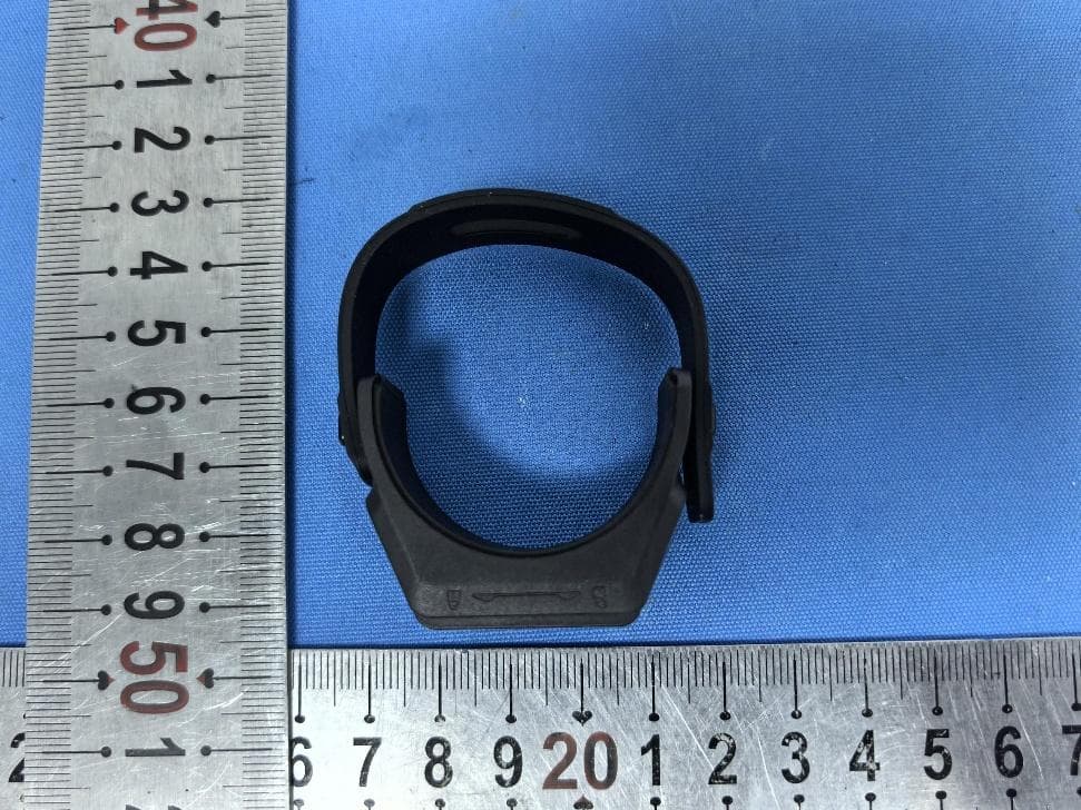
2BHFB-MATE-00
Aug 10, 2026Magic Zoom
Equipment Class
DTS - Digital Transmission System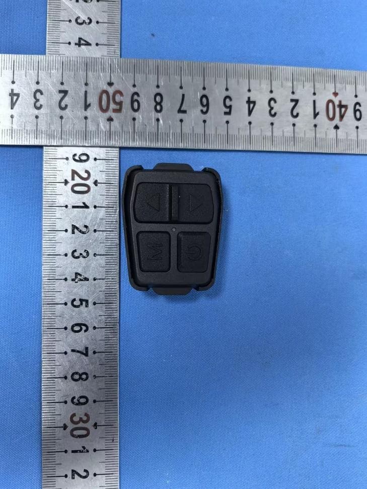
2BHFB-MATE-01
Aug 10, 2026Nocpix Remote Control
Equipment Class
DTS - Digital Transmission System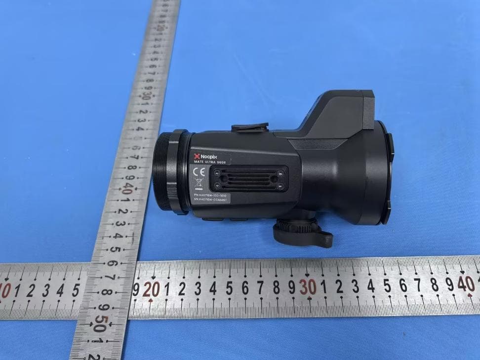
2BHFB-4071-00
Jul 13, 2026Mate Series Thermal Imaging Attachment
Equipment Class
DTS - Digital Transmission System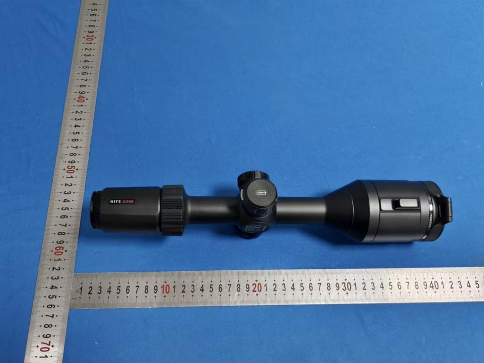
2BHFB-4066-00
Jun 01, 2026Digital Night Vision Scope
Equipment Class
DTS - Digital Transmission System2BHFB-5041-00
May 05, 2026Remote Control
Equipment Class
DTS - Digital Transmission System