A2M-AGA-TC3Hand Held Cooking Control
Aga Rangemaster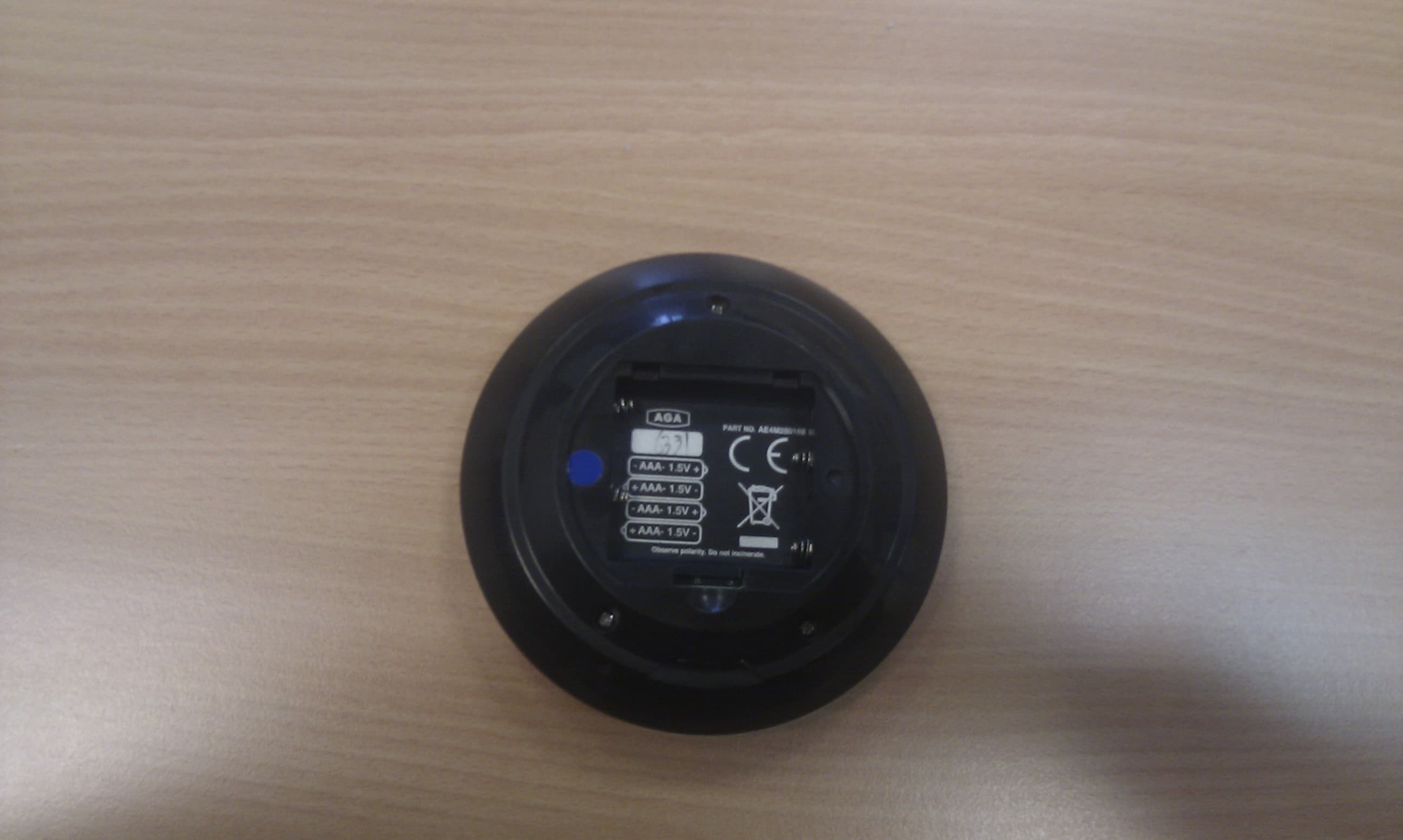
Click to zoom
Application Details
- Equipment Class
- DXX - Part 15 Low Power Communication Device Transmitter
- Date of Grant
- May 03, 2012
- Application Purpose
- Original Equipment
- Date of Application
- May 03, 2012
- Equipment Note
- Hand Held Cooking Control
- Frequency Range
- 914.50000000 - 914.50000000
- Company
- Aga Rangemaster
- Country
- United Kingdom
Documents & Files
Document Text
Text extracted from the exhibit documents filed with the FCC. Open a document above to read the original.
Users Manual
GENERAL NOTES 3 NOTE:THESE INSTALLATION INSTRUCTIONS SHOULD BE LEFT WITH THE APPLIANCE AND THE USER TO RETAIN FOR FUTURE REFERENCE. Before installation of an AGA can be made, the site is inspected for suitability by an authorized AGA distributor and corrected where necessary to conform with local installation codes or in the absence of local codes with: NATIONAL ELECTRICAL CODES ANSI/NFPA 70. DELIVERY REQUIREMENTS There must be access to the kitchen to manipulate a foot print of 39 9 /16” (1005mm) x 29 1 /8” (740mm). A wooden template (skate with castor wheels) of dimensions 39 9 /16” (1005mm) x 29 1 /8” (740mm) could be used to check if the AGA Total Control (TC3) part built appliance is able to fit through the property grounds and doors into its installation position in the kitchen. It must also be considered that the height of the appliance is 35 13 /16” (910mm), so high level obstacles/restrictions must not be overlooked. If this skate/template canbe manipulated through the property grounds and doors into position, then the AGA Total Control (TC3) can be installed as intended with no re-work. If the skate/template cannotbe manipulated through the property grounds and doors, into position then the following must be considered. Use of specialised delivery company who can remove property doors/windows etc to gain greater access or use specialised equipment, such as a stair lifter. GENERAL INSTALLATION REQUIREMENTS The installation of the range must be in accordance with the relevant requirements of the local Wiring and Building Regulations. It should be in accordance also with any relevant requirements of the Local Authority. In your own interest and that of safety to comply with the law, all appliances should be installed by an authorized AGA distributor in accordance with the relevant regulations. USA Model Number FCC ID: A2M-AGA-TC3 FCC ID: A2M-AGA-TC3CKR This device complies with part 15 of the FCC Rules. Operation is subject to the following two conditions: (1) This device may not cause harmful interference, and (2) this device must accept any interference received, including interference that may cause undesired operation. CANADA Model Number IC 10181A-AGATC3 IC 10181A-AGATC3CKR Model No. AGA TC3 Button Operations 1. Communication or ‘Handshake’ button used initially to synchronise the handset to the AGA Total Control. (On day of installation or in case of replacement handset 2. Clock button Opens and closes the date and time settings screen. 3. Left/Back Button Moves back and highlights the previous setting. 4. Plus Button Increases the highlighted setting. 5. Minus Button Decreases the highlighted setting. 6. Right/Forward Button Moves forward and highlights the next setting. 7. Copy Button copies the time program from the current day to the following day in the 7-day event calendar screen. 8. 7-day event Button Opens and closes the 7-day event calendar screen. HANDSET - A HAND HELD CONTROL Screens The handset has 3 main screens. 1. The Information Home screen (main menu) 2. The Date/Time screen 3. The Events Programming screen The display will revert to ‘sleep’ mode after approximately 3 minutes. Simply press the required button to open up any screen. The handset displays the time, date and events. Programming is via eight push buttons. The information is displayed via a back-lit LCD screen. HANDSET ADVICE Operating Distance The handset will only operate in the same room as the cooker and up to a maximum distance of 13 feet (4 metres) from the appliance. If out of recommended operating range, the handset may show ‘Standby’. If this happens move the handset back to within the recommended distance and it should correct itself, see below. Handset to AGA Total Control Signal Check The (Standby) symbol is shown when in the following situations:- 1. In Standby mode 2. If communications fail 3. There is a power cut 4. If the handset is out of range of the AGA Total Control cooker When transferring information from or to the controller always operate the handset in front of the cooker, this gives the strongest signal. If the handset shows Standby, when the cooker is on, press the button firmly for 1 second, this will activate the communication link between the cooker and handset. Communication/Handshake For details on initial Communication/Handshake, see Page 11. Preview Mode If the handset is out of range of the cooker or if the appliance is switched off, Preview only mode is available. Changes cannot be made to the programmed events. The symbol is displayed in the screen and the message ‘Preview only’ is displayed briefly when the events program screen is first entered. When in Preview Mode you can review the days by using the and buttons. The and buttons become inactive and you cannot make any changes. Handset Failure In the unlikely event of handset failure, the appliance would still be operational with the last selected program. The cooker can also be changed to Manual mode from one of the auto modes using the mode button on the control panel. If the handset is damaged or lost, a replacement can be obtained from AGA and re-programmed to suit your appliance. DO NOT PLACE THE HANDSET ON ANY HOT SURFACES. 10 USA Model Number AGA TC3 FCC ID: A2M-AGA-TC3 FCC ID: A2M-AGA-TC3CKR This device complies with part 15 of the FCC Rules. Operation is subject to the following two conditions: (1) This device may not cause harmful interference, and (2) this device must accept any interference received, including interference that may cause undesired operation. CANADA Model Number AGA TC3 IC 10181A-AGATC3 IC 10181A-AGATC3CKR Users Instruction 01/12 EOPI 516292 PLEASE READ THESE INSTRUCTIONS BEFORE USING THIS APPLIANCE IMPORTANT : SAVE INSTRUCTIONS FOR THE LOCAL INSPECTORS USE CUSTOMER: KEEP THESE INSTRUCTIONS FOR FUTURE REFERENCE REMEMBER: when replacing a part on this appliance, use only spare parts that you can be assured conform to the safety and performance specification that we require. Do not …
Text truncated - open the document above for the full version.
Test Report
Report No.: 11055686LHD-001b Page: 2 of 63 Product: Total Control Handset controller Issue Date: 17 th April 2012 Model No.: A2M-AGA-TC3 Issue No.: 1 Contents Page No. 1. JOB DESCRIPTION................................................................................................... 4 2. TEST SUMMARY....................................................................................................... 6 2.1. AGA Total Control Controller............................................................................ 6 3. EQUIPMENT UNDER TEST (EUT)......................................................................... 7 3.1. Description of the EUT....................................................................................... 7 3.2. EUT’s Modes of Operation................................................................................ 7 3.3. EUT Configuration Diagram.............................................................................. 7 3.4. EUT Support Equipment.................................................................................... 7 3.5. Cables Associated With the EUT..................................................................... 7 4. TESTS.......................................................................................................................... 8 4.1. Transmitter Output Power (Conducted).......................................................... 8 4.2. Radiated Peak Powers: CFR47 Part 15:249.a.............................................. 8 5. Radiated Emissions – CFR 47 PART15:209........................................................ 13 5.1. Radiated Emissions Test Method.................................................................. 13 5.2. Radiated Emissions Test Results................................................................... 13 5.3. Radiated Emissions Conclusions................................................................... 13 5.4. Measurement Uncertainty............................................................................... 13 6. Photographs of test setup........................................................................................ 59 7. TEST EQUIPMENT.................................................................................................. 61 ANNEX A - REGISTRATION SITES................................................................... 62 Report No.: 11055686LHD-001b Page: 3 of 63 Product: Total Control Handset controller Issue Date: 17 th April 2012 Model No.: A2M-AGA-TC3 Issue No.: 1 TABLES Table 1 Radiated Emissions Test Results – TX Mode - 30-1000MHz Vertical Polarisation.................................................................................................................. 9 Table 2 Radiated Emissions Test Results – TX Mode - 30-1000MHz Horizontal Polarisation................................................................................................................ 11 Table 3 Radiated Emissions Test Results – TX Mode - 30-1000MHz Vertical Polarisation................................................................................................................ 14 Table 4 Radiated Emissions Test Results – TX Mode - 30-1000MHz Horizontal Polarisation................................................................................................................ 16 Table 5 Radiated Emissions Test Results – Standby Mode - 30-1000MHz Vertical Polarisation................................................................................................................ 18 Table 6 Radiated Emissions Test Results – Standby Mode - 30-1000MHz Horizontal Polarisation............................................................................................. 20 Table 7 Radiated Emissions Test Results – TX Mode - 1 - 10GHz Vertical & Horizontal Polarisations........................................................................................... 22 Table 8 Radiated Emissions Test Results – Standby Mode - 1 - 10GHz Vertical & Horizontal................................................................................................................... 43 GRAPHS Graph 1 Radiated Emissions Test Results – TX Mode - 30-1000MHz - Vertical... 10 Graph 2 Radiated Emissions Test Results – TX Mode - 30-1000MHz - Horizontal12 Graph 3 Radiated Emissions Test Results – TX Mode - 30-1000MHz Vertical..... 15 Graph 4 Radiated Emissions Test Results – TX Mode - 30-1000MHz - Horizontal17 Graph 5 Radiated Emissions Test Results – Standby Mode - 30-1000MHz Vertical........................................................................................................................ 19 Graph 6 Radiated Emissions Test Results – Standby Mode - 30-1000MHz Horizontal................................................................................................................... 21 Graph 7 Radiated Emissions Test Results – TX Mode - 1 - 2GHz Vertical – Peak23 Graph 8 Radiated Emissions Test Results – TX Mode - 1 - 2GHz Vertical – Average...................................................................................................................... 24 Graph 9 Radiated Emissions Test Results – TX Mode - 1 - 2GHz Horizontal – Peak............................................................................................................................ 25 Graph 10 Radiated Emissions Test Results – TX Mode - 1 - 2GHz Horizontal – Average...................................................................................................................... 26 Graph 11 Radiated Emissions Test Results – TX Mode - 2 - 4GHz Vertical – Peak27 Graph 12 Radiated Emissions Test Results – TX Mode - 2 - 4GHz Vertical – Average...................................................................................................................... 28 Graph 13 Radiated Emissions Test Results – TX Mode - 2 - 4GHz Horizontal – Peak...........................................................................................…
Text truncated - open the document above for the full version.
Contact Information
Applicant
David Ian Carpenter(Mr)
Test Firm
IntertekDavid Feasey
Technical Specifications
| # | Rule Parts | Frequency Range | Power Output |
|---|---|---|---|
| 1 | 15C | 914.5 MHz - 914.5 MHz | - |
Other Applications from Aga Rangemaster
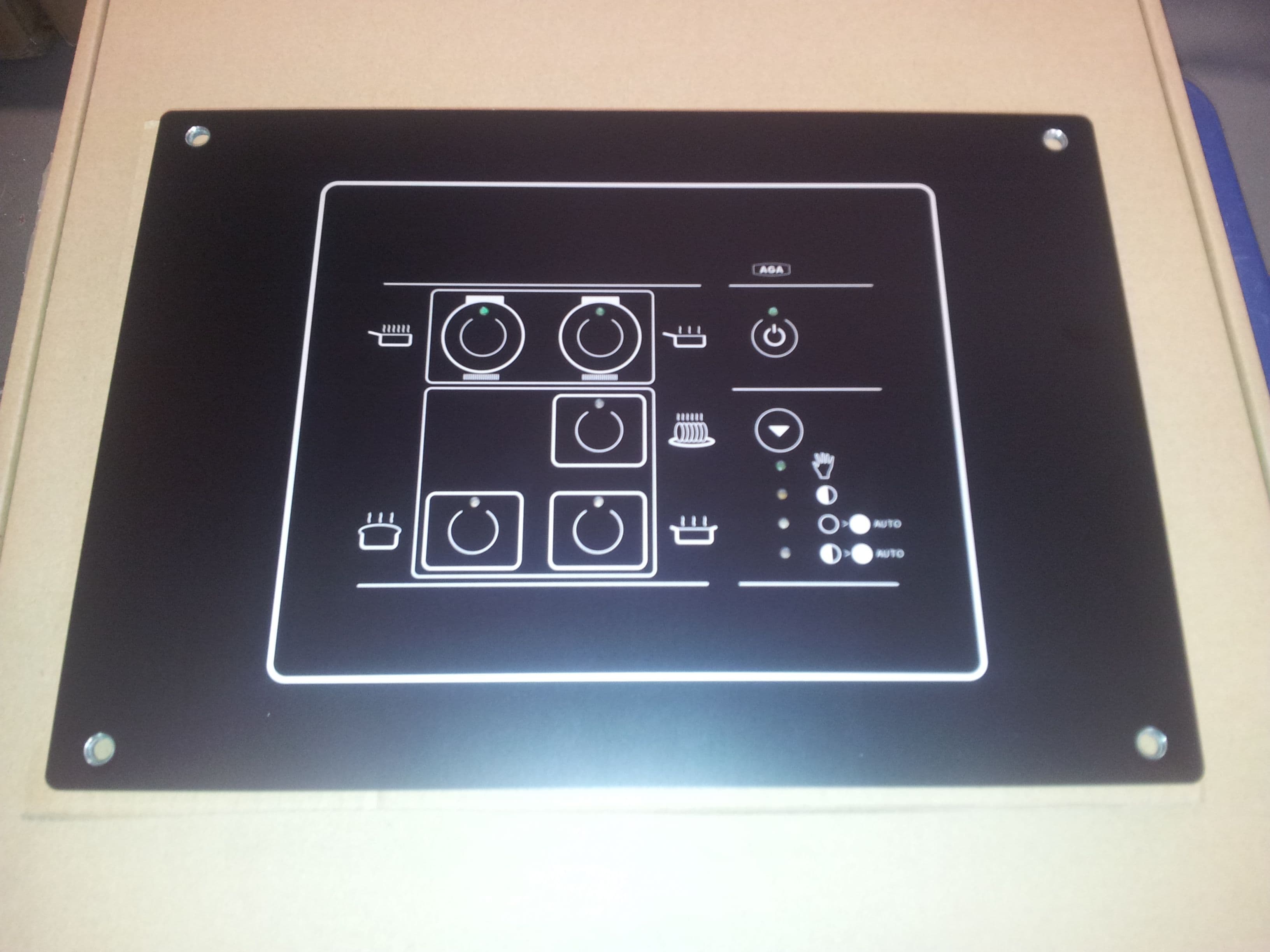
A2M-AGA-TC3TEK
Jul 02, 2014Low Powered Communication Device Fitted Into a Range Cooker
Equipment Class
DXT - Part 15 Low Power Transceiver, Rx Verified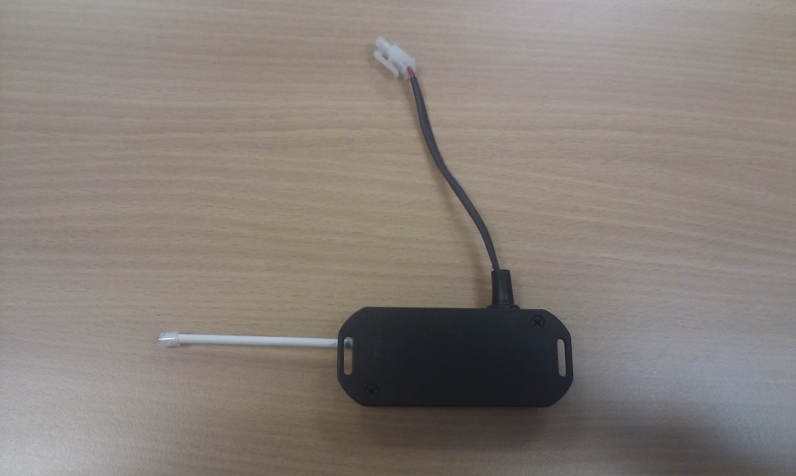
A2M-AGA-TC3CKR
May 03, 2012Electric Cooker
Equipment Class
DXX - Part 15 Low Power Communication Device Transmitter