A2M-AGA-TC3CKRElectric Cooker
Aga Rangemaster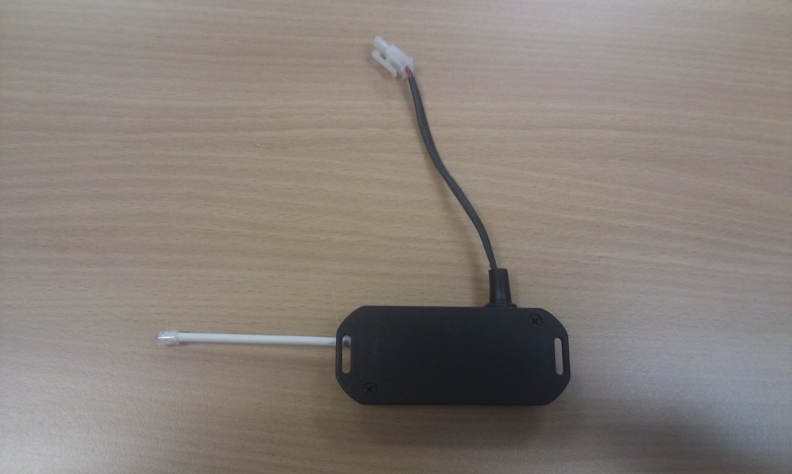
Click to zoom
Application Details
- Equipment Class
- DXX - Part 15 Low Power Communication Device Transmitter
- Date of Grant
- May 03, 2012
- Application Purpose
- Original Equipment
- Date of Application
- May 03, 2012
- Equipment Note
- Electric Cooker
- Frequency Range
- 914.50000000 - 914.50000000
- Company
- Aga Rangemaster
- Country
- United Kingdom
Documents & Files
Document Text
Text extracted from the exhibit documents filed with the FCC. Open a document above to read the original.
Users Manual
GENERAL NOTES 3 NOTE:THESE INSTALLATION INSTRUCTIONS SHOULD BE LEFT WITH THE APPLIANCE AND THE USER TO RETAIN FOR FUTURE REFERENCE. Before installation of an AGA can be made, the site is inspected for suitability by an authorized AGA distributor and corrected where necessary to conform with local installation codes or in the absence of local codes with: NATIONAL ELECTRICAL CODES ANSI/NFPA 70. DELIVERY REQUIREMENTS There must be access to the kitchen to manipulate a foot print of 39 9 /16” (1005mm) x 29 1 /8” (740mm). A wooden template (skate with castor wheels) of dimensions 39 9 /16” (1005mm) x 29 1 /8” (740mm) could be used to check if the AGA Total Control (TC3) part built appliance is able to fit through the property grounds and doors into its installation position in the kitchen. It must also be considered that the height of the appliance is 35 13 /16” (910mm), so high level obstacles/restrictions must not be overlooked. If this skate/template canbe manipulated through the property grounds and doors into position, then the AGA Total Control (TC3) can be installed as intended with no re-work. If the skate/template cannotbe manipulated through the property grounds and doors, into position then the following must be considered. Use of specialised delivery company who can remove property doors/windows etc to gain greater access or use specialised equipment, such as a stair lifter. GENERAL INSTALLATION REQUIREMENTS The installation of the range must be in accordance with the relevant requirements of the local Wiring and Building Regulations. It should be in accordance also with any relevant requirements of the Local Authority. In your own interest and that of safety to comply with the law, all appliances should be installed by an authorized AGA distributor in accordance with the relevant regulations. USA Model Number FCC ID: A2M-AGA-TC3 FCC ID: A2M-AGA-TC3CKR This device complies with part 15 of the FCC Rules. Operation is subject to the following two conditions: (1) This device may not cause harmful interference, and (2) this device must accept any interference received, including interference that may cause undesired operation. CANADA Model Number IC 10181A-AGATC3 IC 10181A-AGATC3CKR Model No. AGA TC3 Users Instruction 01/12 EOPI 516292 PLEASE READ THESE INSTRUCTIONS BEFORE USING THIS APPLIANCE IMPORTANT : SAVE INSTRUCTIONS FOR THE LOCAL INSPECTORS USE CUSTOMER: KEEP THESE INSTRUCTIONS FOR FUTURE REFERENCE REMEMBER: when replacing a part on this appliance, use only spare parts that you can be assured conform to the safety and performance specification that we require. Do not use reconditioned or copy parts that have not been clearly autho- rised by AGA. For use in USA/Canada AGA TOTAL CONTROL Model No. - TC3 3Warnings 4Introduction/A Brief Description 5 - 6Equipment supplied with your AGA Total Control 7How to Use your AGA Total Control/Getting Started 8 - 9AGA Total Control Operating Modes 9General Advice 10Handset 10Handset Advice 11Communication/Handshake 12The Date/Time Settings Screen 14Information (Home) Screen 15Power Cuts 15Automatic Update of Time 15Changing Batteries 16Using The Zones of The AGA Total Control 16The Hotplates 17The Boiling Plate 18The Simmering Plate 18The Top Plate 19The Ovens 19The Roasting Oven 20The Baking Oven 22Caring and Cleaning 23Fitting and Removal of Oven Shelves 24Servicing & Warranty 24Error Codes 24Serial Numbers 25Health & Safety 26AGA Basic Recipes CONTENTS 2 WARNINGS 3 NOTE: READ ALL INSTRUCTIONS BEFORE USING THIS RANGE. Be sure your appliance is properly installed and grounded by a qualified technician. Never use your appliance for warming or heating the room. USER SERVICING Do not repair or replace any part of the appliance unless specifically recommended in this manual. All other servicing should be referred to a qualified technician. VENTILATING HOODS (WHERE APPLICABLE) • Clean ventilating hoods frequently, grease should not be allowed to accumulate on the hood or filter. • When flaming foods under the hood, turn the fan on. BASIC RANGE SAFETY PRECAUTIONS • Materials such as gasoline, vapors and liquids which can catch fire and explode must not be stored in, above or near a range. • Make sure that nothing is allowed to prevent the flow of air to the electric control compartment. • Ensure space storage cabinets are capable of supporting the heavy weight of cooking utensils of the range. • The maximum depth of any cabinets installed above the top of the range must not exceed 330mm (13in) CHILD SAFETY Children are more sensitive to heat than adults, therefore theyMUSTbe made aware of the following safety precautions. 1. Do not leave children alone or unsupervised near the range and discourage them from this area. 2. Children should not be allowed to mount any part of the range. 3. Children MUSTbe taught that the range and its utensils can be hot. 4. Children should be taught that the range is not a toy. They should be forbidden to play with the range electric controls behind the outer burner door or any other range parts. 5. Let the heavy, hot utensils cool in a safe place but of out reach of small children. CAUTION: AVOID STORING ITEMS OF INTEREST TO CHILDREN IN ANY CABINETS INSTALLED ABOVE THE RANGE TO PREVENT IT BEING USED TO OBTAIN ACCESS AND POSSIBLE SERIOUS INJURY. DO NOT TOUCH SURFACE UNITS OR AREAS NEAR UNITS - SURFACES MAY BE HOT . Areas near surface units may become hot enough to cause burns, do not touch, or let clothing or other flammable materials contact surface units or areas near units. GREASE WARNING: HOT GREASE IS FLAMMABLE.Wipe off any grease deposits on the range top and front. Do not leave containers of cooking fat around the range. In the event of a grease fire, do not remove the pan, cover the pan to extinguish the flame. WARNING: DO NOT USE WATER ON GREASE FIRES - Smother the fire or flame or use dry chemical or foam-type extinguisher. RANGE COOKING SAFETY PRECAUTIONS AND HINTS Never reach directly into a hot oven to a…
Text truncated - open the document above for the full version.
ID Label/Location Info
FCC ID: A2M-AGA-TC3CKRThis device complies with part 15 ofthe FCC Rules. Operation is subjectto the following two conditions:(1) This device may not causeharmful interference, and (2) thisdevice must accept any interferencereceived, including interference thatmay cause undesired operation. CANADA IC ID No. 10181A-AGATC3CKR IC Canada Numéro d'identification 10181A - AGA TC3CKR AE2M280590-B MODEL NUMBER MODEL NUMBER
Test Report
Report No 11055686LHD-001a Page: 2 of 65 Product: Total Control Cooker Issue Date: 17 April 2012 Model No.: A2M-AGA-TC3CKR Issue No.: Issue 1 1. JOB DESCRIPTION................................................................................................... 5 2. TEST SUMMARY....................................................................................................... 6 2.1. AGA Total Control Cooker................................................................................. 6 3. EQUIPMENT UNDER TEST (EUT)......................................................................... 7 3.1. Description of the EUT....................................................................................... 7 3.2. EUT’s Modes of Operation................................................................................ 7 3.3. EUT Configuration Diagram.............................................................................. 7 3.4. EUT Support Equipment.................................................................................... 7 3.5. Cables Associated With the EUT..................................................................... 7 4. TESTS.......................................................................................................................... 8 4.1. Transmitter Output Power (Conducted).......................................................... 8 4.2. Radiated Peak Powers: CFR47 Part 15:249a................................................ 8 5. CONDUCTED EMISSIONS – CFR 47 pART15:207............................................. 9 5.1. AC Conducted Emissions Test Method.......................................................... 9 5.2. Conducted Emissions Test Results................................................................. 9 5.3. Conducted Emissions Conclusions.................................................................. 9 5.4. Measurement Uncertainty................................................................................. 9 6. Radiated Emissions – CFR 47 pART15:249a...................................................... 18 6.1. Transmitter Output Power (Conducted)........................................................ 18 6.2. Radiated Peak Powers: CFR47 Part 15:249a.............................................. 18 6.3. Radiated Emissions Test Method.................................................................. 23 6.4. Radiated Emissions Test Results................................................................... 23 6.5. Radiated Emissions Conclusions................................................................... 23 6.6. Measurement Uncertainty............................................................................... 23 7. Photographs of test setup........................................................................................ 61 8. TEST EQUIPMENT.................................................................................................. 63 ANNEX A REGISTRATION SITES.......................................................... 64 Report No 11055686LHD-001a Page: 3 of 65 Product: Total Control Cooker Issue Date: 17 April 2012 Model No.: A2M-AGA-TC3CKR Issue No.: Issue 1 TABLES Table 1 Conducted Emissions Test Results – Live Line – Transmit Mode............. 10 Table 2 Conducted Emissions Test Results – Neutral Line – Transmit Mode........ 12 Table 3 Conducted Emissions Test Results – Neutral Line – Standby Mode........ 14 Table 4 Conducted Emissions Test Results – Live Line – Standby Mode.............. 16 Table 5 Radiated Emissions Test Results – TX Mode - 30-1000MHz - Vertical.... 19 Table 6 Radiated Emissions Test Results – TX Mode - 30-1000MHz - Horizontal21 Table 7 Radiated Spurious Emissions Test Results – TX Mode - 30-1000MHz Vertical Polarisation.................................................................................................. 24 Table 8 Radiated Spurious Emissions Test Results – TX Mode - 30-1000MHz Horizontal Polarisation............................................................................................. 26 Table 9 Radiated Spurious Emissions Test Results – Standby Mode 30-1000MHz – Vertical Polarisation.............................................................................................. 28 Table 10 Radiated Spurious Emissions Test Results – Standby Mode 30- 1000MHz – Horizontal Polarisation........................................................................ 30 Table 11 Radiated Spurious Emissions Test Results – TX Mode - 1 - 10GHz Vertical & Horizontal Polarisations......................................................................... 32 Table 12 Radiated Emissions Test Results – Standby Mode 1 - 10GHz Vertical & Horizontal................................................................................................................... 45 GRAPHS Graph 1 Conducted Emissions Test Results – Live Line – Transmit Mode............ 11 Graph 2 Conducted Emissions Test Results – Neutral Line – Transmit Mode...... 13 Graph 3 Conducted Emissions Test Results – Neutral Line – Standby Mode....... 14 Graph 4 Conducted Emissions Test Results – Live Line – Standby Mode............. 17 Graph 5 Radiated Emissions Test Results – TX Mode - 30-1000MHz - Vertical... 20 Graph 6 Radiated Emissions Test Results – TX Mode - 30-1000MHz - Horizontal22 Graph 7 Radiated Emissions Test Results – TX Mode - 30-1000MHz - Vertical... 25 Graph 8 Radiated Emissions Test Results – TX Mode - 30-1000MHz - Horizontal27 Graph 9 Radiated Emissions Test Results – Standby Mode - 30-1000MHz - Vertical........................................................................................................................ 29 Graph 10 Radiated Emissions Test Results – Standby Mode - 30-1000MHz - Horizontal................................................................................................................... 31 Graph 11 Radiated Emissions Test Results – TX Mode - 1 - 2GHz Vertical – Peak33 Graph 12 Radiat…
Text truncated - open the document above for the full version.
Contact Information
Applicant
David Ian Carpenter(Mr)
Test Firm
IntertekDavid Feasey
Technical Specifications
| # | Rule Parts | Frequency Range | Power Output |
|---|---|---|---|
| 1 | 15C | 914.5 MHz - 914.5 MHz | - |
Other Applications from Aga Rangemaster
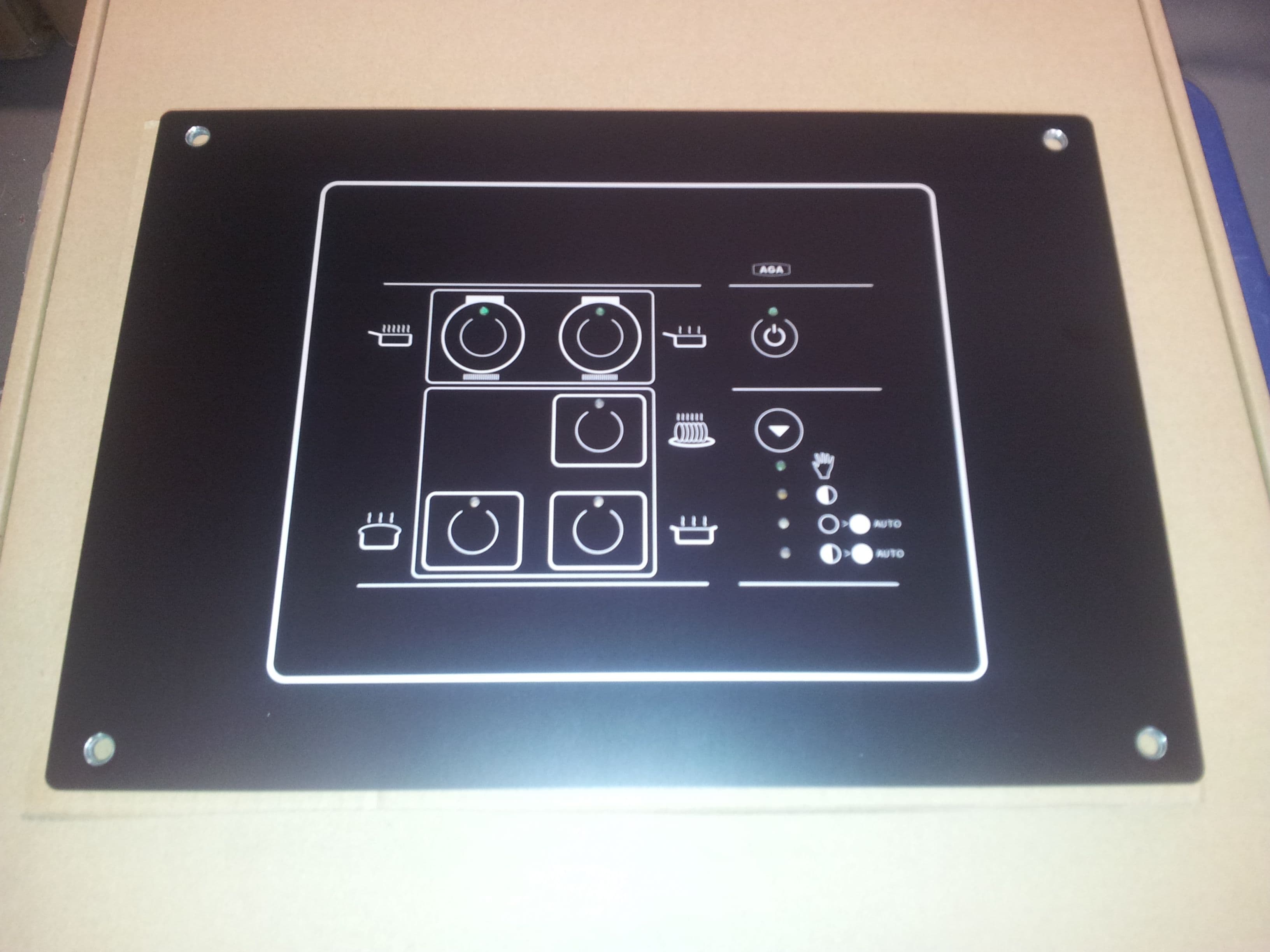
A2M-AGA-TC3TEK
Jul 02, 2014Low Powered Communication Device Fitted Into a Range Cooker
Equipment Class
DXT - Part 15 Low Power Transceiver, Rx Verified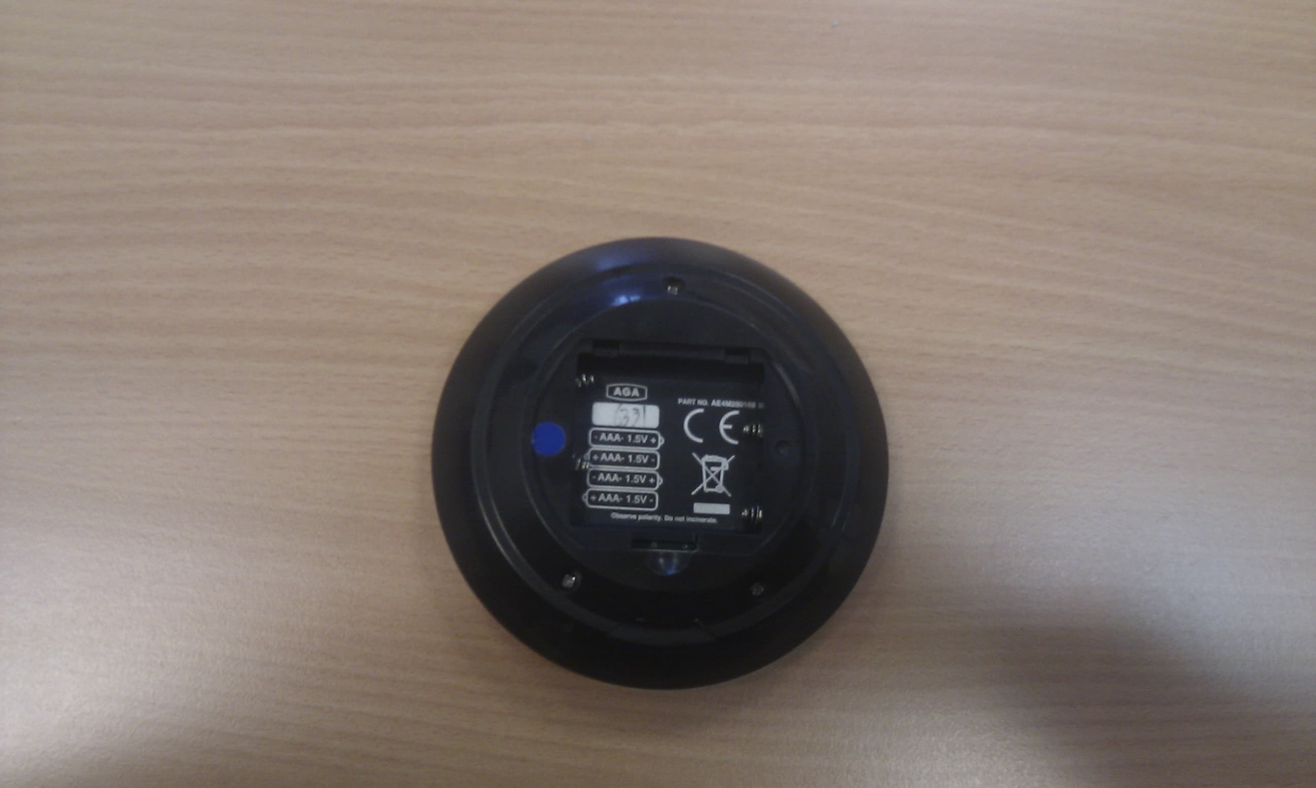
A2M-AGA-TC3
May 03, 2012Hand Held Cooking Control
Equipment Class
DXX - Part 15 Low Power Communication Device Transmitter