A4MLP-RF24DS-02LP-RF24DS-02
LOGICAL PRODUCT CORPORATION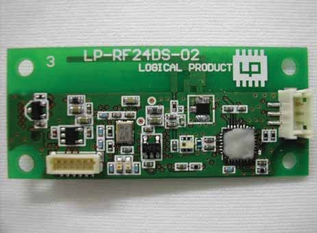
Click to zoom
Application Details
- Equipment Class
- DTS - Digital Transmission System
- Date of Grant
- Feb 01, 2012
- Application Purpose
- Original Equipment
- Date of Application
- Jan 31, 2012
- Equipment Note
- LP-RF24DS-02
- Frequency Range
- 2405.00000000 - 2479.00000000
- Company
- LOGICAL PRODUCT CORPORATION
- Country
- Japan
Documents & Files
Document Text
Text extracted from the exhibit documents filed with the FCC. Open a document above to read the original.
External Photos
㻸㻼㻙㻾㻲㻞㻠㻰㻿㻙㻜㻞㻌㻵㻺㼀㻱㻾㻺㻭㻸㻌㻼㻴㻻㼀㻻㻿 㻲㻾㻻㻺㼀 㻮㻭㻯㻷 㻸㻼㻙㻾㻲㻞㻠㻰㻿㻙㻜㻞㻌㻵㻺㼀㻱㻾㻺㻭㻸㻌㻼㻴㻻㼀㻻㻿㻝㻛㻞
ID Label/Location Info
㻸㻼㻙㻾㻲㻞㻠㻰㻿㻙㻜㻞㻌㻯㻱㻾㼀㻵㻲㻵㻯㻭㼀㻵㻻㻺㻌㻸㻭㻮㻱㻸 㻲㻯㻯㻌㻵㻰䠖㻌㻭㻠㻹㻸㻼㻙㻾㻲㻞㻠㻰㻿㻙㻜㻞 㻯㻭㻿㻱㻌㻰㻵㻹㻱㻺㻿㻵㻻㻺㻿㻌䠖䚷㻠㻜㽢㻡㻡㽢㻞㻜䚷㼙㼙 㻌㻯㼛㼚㼠㼍㼕㼚㼟㻌㻲㻯㻯㻌㻵㻰䠖㻌㻭㻠㻹㻸㻼㻙㻾㻲㻞㻠㻰㻿㻙㻜㻞 㻸㻼㻙㻾㻲㻞㻠㻰㻿㻙㻜㻞㻌㻯㻱㻾㼀㻵㻲㻵㻯㻭㼀㻵㻻㻺㻌㻸㻭㻮㻱㻸㻝㻛㻝
Internal Photos
㻸㻼㻙㻾㻲㻞㻠㻰㻿㻙㻜㻞㻌㻵㻺㼀㻱㻾㻺㻭㻸㻌㻼㻴㻻㼀㻻㻿 㻲㻾㻻㻺㼀 㻮㻭㻯㻷 㻸㻼㻙㻾㻲㻞㻠㻰㻿㻙㻜㻞㻌㻵㻺㼀㻱㻾㻺㻭㻸㻌㻼㻴㻻㼀㻻㻿㻝㻛㻞
RF Exposure Info
UL Japan, Inc. Head Office EMC Lab. 4383-326 Asama-cho, Ise-shi, Mie-ken 516-0021 JAPAN Telephone : +81 596 24 8116 Facsimile : +81 596 24 8124 Applicant: LOGICAL PRODUCT CORPORATION T ype of Equipment : LP-RF24DS-02 Model No. : LP-RF24DS-02 FCC ID: A4MLP-RF24DS-02 LOGICAL PRODUCT CORPORATION declares that Model : LP-RF24DS-02 ⇒ complies with FCC radiation exposure requirement specified in the FCC Rules 2.1091 (for mobile). RF Ex posure Calculations: ← The following information provides the minimum separation distance for the highest gain antenna provided with the “LP-RF24DS-02“ as calculated from FCC OET Bulletin 65 Appendix A, Table (B) Limits for General Population / Uncontrolled Exposure. This calculation is based on the highest EIRP possible from the system, considering maximum power and antenna gain, and considering a 1.0mW/cm^2 uncontrolled exposure limit. The Friis formula used was: S = (P * G) / (4* π * r 2 ) Where P = 1.78 mW (Maximum peak output power) G = 2.14 Numerical Antenna gain; equal to3.30dBi r =20.0 cm For: LP-RF24DS-02S =0.00076 mW/cm 2 No. : 32DE0080-HO-01 RF Exposure / MPE Calculation
Test Report
Test report No. : 32DE0080-HO-01-B Page : 2 of 26 Issued date : January 27, 2012 FCC ID : A4MLP-RF24DS-02 UL Japan, Inc. Head Office EMC Lab. 4383-326 Asama-cho, Ise-shi, Mie-ken 516-0021 JAPAN Telephone : +81 596 24 8116 Facsimile : +81 596 24 8124 CONTENTS PAGE SECTION 1: Customer information ......................................................................................................... 3 SECTION 2: Equipment under test (E.U.T.) ........................................................................................... 3 SECTION 3: Test specification, procedures & results ............................................................................ 4 SECTION 4: Operation of E.U.T. during testing .................................................................................... 7 SECTION 5: Radiated Spurious Emission .............................................................................................. 9 SECTION 6: 6dB Bandwidth, 99% Occupied Bandwidth, Peak Power Density ............................... 11 SECTION 7: Maximum Peak Output Power ........................................................................................ 12 APPENDIX 1: Data of EMI test .............................................................................................................. 13 6dB Bandwidth ................................................................................................................................. 13 Maximum Peak Output Power .......................................................................................................... 15 Radiated Spurious Emission ............................................................................................................. 16 Power Density ................................................................................................................................... 21 99%Occupied Bandwidth ................................................................................................................. 23 APPENDIX 2: Test instruments ............................................................................................................. 24 APPENDIX 3: Photographs of test setup ............................................................................................... 25 Radiated Spurious Emission ............................................................................................................. 25 Worst Case Position (Horizontal: Z-axis/ Vertical:Z-axis) ............................................................... 26 Test report No. : 32DE0080-HO-01-B Page : 3 of 26 Issued date : January 27, 2012 FCC ID : A4MLP-RF24DS-02 UL Japan, Inc. Head Office EMC Lab. 4383-326 Asama-cho, Ise-shi, Mie-ken 516-0021 JAPAN Telephone : +81 596 24 8116 Facsimile : +81 596 24 8124 SECTION 1: Customer information Company Name : LOGICAL PRODUCT CORPORATION Address : NAKAHARA BLDG.2F 2-25-5 MATOBA MINAMI-KU 811-1314 FUKUOKA JAPAN Telephone Number : +81-92-405-7603 Facsimile Number : +81-92-405-7604 Contact Person : YUICHIRO TANAKA SECTION 2: Equipment under test (E.U.T.) 2.1 Identification of E.U.T. Type of Equipment : LP-RF24DS-02 Model No. : LP-RF24DS-02 Serial No. : Refer to Section 4, Clause 4.2 Rating : DC5.0V Receipt Date of Sample : January 6, 2012 Country of Mass-production : Japan Condition of EUT : Production prototype (Not for Sale: This sample is equivalent to mass-produced items.) Modification of EUT : No Modification by the test lab 2.2 Product Description General Specification Clock frequency(ies) in the system : RF IC: 32MHz, CPU: 16MHz Radio Specification Radio Type : Transceiver Frequency of Operation : 2405-2479MHz Modulation : O-QPSK Power Supply (radio part input) : DC3.3V Antenna type : Inverted F Antenna Antenna Gain : 3.3dBi Test report No. : 32DE0080-HO-01-B Page : 4 of 26 Issued date : January 27, 2012 FCC ID : A4MLP-RF24DS-02 UL Japan, Inc. Head Office EMC Lab. 4383-326 Asama-cho, Ise-shi, Mie-ken 516-0021 JAPAN Telephone : +81 596 24 8116 Facsimile : +81 596 24 8124 SECTION 3: Test specification, procedures & results 3.1 Test Specification Test Specification : FCC Part 15 Subpart C: 2011, final revised on November 21, 2011 and effective December 21, 2011 Title : FCC 47CFR Part15 Radio Frequency Device Subpart C Intentional Radiators Section 15.207 Conducted limits Section 15.247 Operation within the bands 902-928MHz, 2400-2483.5MHz, and 5725-5850MHz 3.2 Procedures and results Item Test Procedure Specification Worst margin Results Remarks Conducted Emission FCC: ANSI C63.4:2003 7. AC powerline Conducted Emission measurements FCC: Section 15.207 N/A N/A*1) - IC: RSS-Gen 7.2.4 IC: RSS-Gen 7.2.4 6dB Bandwidth FCC: "Guidance on Measurement of Digital Transmission Systems Operating under Section15.247" FCC: Section 15.247(a)(2) See data. Complied Radiated *2) IC: RSS-Gen 4.6.2 IC: RSS-210 A8.2(a) Maximum Peak Output Power FCC: "Guidance on Measurement of Digital Transmission Systems Operating under Section15.247" FCC: Section 15.247(b)(3) Complied Radiated *2) IC: RSS-Gen 4.8 IC: RSS-210 A8.4(4) Power Density FCC: "Guidance on Measurement of Digital Transmission Systems Operating under Section15.247" FCC: Section 15.247 (e) Complied Radiated *2) IC: - IC: RSS-210 A8.2(b) Spurious Emission Restricted Band Edges FCC: "Guidance on Measurement of Digital Transmission Systems Operating under Section15.247" FCC: Section15.247(d) 5.2dB 2400.000MHz, AV, Vert. Complied Radiated *2) IC: RSS-Gen 4.9 IC: RSS-210 A8.5 RSS-Gen 7.2.3 Note: UL Japan, Inc.’s EMI Work Procedures No. 13-EM-W0420 and 13-EM-W0422. *1) The test is not applicable since the EUT does not have AC Mains. *2) All tests were performed with Radiated emission since the EUT does not have Antenna terminal. * In case any questions arise about test procedure, ANSI C63.4: 2003 is also referred. FCC 15.31 (e) The RF Module has its own regulator. The RF Module is constantly provided voltage (DC3.3V) through the regulator regardless of …
Text truncated - open the document above for the full version.
Test Setup Photos
Test report No. : 32DE0080-HO-01-B Page : 25 of 26 Issued date : January 27, 2012 FCC ID : A4MLP-RF24DS-02 UL Japan, Inc. Head Office EMC Lab. 4383-326 Asama-cho, Ise-shi, Mie-ken 516-0021 JAPAN Telephone : +81 596 24 8116 Facsimile : +81 596 24 8124 APPENDIX 3: Photographs of test setup Radiated Spurious Emission Photo 1 Photo 2 Test report No. : 32DE0080-HO-01-B Page : 26 of 26 Issued date : January 27, 2012 FCC ID : A4MLP-RF24DS-02 UL Japan, Inc. Head Office EMC Lab. 4383-326 Asama-cho, Ise-shi, Mie-ken 516-0021 JAPAN Telephone : +81 596 24 8116 Facsimile : +81 596 24 8124 Worst Case Position (Horizontal: Z-axis/ Vertical:Z-axis) X-axis Y-axis Z-axis
Contact Information
Applicant
DAISUKE YAMAMOTO(ENGINEER)
Technical Contact
UL Japan, Inc.Takahiro Hatakeda
[email protected]81-596-24-8116
4383-326 Asama-cho, Ise-shi · Mie-ken · Japan
Test Firm
UL Japan, Inc. Head office EMC Lab.Tetsuya Hashimoto
Technical Specifications
| # | Rule Parts | Frequency Range | Power Output |
|---|---|---|---|
| 1 | 15C | 2.40 GHz - 2.48 GHz | 1.80 mW |
Other Applications from LOGICAL PRODUCT CORPORATION
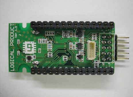
A4MLP-RF24DS-01
Feb 08, 2012LP-RF24DS-01
Equipment Class
DTS - Digital Transmission System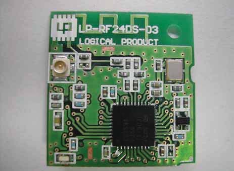
A4MLP-RF24DS-03
Feb 01, 2012LP-RF24DS-03
Equipment Class
DTS - Digital Transmission System