A5JC10150+Cam
QUADRANT TECHNOLOGY (SHENZHEN) CO., LTDApplication Details
- Equipment Class
- DTS - Digital Transmission System
- Date of Grant
- Dec 27, 2011
- Application Purpose
- Original Equipment
- Date of Application
- Dec 27, 2011
- Equipment Note
- +Cam
- Frequency Range
- 2422.00000000 - 2452.00000000
- Country
- China
Documents & Files
Document Text
Text extracted from the exhibit documents filed with the FCC. Open a document above to read the original.
Users Manual
1 +Cam Quick Start Guide 2 Regulatory Notices for USA This equipment has been tested and found to comply with the limits for a digital device, pursuant to Part 15 of the FCC Rules. These limits are designed to provide reasonable protection against harmful interference in a residential installation. This equipment generates, uses, and can radiate radio frequency energy and, if not installed and used in accordance with the instructions, may cause harmful interference to radio communications. However, there is no guarantee that interference will not occur in a particular installation. If this equipment does cause harmful interference to radio or television reception, which can be determined by turning the equipment off and on, the user is encouraged to try to correct the interference by one or more of the following measures: - Reorient or relocate the receiving antenna. - Increase the separation between the equipment and receiver. - Connect the equipment into an outlet on a circuit different from that to which the receiver is connected. - Consult the dealer or an experienced radio/TV technician for help. You are cautioned that any changes or modifications not expressly approved in this manual could void your authority to operate this equipment. The shielded interface cable recommended in this manual must be used with this equipment in order to comply with the limits for a digital device pursuant to Subpart B of Part 15 of FCC Rules. +Cam Quick Start Guide Camera Mounting To mount the +Cam to a wall, unscrew the base of the camera and remove the metal plate. With the included screws and anchors, fasten the mounting bracket on to the wall. Then, reattach the base cover and screw the stand back on to the mounting bracket. 3 +Cam Quick Start Guide 1. There’s an App for That T o get started, download the Seedonk app from Apple’s App store. 2. Connect the Camera Plug the +Ca m in to AC power with the supplied adapter before continuing. 4 +Cam Quick Start Guide 3. Wi-Fi Setup Mode Pl ease make sure the “Wi-Fi Setup” switch on the back of the camera is set to ON. 5 +Cam Quick Start Guide 3. Connect iPhone to +Cam Go to Setti ngs -> Wi-Fi on your iPhone and connect to the +Cam wireless network. 6 +Cam Quick Start Guide 4. Launch Seedonk App Once your iPhone establishes its connection to the +Cam, (usually takes around 30 seconds) launch the Seedonk App. The Seedonk app will automatically detect your +Cam. When prompted, click ‘Yes’ to setup your camera. 7 +Cam Quick Start Guide 4. Setup Wizard Follow the instructions in the Camera Setup Wizard to complete installation. 8 +Cam Quick Start Guide 5. Using Seedonk Please enter your user name and password, created during the setup process, in the login window to access your +Cam. 9 +Cam Quick Start Guide 6a. Seedonk Features – Main Window Configure Camera Camera Status 10 Friends’ Cameras Recorded Events App Settings +Cam Quick Start Guide 6b. Seedonk Features – Camera Viewer Ta k e a Snapshot Record a Video 11 +Cam Quick Start Guide 12 Safety Information Do not point the camera directly at the sun, else it will damage the image sensor. Keep the camera away from heat to avoid electric shocks. To prevent the chance of overheating and ruining the camera, do not cover/obstruct the ventilation holes at the top of the unit. Keep the camera away from rain or moisture. Do not attempt to open, dismantle, repair, or service the camera. Doing so may cause electric shocks and other hazards. Any evidence of misuse, abuse, or tampering will void the Limited Warranty. +Cam Quick Start Guide 13 For More Information To get the latest camera driver updates or to learn more about Imogen Studio products, please visit: www.imogenstudio.com To get software updates or to learn more about Seedonk, please visit: www.seedonk.com © ImogenStudio, 2012
External Photos
External of EUT
ID Label/Location Info
FCC ID Label FCC ID: A5JC10150 Model Number: QCP-A100 Made in China This device complies with Part 15 of the FCC Rules. Operation is subject to the following two conditions: (1) this device may not cause harmful interference, and (2) this device must accept any interference received, including interference that may cause undesired operation
ID Label/Location Info
Label Location Proposed Label Location on EUT
Internal Photos
Internal of EUT Antenna WIFI module
RF Exposure Info
RF EXPOSURE EVALUATION According to FCC 1.1310: The criteria listed in the following table shall be used to evaluate the environment impact of human exposure to radio frequency(RF) Radiation as specified in §1.1307(b) Limits for Maximum Permissible Exposure(MPE) Frequency Range(MHz) Electric Field Strength(V/m) Magnetic Field Strength(A/m) Power Density(mW/cm 2 ) Average Time (A) Limits for Occupational/Control Exposures 300-1500 -- -- F/300 6 1500-100000 -- -- 5 6 (B) Limits for General Population/Uncontrol Exposures 300-1500 -- -- F/1500 6 1500-100000 -- -- 1 30 11.1 Friis transmission formula: Pd=(Pout*G)\(4*pi*R 2 ) Where Pd= Power density in mW/cm 2 Pout=output power to antenna in mW G= gain of antenna in linear scale Pi=3.1416 R= distance between observation point and center of the radiator in cm Pd the limit of MPE, 1mW/cm 2 . If we know the maximum gain of the antenna and total power input to the antenna, through the calculation, we will know the distance where the MPE limit is reached. 11.2 Measurement Result Antenna gain: 1.3dBi 802.11b Channel Channel Frequency (MHz) Output Peak power (dBm) Output Peak power (mW) gain of antenna in linear scale G Power density at 20cm (mW/ cm 2 ) Power density Limits (mW/cm 2 ) 1 2412.00 10.090 10.209 1.350 0.003 1 6 2437.00 11.540 14.256 1.350 0.004 1 11 2462.00 11.830 15.241 1.350 0.004 1 802.11g Channel Channel Frequency (MHz) Output Peak power (dBm) Output Peak power (mW) gain of antenna in linear scale G Power density at 20cm (mW/ cm 2 ) Power density Limits (mW/cm 2 ) 1 2412.00 4.900 3.090 1.350 0.001 1 6 2437.00 6.960 4.966 1.350 0.001 1 11 2462.00 7.500 5.623 1.350 0.002 1 802.11n HT20 Channel Channel Frequency (MHz) Output Peak power (dBm) Output Peak power (mW) gain of antenna in linear scale G Power density at 20cm (mW/ cm 2 ) Power density Limits (mW/cm 2 ) 1 2412.00 5.160 3.281 1.350 0.001 1 6 2437.00 7.080 5.105 1.350 0.001 1 11 2462.00 7.500 5.623 1.350 0.002 1 802.11n HT40 Channel Channel Frequency (MHz) Output Peak power (dBm) Output Peak power (mW) gain of antenna in linear scale G Power density at 20cm (mW/ cm 2 ) Power density Limits (mW/cm 2 ) 3 2422.00 2.860 1.932 1.350 0.001 1 6 2437.00 4.370 2.735 1.350 0.001 1 9 2452.00 4.640 2.911 1.350 0.001 1
Test Report
SHENZHEN EMTEK CO., LTD. REPORT NO: ES111121101F FCC ID: A5JC10150 DATE: 12/14/2011 Page 1 of 69 ELECTROMAGNETIC EMISSIONS COMPLIANCE REPORT INTENTIONAL RADIATOR CERTIFICATION TO FCC PART 15 SUBPART C REQUIREMENT OF + Cam MODEL No.: QCP-A100, IP-200 FCC ID: A5JC10150 REPORT NO: ES111121101F ISSUE DATE: December 14, 2011 Prepared for QUADRANT TECHNOLOGY (SHENZHEN) CO., LTD 2nd Floor, 6th Building, CRS Industrial Park of Fangmapu Village, Guanlan Town, Baoan District, Shenzhen City, Guangdong Province, China Prepared by SHENZHEN EMTEK CO., LTD. Bldg 69, Majialong Industry Zone, Nanshan District, Shenzhen, Guangdong, China TEL: 86-755-26954280 FAX: 86-755-26954282 SHENZHEN EMTEK CO., LTD. REPORT NO: ES111121101F FCC ID: A5JC10150 DATE: 12/14/2011 Page 2 of 69 VERIFICATION OF COMPLIANCE Applicant: QUADRANT TECHNOLOGY (SHENZHEN) CO., LTD 2nd Floor, 6th Building, CRS Industrial Park of Fangmapu Village, Guanlan Town, Baoan District, Shenzhen City, Guangdong Province, China Manufacturer: QUADRANT TECHNOLOGY (SHENZHEN) CO., LTD 2nd Floor, 6th Building, CRS Industrial Park of Fangmapu Village, Guanlan Town, Baoan District, Shenzhen City, Guangdong Province, China Product Description: + Cam Model Number: QCP-A100, IP-200 (Note: Both model numbers are identical in circuitry and electrical, mechanical and physical construction; the only differences are the appearance trade name and model no. for trading purpose. We take QCP-A100 to test.) File Number: ES111121101F Date of Test: November 22, 2011 to December 10, 2011 We hereby certify that: The above equipment was tested by SHENZHEN EMTEK CO., LTD. The test data, data evaluation, test procedures, and equipment configurations shown in this report were made in accordance with the procedures given in ANSI C63.4 (2009) and the energy emitted by the sample EUT tested as described in this report is in compliance with conducted and radiated emission limits of FCC Rules Part 15.247. The test results of this report relate only to the tested sample identified in this report. Date of Test : November 22, 2011 to December 10, 2011 Prepared by : (Engineer) Reviewer : (Quality Manager) Approve & Authorized Signer : (Manager) SHENZHEN EMTEK CO., LTD. REPORT NO: ES111121101F FCC ID: A5JC10150 DATE: 12/14/2011 Page 3 of 69 Ta b l e o f C o n t e n t s 1. GENERAL INFORMATION................................................................................................... 5 1.1 P RODUCT DESCRIPTION......................................................................................................... 5 1.2 R ELATED SUBMITTAL(S) / GRANT(S) ..................................................................................... 5 1.3 T EST METHODOLOGY............................................................................................................ 6 1.4 S PECIAL ACCESSORIES.......................................................................................................... 6 1.5 E QUIPMENT MODIFICATIONS................................................................................................. 6 1.6 T EST FACILITY...................................................................................................................... 6 2. SYSTEM TEST CONFIGURATION...................................................................................... 7 2.1 EUT CONFIGURATION........................................................................................................... 7 2.2 EUT EXERCISE...................................................................................................................... 7 2.3 T EST PROCEDURE.................................................................................................................. 7 2.4 C ONFIGURATION OF TESTED SYSTEM.................................................................................... 7 3. DESCRIPTION OF TEST MODES ........................................................................................ 9 4. SUMMARY OF TEST RESULTS ......................................................................................... 10 5. CONDUCTED EMISSIONS TEST....................................................................................... 11 5.1 M EASUREMENT PROCEDURE............................................................................................... 11 5.2 T EST SET-UP (BLOCK DIAGRAM OF CONFIGURATION)....................................................... 11 5.3 M EASUREMENT EQUIPMENT USED...................................................................................... 11 5.4 C ONDUCTED EMISSION LIMIT............................................................................................. 12 5.5 M EASUREMENT RESULT...................................................................................................... 12 5.6 C ONDUCTED MEASUREMENT PHOTO.................................................................................. 13 6. RADIATED EMISSION TEST.............................................................................................. 14 6.1 M EASUREMENT PROCEDURE............................................................................................... 14 6.2 T EST SET-UP (BLOCK DIAGRAM OF CONFIGURATION)....................................................... 14 6.3 M EASUREMENT EQUIPMENT USED...................................................................................... 15 6.4 R ADIATED EMISSION LIMIT................................................................................................. 15 6.5 M EASUREMENT RESULT...................................................................................................... 17 6.6 R ADIATED MEASUREMENT PHOTOS.................................................................................... 41 7. OCCUPIED BANDWIDTH TEST........................................................................................ 43 7.1 M EASUREMENT PROCEDURE................................................…
Text truncated - open the document above for the full version.
Test Setup Photos
RADIATED EMISSION TEST CONDUCTED EMISSION TEST
Contact Information
Applicant
Anhong Gao(Manufacture Manager)
Test Firm
EMTEK (Shenzhen) Co., Ltd.David Lee
Technical Specifications
| # | Rule Parts | Frequency Range | Power Output |
|---|---|---|---|
| 2 | 15C | 2.42 GHz - 2.45 GHz | 2.90 mW |
Other Applications from QUADRANT TECHNOLOGY (SHENZHEN) CO., LTD
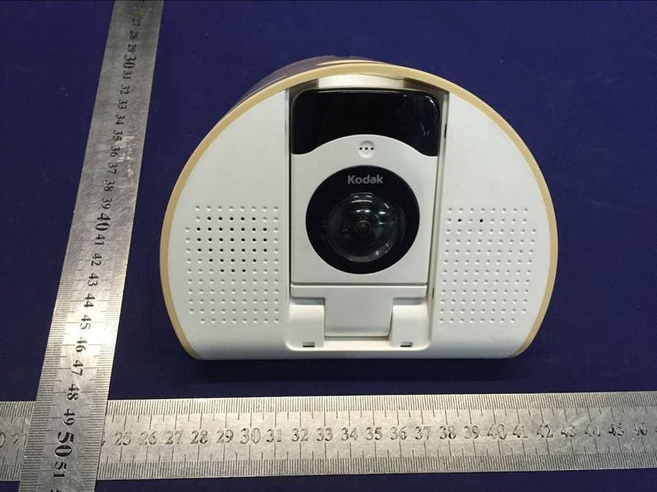
A5JA09529
Dec 20, 2015Baby Audio Monitor
Equipment Class
DXT - Part 15 Low Power Transceiver, Rx Verified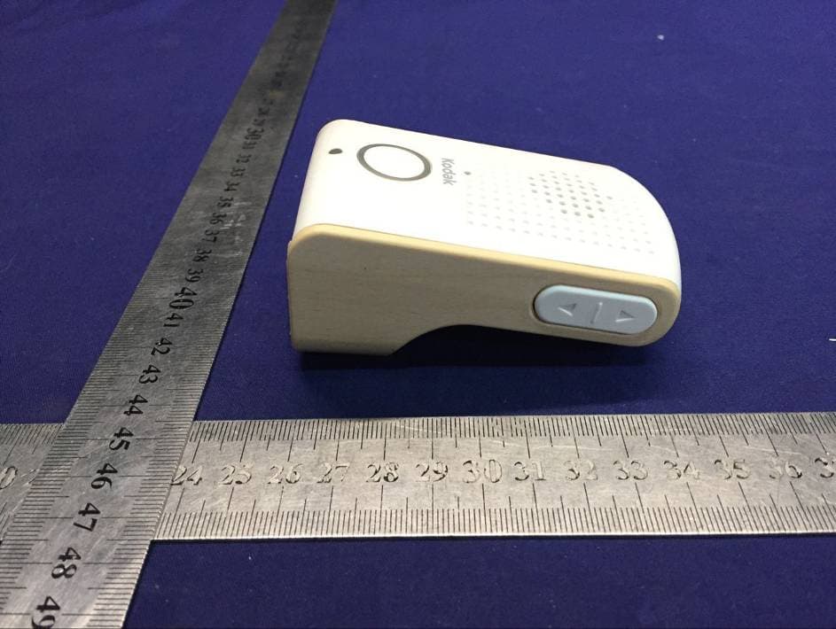
A5JA10529
Dec 20, 2015Baby Audio Monitor
Equipment Class
DXT - Part 15 Low Power Transceiver, Rx Verified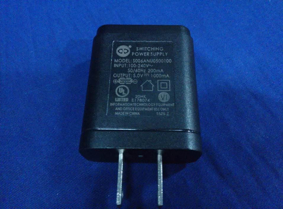
A5JC50527
Sep 22, 2015Video Monitor
Equipment Class
DTS - Digital Transmission System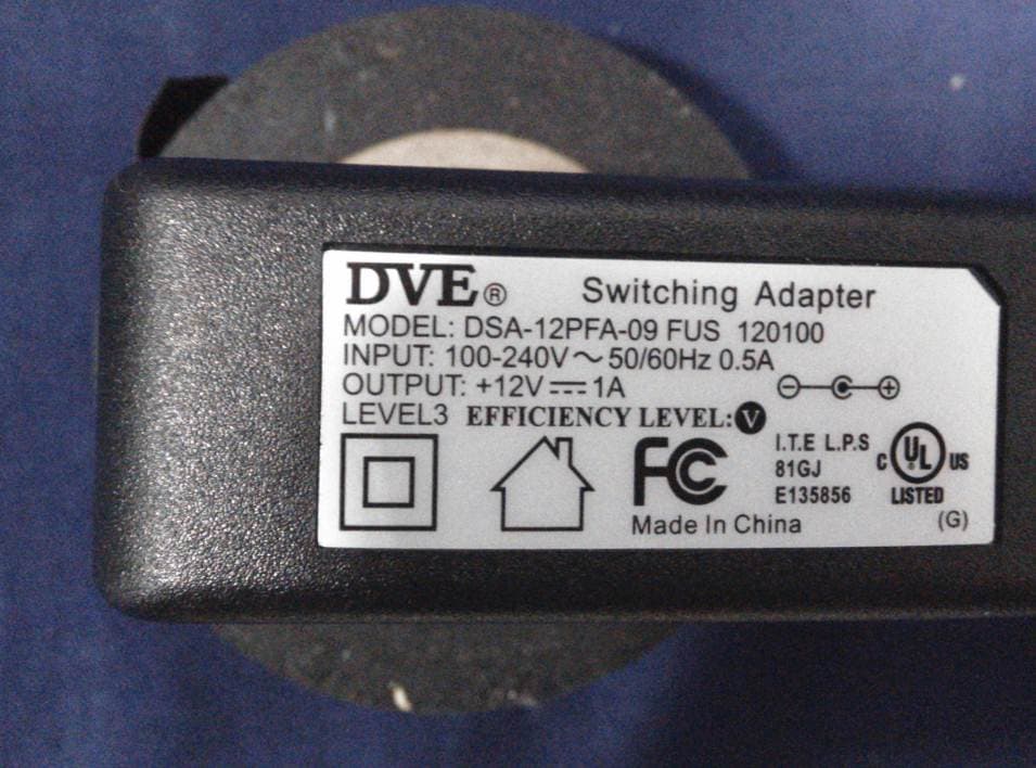
A5JC42421
Nov 26, 2014+Cam Outdoor HD/+CAM-HD-AW
Equipment Class
DTS - Digital Transmission System
A5JC31410
Jul 24, 2014+CAM ROBOT-O HD/+CAM PT
Equipment Class
DTS - Digital Transmission System