A5JC31410+CAM ROBOT-O HD/+CAM PT
QUADRANT TECHNOLOGY (SHENZHEN) CO., LTD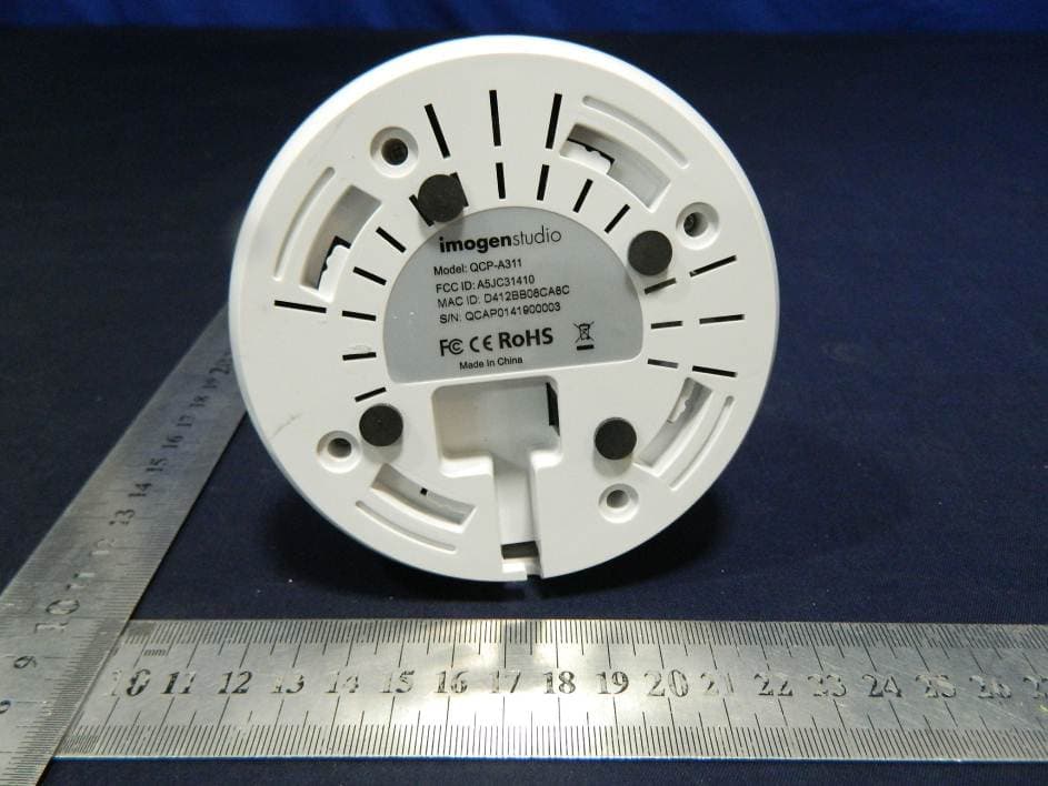
Click to zoom
Application Details
- Equipment Class
- DTS - Digital Transmission System
- Date of Grant
- Jul 24, 2014
- Application Purpose
- Original Equipment
- Date of Application
- Jul 23, 2014
- Equipment Note
- +CAM ROBOT-O HD/+CAM PT
- Frequency Range
- 2412.00000000 - 2462.00000000
- Country
- China
Documents & Files
Document Text
Text extracted from the exhibit documents filed with the FCC. Open a document above to read the original.
Users Manual
+CAM Robot-o HD Quick Start Guide 2 CAUTION RISK OF ELECTRIC SHOCK DO NOT OPEN CAUTION TO REDUCE THE RISK OF ELECTRIC SHOCK, DO NOT REMOVE COVER (OR BACK). NO USER SERVICEABLE PARTS INSIDE, REFER SERVICING TO QUALIFIED SERVICE PERSONNEL. This symbol is intended to alert the user to the presence of uninsulated “dangerous voltage” within the product’s enclosure that may be of sufficient magnitude to constitute a risk of electric shock to persons. The exclamation point within an equilateral triangle is intended to alert the user to the presence of important operating and maintenance (servicing) instructions in the literature accompanying the product. Warning To prevent Fire or Shock Hazards, Do Not Expose This PRODUCT to Rain or Moisture. Apparatus shall not be exposed to dripping or splashing and no object filled with liquids, such as vases, shall be placed on the apparatus. To avoid electrical shock, do not open the cabinet. Refer servicing to qualified personnel only. +CAM Robot-o HDQuick Start Guide 3 Regulatory Notices for USA This equipment has been tested and found to comply with the limits for a digital device, pursuant to Part 15 of the FCC Rules. These limits are designed to provide reasonable protection against harmful interference in a residential installation. This equipment generates, uses, and can radiate radio frequency energy and, if not installed and used in accordance with the instructions, may cause harmful interference to radio communications. However, there is no guarantee that interference will not occur in a particular installation. If this equipment does cause harmful interference to radio or television reception, which can be determined by turning the equipment off and on, the user is encouraged to try to correct the interference by one or more of the following measures: - Reorient or relocate the receiving antenna. - Increase the separation between the equipment and receiver. - Connect the equipment into an outlet on a circuit different from that to which the receiver is connected. - Consult the dealer or an experienced radio/TV technician for help. You are cautioned that any changes or modifications not expressly approved in this manual could void your authority to operate this equipment. The shielded interface cable recommended in this manual must be used with this equipment in order to comply with the limits for a digital device pursuant to Subpart B of Part 15 of FCC Rules. The device has been evaluated to meet general RF exposure requirement. The device can be used in portable exposure condition without restriction. +CAM Robot-o HD Quick Start Guide 4 Camera Mounting To mount the +CAM Robot-o HD to the wall, place the camera in a position to ensure the most comprehensive view for video monitoring. Unscrew the base of the camera and remove the plate. The dots on the base of the camera indicate the location of the expansion bolts. Insert the expansion bolts into the drilled holes. Use a screwdriver to tighten or loosen the screws and secure the +CAM Robot-o HD. Connect the device cables. +CAM Robot-o HDQuick Start Guide 5 1. iSecurity+ App To get started, download the iSecurity+ app from Apple’s App store or the Google Play Store. 2. Connect to Power Connect the +CAM Robot-o HDto the AC power adapter, then plug your power cord into the electrical outlet. +CAM Robot-o HD Quick Start Guide 6 3a. Wi-Fi Setup Mode The Setup button will glow the green. The “Wi-Fi Setup” LEDs in the front of the cam will twinkle the green/orange alternatively and the +CAM Robot-o HD will rotate when the camera is ready for setup. (This may take up to 2 minutes when the camera is first powered on.) +CAM Robot-o HDQuick Start Guide 7 3b. Connect device to +CAM Robot-o HD iOS Android Go to your device’s settings -> Under the Wi-Fi setting, connect to the RobotoHDXXXX (last 4 digits of Cam ID)network. +CAM Robot-o HD Quick Start Guide 8 4a. Launch iSecurity+ App Once your device establishes its connection to the +CAM Robot-o HD, (usually takes around 30 seconds,) launch the iSecurity+ App. If you don’t see the pop up prompt, please close the app and re-launch it. iSecurity+ app will automatically detect your camera. When prompted, click ‘Yes’ to setup your camera. +CAM Robot-o HDQuick Start Guide 9 4b. Setup Wizard Follow the instructions in the Camera SetupWizard to complete installation. +CAM Robot-o HD Quick Start Guide 10 4c. Setup Wizard Final Step Camera setup is complete. Press the reset/power button on the back of the camera to turn off Wi-Fi setup mode and to connect to your Wi-Fi network. Restart iSecurity+ and please log in again. Turn off Wi-Fi setup Setup Complete You can use your iOS/ Android devices to access the camera anywhere in the world. Make sure your phone has access to the internet via 3G, 4G orWi-Fi for internet connection. +CAM Robot-o HDQuick Start Guide 11 5. Using iSecurity+&Main Features Window Please enter your user name and password, created during the setup process to access your +CAM Robot-o HD. Friends’ Cameras Recorded Events App Settings Camera Status Configure Camera +CAM Robot-o HD Quick Start Guide 12 6. iSecurity+ Features – Camera Viewer Swipe directional controls to change the camera Pan & Tilt view. Audio Muting Off/On Ta k e a Snapshot Audio-only Mode Record a video clip +CAM Robot-o HDQuick Start Guide 13 6a. Zoom Function Zooming In - Touch the screen with two fingers and slide inward at an angle and the image will zoom in. Zooming Out - Touch the screen with two fingers and slide outwards at an angle and it will enlarge the image. +CAM Robot-o HD Quick Start Guide 14 6a. Audio Talkback 1. To use Audio Talkback, first press the Audio button to initiate sound to listen in. 2. Then press the Audio Talkback button and speak into your device, then let go for the audio to transfer to the camera’s speaker. +CAM Robot-o HDQuick Start Guide 15 Safety Information Do not point the camera directly at the sun, or else it will damage the image sensor. Kee…
Text truncated - open the document above for the full version.
Cover Letter(s)
SCS-F18: Project and Product Certification Representative Authorization Letter Page 1 of 3 Rev 4.0 775 Montague Expressway Milpitas, CA 95035 Tel: 408-526-1188 Fax: 408-526-1088 Email: [email protected] Project and Product Certification Representative Authorization Letter Reason for Amendment (current / obsolete) Revision History Approved Date From To Initial Release (obsolete) 1.0 1.0 Nov-14-2006 Revised wording (obsolete) 1.0 2.0 Sept–25-2007 Updated company template (obsolete) 2.0 3.0 Jan-31-2012 Updated letter information (current) 3.0 4.0 May-23-2014 SCS-F18: Project and Product Certification Representative Authorization Letter Page 2 of 3 Rev 4.0 Quadrant Technology(Shenzhen) Co., Ltd. 2014-06-18 To: SIEMIC, INC. 775 Montague Expressway, Milpitas, CA 95035 USA Dear Sir/Madam, Re: Product Certification Representative Authorization Letter We, Quadrant Technology(Shenzhen) Co., Ltd._ hereby authorize SIEMIC, Inc. to act as a Certification Body for certifying for the following project(s): FCC ID: A5JC31410 +CAM ROBOT-O HD/+CAM PT; Model Number: QCP-A311, QCP-A310 Sincerely, Signature Youyi Huang / Buyer E-mail: [email protected] Phone: 86-755-27418005 Fax: 86-755-27418010 Address 3rd floor, 7TH building, Hongfa JiaTeLi Hi-Tech park of ShiXin Village, Shiyan Town, Shenzhen City, Guangdong province, China. SCS-F18: Project and Product Certification Representative Authorization Letter Page 3 of 3 Rev 4.0 Quadrant Technology(Shenzhen) Co., Ltd. 2014-06-18 To: SIEMIC, Inc. 775 Montague Expressway, Milpitas, CA 95035 USA Dear Sir/Madam, Re: Project and Product Certification Representative Authorization Letter We, Quadrant Technology(Shenzhen) Co., Ltd.__hereby authorize SIEMIC, Inc. to act as Certification Body for certifying for the following project(s): FCC ID: A5JC31410 +CAM ROBOT-O HD/+CAM PT; Model Number: QCP-A311, QCP-A310 We affirm that between SIEMIC, Inc. and Quadrant Technology(Shenzhen) Co., Ltd._ any difference in understanding, including test plan, measurement methods, applicable standards and relevant procedures and processes have been resolved prior to commencement of testing activities. Sincerely, Signature Youyi Huang / Buyer E-mail: [email protected] Phone: 86-755-27418005 Fax: 86-755-27418010 Address 3rd floor, 7TH building, Hongfa JiaTeLi Hi-Tech park of ShiXin Village, Shiyan Town, Shenzhen City, Guangdong province, China.
Cover Letter(s)
SCS-F19: Confidentiality Request Letter Page 1 of 2 Rev 3.0 775 Montague Expressway Milpitas, CA 95035 Tel: 408-526-1188 Fax: 408-526-1088 Email: [email protected] Confidentiality Request Letter Reason for Amendment (current / obsolete) Revision History Approved Date From To Initial Release (obsolete) 1.0 1.0 Nov-14-2006 Adding CFR 2.459 (obsolete) 1.0 2.0 August – 11 - 2008 Updated company template & Added text box (current) 2.0 3.0 Jan-31-2012 SCS-F19: Confidentiality Request Letter Page 2 of 2 Rev 3.0 Quadrant Technology(Shenzhen) Co., Ltd. 2014-06-16 To: Federal Communications Commission Authorization and Evaluation Division 7435 Oakland Mills Road Columbia, MD Subject: Permanent Confidentiality Request for FCC ID: A5JC31410 We hereby request confidential treatment of information accompanying this application as outlined below: - Block Diagram - Schematics - Operational Description The above materials contain trade secrets and proprietary information not customarily released to the public. The public disclosure of these materials may be harmful to the applicant and provide unjustified benefits to its competitors. The applicant understands that pursuant to Section 0.457 & 0.459 of the Rules, disclosure of this application and all accompanying documentation will not be made before the date of the Grant for this application. Sincerely, Signature Youyi Huang / Buyer E-mail: [email protected] Phone: 86-755-27418005 Fax: 86-755-27418010 Address 3rd floor, 7TH building, Hongfa JiaTeLi Hi-Tech park of ShiXin Village, Shiyan Town, Shenzhen City, Guangdong province, China.
Cover Letter(s)
Quadrant Technology(Shenzhen) Co., Ltd. 2014-07-02 To: Federal Communications Commission 7435 Oakland Mills Road Columbia, MD FCC ID: A5JC31410 To Whom It May Concern: This letter is to ascertain that Quadrant Technology(Shenzhen) Co., Ltd. FCC ID: A5JC31410 +CAM ROBOT-O HD/+CAM PT, Model No.: QCP-A311, QCP-A310 has been the units used for conducting FCC compliance testing, the DoC part will be tested by FCC recognized test lab. If you have any question or concerns, pls. contact us. Sincerely, Signature Youyi Huang / Buyer E-mail: [email protected] Phone: 86-755-27418005 Fax: 86-755-27418010 Address 3rd floor, 7TH building, Hongfa JiaTeLi Hi-Tech park of ShiXin Village, Shiyan Town, Shenzhen City, Guangdong province, China.
Cover Letter(s)
Family models declaration letter. 2014-06-16 We Quadrant Technology(Shenzhen) Co., Ltd. Of 3rd floor, 7TH building, Hongfa JiaTeLi Hi-Tech park of ShiXin Village, Shiyan Town, Shenzhen City, Guangdong province, China. (address) Declare under our sole responsibility that the product Product: +CAM ROBOT-O HD/+CAM PT Model Number :QCP-A311, QCP-A310 All models have the same constructions, circuit diagram and PCB layout. Only model name and trade name are different. Unless otherwise stated Thanks Sincerely, Signature Youyi Huang / Buyer E-mail: [email protected] Phone: 86-755-27418005 Fax: 86-755-27418010 Address: 3rd floor, 7TH building, Hongfa JiaTeLi Hi-Tech park of ShiXin Village, Shiyan Town, Shenzhen City, Guangdong province, China.
ID Label/Location Info
Made In China Model: QCP-A311 FCC ID:A5JC31410 MAC ID:D412BBXXXXXX S/N:QCAP01242XXXXX
ID Label/Location Info
Location
Internal Photos
Antenna1 Wifi Module Antenna2
RF Exposure Info
FCC ID : A5JC31410 RF EXPOSURE EVALUATION According to FCC 1.1310: The criteria listed in the following table shall be used to evaluate the environment impact of human exposure to radio frequency(RF) Radiation as specified in §1.1307(b) Limits for Maximum Permissible Exposure (MPE) Frequency Range(MHz) Electric Field Strength(V/m) Magnetic Field Strength(A/m) Power Density(mW/cm 2 ) Average Time (A) Limits for Occupational/Control Exposures 300-1500 -- -- F/300 6 1500-100000 -- -- 5 6 (B) Limits for General Population/Uncontrol Exposures 300-1500 -- -- F/1500 6 1500-100000 -- -- 1 30 11.1 Friis transmission formula: Pd= (Pout*G)\ (4*pi*R 2 ) Where Pd= Power density in mW/cm 2 Pout=output power to antenna in mW G= Numeric gain of the antenna relative to isotropic antenna Pi=3.1416 R= distance between observation point and center of the radiator in cm Pd the limit of MPE, 1mW/cm 2 . If we know the maximum gain of the antenna and total power input to the antenna, through the calculation, we will know the distance where the MPE limit is reached. 11.2 Measurement Result Operation Frequency: WIFI 802.11b/g/n HT20: 2412-2462MHz, 802.11n HT40: 2422-2452MHz Power density limited: 1mW/ cm 2 Antenna gain: Chain A: 2dBi, Chain B: 2dBi, Directional Gain= G ANT +10log(N ANT )dBi=5dBi (MIMO) 802.11b: Channel Channel Frequency (MHz) Output power (dBm) Output power (mW) Antenna Gain Numeric Power density at 20cm(mW/cm 2 ) Power density Limits (mW/cm2 ) 1 2412 19.17 82.6038 1.5849 0.0260 1 6 2437 19.61 91.4113 1.5849 0.0288 1 11 2462 20.39 109.39561.5849 0.0345 1 802.11g: Channel Channel Frequency (MHz) Output power (dBm) Output power (mW) Antenna Gain Numeric Power density at 20cm(mW/cm 2 ) Power density Limits (mW/cm2 ) 1 2412 22.37 172.58381.5849 0.0544 1 6 2437 22.91 195.43391.5849 0.0616 1 11 2462 23.11 204.64451.5849 0.0645 1 802.11n HT20 Chain A: Channel Channel Frequency (MHz) Output power (dBm) Output power (mW) Antenna Gain Numeric Power density at 20cm(mW/cm 2 ) Power density Limits (mW/cm2 ) 1 2412 22.45 175.79241.5849 0.0554 1 6 2437 22.78 189.67061.5849 0.0598 1 11 2462 22.98 198.60951.5849 0.0626 1 802.11n HT20 Chain B: Channel Channel Frequency (MHz) Output power (dBm) Output power (mW) Antenna Gain Numeric Power density at 20cm(mW/cm 2 ) Power density Limits (mW/cm2 ) 1 2412 19.45 88.10491.5849 0.0278 1 6 2437 20.10 102.32931.5849 0.0323 1 11 2462 20.55 113.50111.5849 0.0358 1 802.11n HT20 MIMO: Channel Channel Frequency (MHz) Power density at 20cm(mW/cm 2 ) Chain A Power density at 20cm(mW/cm 2 ) Chain B Power density at 20cm(mW/cm 2 ) ChainA+B Power density Limits (mW/cm2 ) 1 2412 0.0554 0.0278 0.0832 1 6 2437 0.0598 0.0323 0.0921 1 11 2462 0.0626 0.0358 0.0984 1 802.11n HT40 Chain A: Channel Channel Frequency (MHz) Output power (dBm) Output power (mW) Antenna Gain Numeric Power density at 20cm(mW/cm 2 ) Power density Limits (mW/cm2 ) 3 2422 21.39 137.72091.5849 0.0434 1 6 2437 21.52 141.90581.5849 0.0447 1 9 2452 21.72 148.59361.5849 0.0469 1 802.11n HT40 Chain B: Channel Channel Frequency (MHz) Output power (dBm) Output power (mW) Antenna Gain Numeric Power density at 20cm(mW/cm 2 ) Power density Limits (mW/cm2 ) 3 2422 18.35 68.39121.5849 0.0216 1 6 2437 18.60 72.44361.5849 0.0228 1 9 2452 18.77 75.33561.5849 0.0238 1 802.11n HT40 MIMO: Channel Channel Frequency (MHz) Power density at 20cm(mW/cm 2 ) Chain A Power density at 20cm(mW/cm 2 ) Chain B Power density at 20cm(mW/cm 2 ) ChainA+B Power density Limits (mW/cm2 ) 3 2422 0.0434 0.0216 0.065 1 6 2437 0.0447 0.0228 0.0675 1 9 2452 0.0469 0.0238 0.0707 1
Test Report
TRF No.: FCC 15.247/A Page 1 of 64 Report No.: ES140523238E Ver.1.0 Shenzhen EMTEK Co.,Ltd. Building 69, Majialong Industry Zone, Nanshan District, Shenzhen,Guangdong,China www.emtek.com.cn Tel: +86-755-2695 4280 Fax: +86-755-2695 4282 Access to the World ELECTROMAGNETIC EMISSIONS COMPLIANCE REPORT INTENTIONAL RADIATOR CERTIFICATION TO FCC PART 15 SUBPART C REQUIREMENT OF +CAM ROBOT-O HD/+CAM PT MODEL No.: QCP-A311, QCP-A310 FCC ID: A5JC31410 REPORT NO.: ES140523238E ISSUE DATE: July 2, 2014 Prepared for Quadrant Technology(Shenzhen) Co., Ltd. 3rd floor, 7TH building, Hongfa JiaTeLi Hi-Tech park of ShiXin Village, Shiyan Town, Shenzhen City, Guangdong province, China. Prepared by SHENZHEN EMTEK CO., LTD. Bldg 69, Majialong Industry Zone, Nanshan District, Shenzhen, Guangdong, China TEL: 86-755-26954280 FAX: 86-755-26954282 TRF No.: FCC 15.247/A Page 2 of 64 Report No.: ES140523238E Ver.1.0 Shenzhen EMTEK Co.,Ltd. Building 69, Majialong Industry Zone, Nanshan District, Shenzhen,Guangdong,China www.emtek.com.cn Tel: +86-755-2695 4280 Fax: +86-755-2695 4282 Access to the World VERIFICATION OF COMPLIANCE Applicant: Quadrant Technology(Shenzhen) Co., Ltd. 3rd floor, 7TH building, Hongfa JiaTeLi Hi-Tech park of ShiXin Village, Shiyan Town, Shenzhen City, Guangdong province, China. Manufacturer: Quadrant Technology(Shenzhen) Co., Ltd. 3rd floor, 7TH building, Hongfa JiaTeLi Hi-Tech park of ShiXin Village, Shiyan Town, Shenzhen City, Guangdong province, China. Product Description: +CAM ROBOT-O HD/+CAM PT Model Number: QCP-A311, QCP-A310 Trade mark Imogenstudio File Number: ES140523238E Date of Test: May 24, 2014 to July 2, 2014 We hereby certify that: The above equipment was tested by SHENZHEN EMTEK CO., LTD. The test data, data evaluation, test procedures, and equipment configurations shown in this report were made in accordance with the procedures given in ANSI C63.4 (2009) and the energy emitted by the sample EUT tested as described in this report is in compliance with conducted and radiated emission limits of FCC Rules Part 15.247. The test results of this report relate only to the tested sample identified in this report. Date of Test : May 24, 2014 to July 2, 2014 Prepared by : Jack Li/Editor Reviewer : Joe Xia/Supervisor Approve & Authorized Signer : Lisa Wang/Manager TRF No.: FCC 15.247/A Page 3 of 64 Report No.: ES140523238E Ver.1.0 Shenzhen EMTEK Co.,Ltd. Building 69, Majialong Industry Zone, Nanshan District, Shenzhen,Guangdong,China www.emtek.com.cn Tel: +86-755-2695 4280 Fax: +86-755-2695 4282 Access to the World Table of Contents 1. GENERAL INFORMATION ...................................................................................................................... 5 1.1 PRODUCT DESCRIPTION ...................................................................................................................... 5 1.2 RELATED SUBMITTAL(S) / GRANT(S) ..................................................................................................... 5 1.3 TEST METHODOLOGY .......................................................................................................................... 6 1.4 SPECIAL ACCESSORIES ........................................................................................................................ 6 1.5 EQUIPMENT MODIFICATIONS................................................................................................................. 6 1.6 TEST FACILITY ..................................................................................................................................... 6 2. SYSTEM TEST CONFIGURATION ......................................................................................................... 7 2.1 EUT CONFIGURATION .......................................................................................................................... 7 2.2 EUT EXERCISE ................................................................................................................................... 7 2.3 TEST PROCEDURE ............................................................................................................................... 7 2.4 CONFIGURATION OF TESTED SYSTEM ................................................................................................... 7 3. DESCRIPTION OF TEST MODES ........................................................................................................... 9 4. SUMMARY OF TEST RESULTS ............................................................................................................ 10 5. CONDUCTED EMISSIONS TEST ......................................................................................................... 11 5.1 MEASUREMENT PROCEDURE ............................................................................................................. 11 5.2 TEST SET-UP (BLOCK DIAGRAM OF CONFIGURATION) ........................................................................ 11 5.3 MEASUREMENT EQUIPMENT USED ..................................................................................................... 11 5.4 CONDUCTED EMISSION LIMIT ............................................................................................................. 11 5.5 MEASUREMENT RESULT ..................................................................................................................... 12 6. RADIATED EMISSION TEST ................................................................................................................. 14 6.1 MEASUREMENT PROCEDURE ............................................................................................................. 14 6.2 TEST SET-UP (BLOCK DIAGRAM OF CONFIGURATION) ........................................................................ 14 6.3 MEASUREMENT EQUIPMENT USED ..................................................................................................... 16 6.4 RADIATED EMISSION LIMIT .......…
Text truncated - open the document above for the full version.
Test Setup Photos
LINE CONDUCTED EMISSION TEST Adaper1: Adaper2: RADIATED EMISSION TEST Adapter1: Adapter2:
Contact Information
Applicant
Anhong Gao(Manufacture Manager)
Test Firm
EMTEK (Shenzhen) Co., Ltd.David Lee
Technical Specifications
| # | Rule Parts | Frequency Range | Power Output |
|---|---|---|---|
| 1 | 15C | 2.41 GHz - 2.46 GHz | 311.80 mW |
Other Applications from QUADRANT TECHNOLOGY (SHENZHEN) CO., LTD
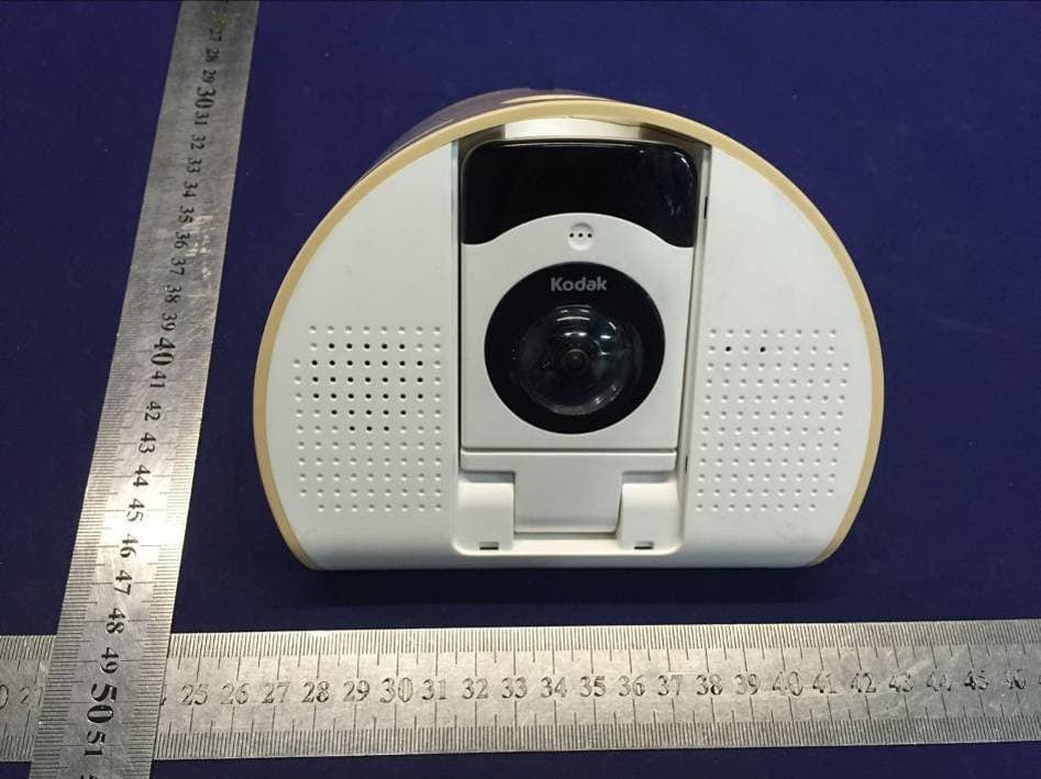
A5JA09529
Dec 20, 2015Baby Audio Monitor
Equipment Class
DXT - Part 15 Low Power Transceiver, Rx Verified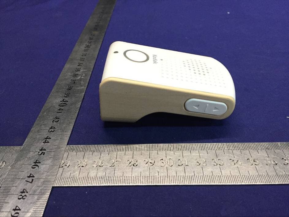
A5JA10529
Dec 20, 2015Baby Audio Monitor
Equipment Class
DXT - Part 15 Low Power Transceiver, Rx Verified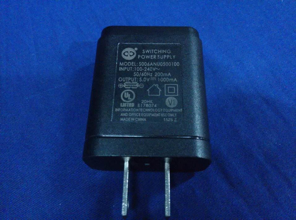
A5JC50527
Sep 22, 2015Video Monitor
Equipment Class
DTS - Digital Transmission System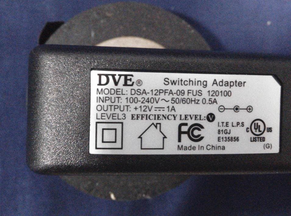
A5JC42421
Nov 26, 2014+Cam Outdoor HD/+CAM-HD-AW
Equipment Class
DTS - Digital Transmission System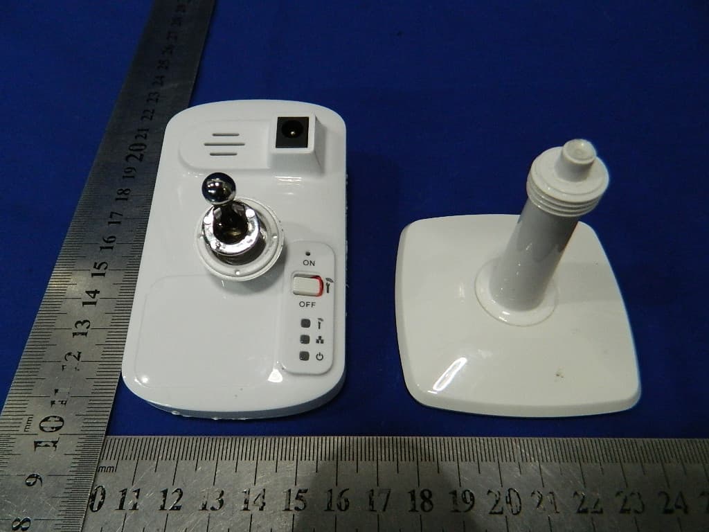
A5JC20313
Jun 05, 2013Plus CAM Pro/ Plus CAM Pro HD
Equipment Class
DTS - Digital Transmission System