A5LRTL8188EUSRTL8188EUS WIFI module
RF-LINK INTERNATIONAL LIMITED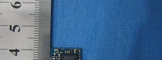
Click to zoom
Application Details
- Equipment Class
- DTS - Digital Transmission System
- Date of Grant
- Dec 09, 2012
- Application Purpose
- Original Equipment
- Date of Application
- Dec 06, 2012
- Equipment Note
- RTL8188EUS WIFI module
- Frequency Range
- 2422.00000000 - 2452.00000000
- Country
- China
Documents & Files
Document Text
Text extracted from the exhibit documents filed with the FCC. Open a document above to read the original.
Users Manual
http://www.rf-link.net RL-UM12BS V1.0 Product Specifications WLAN 11b/g/n USB module (1T1R) Version: V1.0 http://www.rf-link.net Overview UM12BS is a WLAN 11n USB module, which fully supports the features and Functional compliance of IEEE 802.11n,e and i standards. It supports up to 150Mbps high-speed wireless network connections. It is designed to provide excellent performance with low power Consumption and enhance the advantages of robust system and cost-effective. It is targeted at competitive superior performance, better power Management applications. Features * Operates in 2.4 GHz frequency bands * 1x1technology improves effective throughput and range existing 802.11 b/g products *Data rates: up to 150Mbps * 802.11e-compatible bursting and I standards * BPSK, QPSK, 16 QAM, 64 QAM modulation schemes * WEP, TKIP, and AES, WPA, WPA2 hardware encryptionschemes http://www.rf-link.net General Specification Model RL-UM12BS V1.0 Product NameWLAN 11n USB module Major ChipsetRealtek RTL8188EUS Standard802.11b/g/n, 802.3, 802.3u Data Transfer Rate 1,2,5.5,6,11,12,18,22,24,30,36,48,54,60,90,120 and maximum of 150Mbps Modulation Method BPSK/ QPSK/ 16-QAM/ 64-QAM Frequency Band 2.412~ 2.462 GHz Spread Spectrum IEEE 802.11b: DSSS (Direct Sequence Spread Spectrum) IEEE 802.11g/n:OFDM (Orthogonal Frequency Division Multiplexing) RF Output Power< 13dBm@11n,< 18dBm@11b,< 14dBm@11g Operation ModeAd hoc, Infrastructure Receiver Sensitivity 11Mbps -86dBm@8%,54Mbps -73dBm@10%,130Mbps -66dBm@10% Operation RangeUp to 180 meters in open space LED OS Support Windows 2000,XP32-64,Vista 32/64,Win7 32/64,Linux,Mac, Android, WIN CE SecurityWEP, TKIP, AES, WPA, WPA2 InterfaceUSB 2.0 Power Consumption DC3.3V Maximum power dissipation in 80MA Operating Temperature -20 ~ +60°C ambient temperature Storage Temperature -10 ~ 70°C ambient temperature Humidity5 to 90 % maximum (non-condensing) Dimension12ˊ9032 x 12.1920 x 1.6mm (LxWxH) +-0.2MM http://www.rf-link.net Dimensions: The PCB tolerances within + / -0.2 or so PINDefinition http://www.rf-link.net Physical map ⊼˖៥ৌ UM12BS ᳝㑶ǃ咥ǃ㪱ǃ咘ಯ辵买㡆ⱘᵓˈϞᷛߎϔ辵㪱㡆կᅶ᠋খ 㗗DŽ Packaging Appearance Figure There are Red, Black, Yellow and Blue four color PCB for option. Above shows the Blue PCB. http://www.rf-link.net External antenna reference design http://www.rf-link.net DC Characteristics SymbolParameterMinimumTypicalMaximumUnits VD33A, VD33D 3.3V I/O Supply Voltage3.13.33.5V VD15A, VD15D 1.5V Supply Voltage1.41.51.6V IDD333.3V Rating Current--400mA http://www.rf-link.net Power Consumption ParametersSymConditions Min TypMax Unit 3.3V Supply VoltageVc333.1 3.3 3.5 V 1.5V Supply VoltageVc151.4 1.5 1.6 V Receiving Tests the biggest receive 3.3V Current ConsumptionIcc33rx H40MCS765MA 3.3V Current ConsumptionIcc33rx OFDM 54M 70MA Transmission Biggest transmission test 3.3V Current ConsumptionIcc33tx H40 MCS780MA 3.3V Current ConsumptionIcc33tx OFDM 54M 85MA The depth waits for an opportunity Icc33tx/rx2MA Deep sleep Ic33tx/rx2MA USB interface electrical characteristics Regulatory Information The devices must be installed and used in strict accordance with the instructions as described in the user documentation that comes with the product. If the FCC identification number is not visible when the module is installed inside another device, then the outside of the device into which the module is installed must also display a label referring to the enclosed module. This exterior label can use wording such as the following: “Contains Transmitter Module FCC ID: A5LRTL8188EUS” When the module is installed inside another device, the user manual of this device must contain below warning statements: This device complies with Part 15 of the FCC Rules. Operation is subject to the following two conditions: (1) This device may not cause harmful interference, and (2) This device must accept any interference received, including interference that may cause undesired operation. Changes or modifications not expressly approved by the party responsible for compliance could void the user's authority to operate the equipment. This modular could be installed in the fix or mobile devices only, installed in the portable device, lik e USB dongle is forbidden. This modular complies with FCC RF radiation exposure limits set forth for an uncontrolled environment. This trans mitter must not be co-located or operating in conjunction with any other antenna or transmitter. This modular must be installed and operated with a minimum distance of 20 cm between the radiator and user body. For manufacturer: The end product into which the module will be installed should be the fix or mobile devices only, the portable device, like USB dongle is forbidden. The end product into which the module will be installed should be installed and operated with a minimum distance of 20 cm between the radiator and user body.
Cover Letter(s)
RF-LINK INTERNATIONAL LIMITED Bldg 56A 3/F,Baotian Rd3,Xixiang Town,Bao’an District, Shenzhen, China DATE :2012-11-28 Nemko Canada Inc 303 River Road Ottawa, Ontario, Canada K1V 1H2 Attn: Director of Certification Authority to Act as Agent On our behalf, I appoint Hans Hu of Global United Technology Services Co., Ltd. 2nd Floor, Block No.2, Laodong Industrial Zone, Xixiang Road Baoan District Shenzhen Guangdong to act as our agent in the preparation of this application for equipment certification. I certify that submitted documents properly describe the device or system for which equipment certification is sought. I also certify that each unit manufactured, imported or marketed, as defined in the Federal Communications Commission’s regulations will have affixed to it a label identical to that submitted for approval with this application. For instances where our authorized agent signs the application for certification on our behalf, I acknowledge that all responsibility for complying with the terms and conditions for certification, as specified by Nemko Canada Inc, still resides with RF-LINK INTERNATIONAL LIMITED and Bldg 56A 3/F,Baotian Rd3,Xixiang Town,Bao’an District, Shenzhen, China Dated this / Day of 11/28/2012 / Agency agreement expiration date: 11/28/2013 By: Fang XiangLong Signature Printed Title: General Manager On behalf of : RF-LINK INTERNATIONAL LIMITED Telephone: 0755-83703679
Cover Letter(s)
Differences Declaration To whom concern, We company RF-LINK INTERNATIONAL LIMITED hereby declares: The product model(s) RL-UM12BT, RL-UM12TT are identical in the same PCB layout, interior structure and electrical circuits with the model RL-UM12BS which tested in Global United Technology Services Co., Ltd., the only differences are the model name for commercial purpose. Authorized signature: Position: General Manager Date: 2012-11-28
Cover Letter(s)
RF-LINK INTERNATIONAL LIMITED Bldg 56A 3/F,Baotian Rd3,Xixiang Town,Bao’an District, Shenzhen, China 2012-11-28 Equipment Autorisation Division Federal Communications Commission 7435 Oakland Mills Road Columbia, MD 21046 FCC ID: A5LRTL8188EUS Product Name: RTL8188EUS WIFI module Request for Confidentiality Pursuant to Sections 0.457 and 0.459 of the commissions rules, we hereby request that the following documents be held confidential: • Schematics • Block diagram • Operational Description These materials contain trade secrets and proprietary information and are not customarily released to the public. The public disclosure of this information might be harmful to the company and provide unjustified benefits to our competitors. Dated this 11/28/2012 By: Fang XiangLong Signature Printed Title: General Manager On behalf of : RF-LINK INTERNATIONAL LIMITED Telephone: 0755-83703679
Cover Letter(s)
RF‐LINK INTERNATIONAL LIMITED FCC ID: A5LRTL8188EUS Module Characteristics Item Modular approval requirement EUT description Yes or No 1 The modular transmitter must have its own RF shielding. The modular do not equip with own RF shielding. No 2 The modular transmitter must have buffered modulation/data inputs (if such inputs are provided) to ensure that the module will comply with Part 15 requirements under conditions of excessive data rates or over‐modulation. Data inputs to the module are buffered through log or microcontroller connections. Yes 3 The modular transmitter must have its own power supply regulation. RF Voltage regulation is handled on the module. Yes 4 The modular transmitter must comply with the antenna requirements of Section 15.203 and 15.204(c). The antenna must either be permanently attached or employ a “unique” antenna coupler (at all connections between the module and the antenna, including the cable). This antenna is permanently attached on the modular Yes 5 The modular transmitter must be tested in a stand‐alone configuration, i.e., the module must not be inside another device during testing. This is intended to demonstrate that the module is capable of complying with Part 15 emission limits regardless of the device into which it is eventually installed. Please refer to test setup photo, The distance between the EUT and host is greater than 10cm. Yes 6 The modular transmitter must be labeled with its own FCC ID number, and, if the FCC ID is not visible when the module is installed inside another device, then the outside of the device into which the module is installed must also display a label referring to the enclosed module. This exterior label can use wording such as the following: “Contains Transmitter Module FCC ID: A5LRL‐UM02” or “Contains FCC ID: A5LRL‐UM02.” Any similar wording that expresses the same meaning may be used. The Grantee may either provide such a label, an example of which must be included in the application for equipment authorization, or, must provide adequate instructions along with the module which explain this requirement. In the latter case, a copy of these instructions must be included in the application for equipment authorization. Please refer to FCC ID label format and location and user manual file. Yes RF‐LINK INTERNATIONAL LIMITED 7 The modular transmitter must comply with any specific rule or operating requirements applicable to the transmitter and the manufacturer must provide adequate instructions along with the module to explain any such requirements. A copy of these instructions must be included in the application for equipment authorization. For example, there are very strict operational and timing requirements that must be met before a transmitter is authorized for operation under Section 15.231. For instance, data transmission is prohibited, except for operation under Section 15.231(e), in which case there are separate field strength level and timing requirements. Compliance with these requirements must be assured. Refer to modular installation manual. Yes 8 The modular transmitter must comply with any applicable RF exposure requirements. For example, FCC Rules in Sections 2.1091, 2.1093 and specific Sections of Part 15, including 15.319(i), 15.407(f), 15.253(f) and 15.255(g), require that Unlicensed PCS, UNII and millimeter wave devices perform routine environmental evaluation for RF Exposure to demonstrate compliance. In addition, spread spectrum transmitters operating under Section 15.247 are required to address RF Exposure compliance in accordance with Section 15.247(b)(4). Modular transmitters approved under other Sections of Part 15, when necessary, may also need to address certain RF Exposure concerns, typically by providing specific installation and operating instructions for users, installers and other interested parties to ensure compliance. Transmitter meets MPE calculation of 47 CFR 1.107(b)(1).Please refer to the test report. A minimum separation distance of 20 cm is always maintained between the modular and any human being nearby. Yes 9 The applicant for certification must state how control of the end product into which the module will be installed will be maintained such that full compliance of the end product is always ensured. Refer to modular installation manual. Yes RF‐LINK INTERNATIONAL LIMITED Dated this 2012-11-28 By: Fang XiangLong Signature Printed Title: General Manager On behalf of : RF-LINK INTERNATIONAL LIMITED Telephone: 0755-83703679
ID Label/Location Info
6mm (Length)* 2mm (Width) FCC ID: A5LRTL8188EUS
ID Label/Location Info
Label location
Internal Photos
ANT1 ANT2
RF Exposure Info
1. RF Exposure Evaluation 1.1 Limits The criteria listed in the following table shall be used to evaluate the environment impact of human exposure to radio frequency (RF) radiation as specified in 1.1307(b) Limits for Maximum Permissible Exposure (MPE) Frequency range (MHz) Electric field strength (V/m) Magnetic field strength (A/m) Power density (mW/cm 2 ) Averaging time (minutes) (A) Limits for Occupational/Controlled Exposures 0.3–3.0 614 1.63 *(100) 6 3.0–30 1842/f 4.89/f *(900/f 2 ) 6 30–300 61.4 0.163 1.0 6 300–1500 f/300 6 1500–100,000 5 6 (B) Limits for General Population/Uncontrolled Exposure 0.3–1.34 614 1.63 *(100) 30 1.34–30 824/f 2.19/f *(180/f 2 ) 30 30–300 27.5 0.073 0.2 30 300–1500 f/1500 30 1500–100,000 1.0 30 f = frequency in MHz Predication of MPE limit at a given distance, Equation from OET Bulletin 65, Edition 97-01 Where: S = power density P = power input to the antenna G = numeric gain of the antenna in the direction of interest relative to an isotropic radiator R = distance to the centre of radiation of the antenna 1.2 Test Result of RF Exposure Evaluation 802.11b mode Channel Output power to antenna (mW) Power Density for ANT1 at R=20cm (mW/cm 2 ) Power Density for ANT2 at R=20cm (mW/cm 2 ) Limit (mW/cm 2 ) Result Lowest 52.24 0.01848 0.01848 1.0 PASS Middle 55.59 0.01966 0.01966 1.0 PASS Highest 54.95 0.01944 0.01944 1.0 PASS 802.11g mode Channel Output power to antenna (mW) Power Density for ANT1 at R=20cm (mW/cm 2 ) Power Density for ANT2 at R=20cm (mW/cm 2 ) Limit (mW/cm 2 ) Result Lowest 20.89 0.00739 0.00739 1.0 PASS Middle 24.38 0.00862 0.00862 1.0 PASS Highest 22.39 0.00792 0.00792 1.0 PASS 802.11n(H20) mode Channel Output power to antenna (mW) Power Density for ANT1 at R=20cm (mW/cm 2 ) Power Density for ANT2 at R=20cm (mW/cm 2 ) Limit (mW/cm 2 ) Result Lowest 17.66 0.00625 0.00625 1.0 PASS Middle 20.04 0.00709 0.00709 1.0 PASS Highest 20.23 0.00716 0.00716 1.0 PASS 802.11n(H20) mode Channel Output power to antenna (mW) Power Density for ANT1 at R=20cm (mW/cm 2 ) Power Density for ANT2 at R=20cm (mW/cm 2 ) Limit (mW/cm 2 ) Result Lowest 17.02 0.00602 0.00602 1.0 PASS Middle 18.62 0.00659 0.00659 1.0 PASS Highest 17.74 0.00628 0.00628 1.0 PASS Remark: The antenna gain of ANT1 and ANT2 are 2.5 dBi
Test Report
Global United Technology Services Co., Ltd. Report No.: GTSE12110137701 Authorized Signature: Robinson Lo Laboratory Manager This report details the results of the testing carried out on one sample. The results contained in this test report do not relate to other samples of the same product and does not permit the use of the GTS product certification mark. The manufacturer should ensure that all products in series production are in conformity with the product sample detailed in this report. This report may only be reproduced and distributed in full. If the product in this report is used in any configuration other than that detailed in the report, the manufacturer must ensure the new system complies with all relevant standards. Any mention of GTS International Electrical Approvals or testing done by GTS International Electrical Approvals in connection with, distribution or use of the product described in this report must be approved by GTS International Electrical Approvals in writing. This document cannot be reproduced except in full, without prior written approval of the Company. Any unauthorized alteration, forgery or falsification of the content or appearance of this document is unlawful and offenders may be prosecuted to the fullest extent of the law. Unless otherwise stated the results shown in this test report refer only to the sample(s) tested and such sample(s) are retained for 90 days only.” FCC REPORT Applicant: RF-LINK INTERNATIONAL LIMITED Address of Applicant: Bldg 56A 3/F, Baotian Rd3, Xixiang Town, Bao’an District, Shenzhen, China Equipment Under Test (EUT) Product Name: RTL8188EUS WIFI module Model No.: RL-UM12BS, RL-UM12BT, RL-UM12TT FCC ID: A5LRTL8188EUS Applicable standards: FCC CFR Title 47 Part 15 Subpart C Section 15.247:2011 Date of sample receipt: November 19, 2012 Date of Test: November 21-23, 2012 Date of report issued: November 26, 2012 Test Result : PASS * * In the configuration tested, the EUT complied with the standards specified above. Report No.: GTSE12110137701 Global United Technology Services Co., Ltd. Project No.: GTSE121101377RF 2nd Floor, Block No.2, Laodong Industrial Zone, Xixiang Road Baoan District, Shenzhen, China 518102 Telephone: +86 (0) 755 2779 8480 Fax: +86 (0) 755 2779 8960 Page 2 of 77 2 Version Version No. Date Description 00 November 26, 2012 Original Prepared By: Date: November 26, 2012 Project Engineer Check By: Date: November 26, 2012 Reviewer Report No.: GTSE12110137701 Global United Technology Services Co., Ltd. Project No.: GTSE121101377RF 2nd Floor, Block No.2, Laodong Industrial Zone, Xixiang Road Baoan District, Shenzhen, China 518102 Telephone: +86 (0) 755 2779 8480 Fax: +86 (0) 755 2779 8960 Page 3 of 77 3 Contents Page 1 COVER PAGE ...........................................................................................................................................1 2 VERSION .................................................................................................................................................. 2 3 CONTENTS .............................................................................................................................................. 3 4 TEST SUMMARY ..................................................................................................................................... 4 5 GENERAL INFORMATION ...................................................................................................................... 5 5.1 CLIENT INFORMATION......................................................................................................................... 5 5.2 GENERAL DESCRIPTION OF EUT ......................................................................................................... 5 5.3 TEST MODE........................................................................................................................................ 6 5.4 DESCRIPTION OF SUPPORT UNITS....................................................................................................... 6 5.5 TEST FACILITY.................................................................................................................................... 7 5.6 TEST LOCATION................................................................................................................................. 7 6 TEST INSTRUMENTS LIST ..................................................................................................................... 8 7 TEST RESULTS AND MEASUREMENT DATA...................................................................................... 9 7.1 ANTENNA REQUIREMENT:.................................................................................................................... 9 7.2 CONDUCTED EMISSIONS................................................................................................................... 10 7.3 CONDUCTED PEAK OUTPUT POWER.................................................................................................. 13 7.4 CHANNEL BANDWIDTH...................................................................................................................... 18 7.5 POWER SPECTRAL DENSITY............................................................................................................. 23 7.6 BAND EDGES.................................................................................................................................... 28 7.6.1 Conducted Emission Method ..................................................................................................... 28 7.6.2 Radiated Emission Method ........................................................................................................31 7.7 SPURIOUS EMISSION......................................................................................................................... 40 7.7.1 Conducted Emission Method ...........................................................…
Text truncated - open the document above for the full version.
Test Setup Photos
Radiated Emission Conducted Emission
Contact Information
Applicant
XiangLong Fang(General Manager)
Technical Contact
Global United Technology Services Co., Ltd.Hans Hu
[email protected]+86-0755-27798480
2nd Floor, Block No.2, Laodong Industrial Zone · Shenzhen · China
Non-Technical Contact
Global United Technology Services Co., Ltd.Crystal Zhang
[email protected]+86-0755-27798480
Test Firm
Global United Technology Service Co., LtdRobinson Lo
Technical Specifications
| # | Rule Parts | Frequency Range | Power Output |
|---|---|---|---|
| 2 | 15C | 2.42 GHz - 2.45 GHz | 18.60 mW |
Other Applications from RF-LINK INTERNATIONAL LIMITED
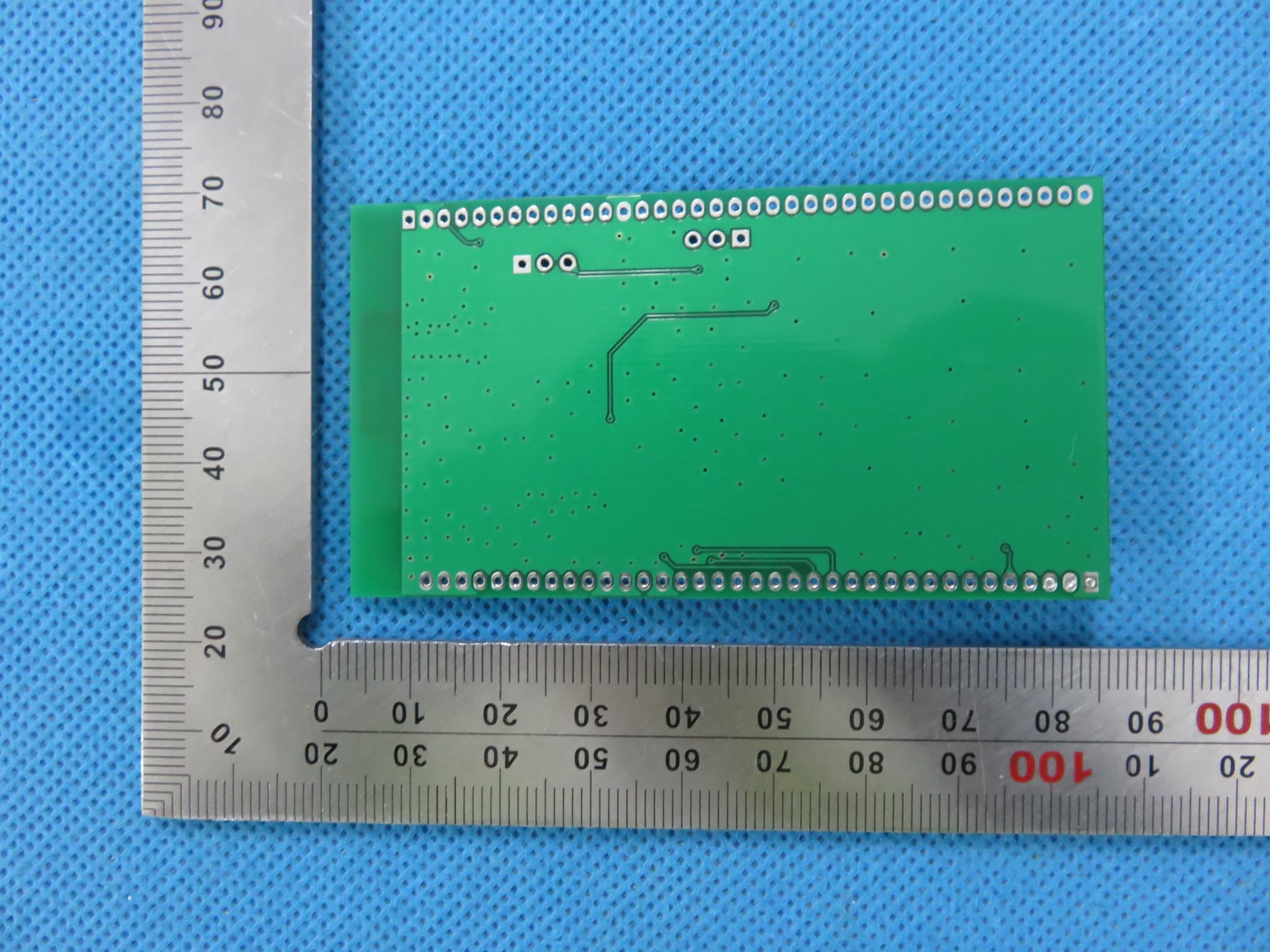
A5LCPR9851S
Mar 12, 2015bluetooth module
Equipment Class
DSS - Part 15 Spread Spectrum Transmitter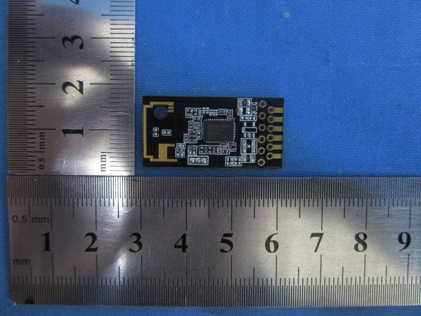
A5LRL-UM02
Jun 19, 2012RTL8188CTV WIFI module
Equipment Class
DTS - Digital Transmission System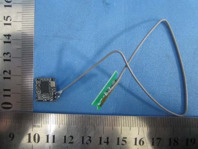
A5LRTL8188CUS
Jan 12, 2012RTL8188CUS WIFI module
Equipment Class
DTS - Digital Transmission System