A5MSWB100Lenovo Smartband
Lenovo (Beijing) Limited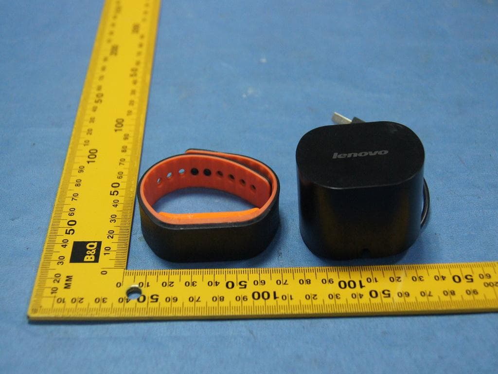
Click to zoom
Application Details
- Equipment Class
- DTS - Digital Transmission System
- Date of Grant
- Oct 03, 2014
- Application Purpose
- Original Equipment
- Date of Application
- Oct 03, 2014
- Equipment Note
- Lenovo Smartband
- Frequency Range
- 2402.00000000 - 2480.00000000
- Company
- Lenovo (Beijing) Limited
- Country
- China
Documents & Files
Document Text
Text extracted from the exhibit documents filed with the FCC. Open a document above to read the original.
Users Manual
LENOVO SMARTBAND Quick Start Basic operations Basic operations on the Smartband: Tap the screen once (hereinafter called tap) Tap the screen twice continuously (hereinafter called double-tap) The screen stays off when no operation is performed. When needed, double-tap to wake up the screen. By default, the following home screen is displayed when you wake up the screen. The home screen switches between the “time screen” and the “steps/calories screen”. Tap to toggle among the following screens: home, training mode, sleep mode, and heart-rate mode. Double-tapping on any of the mode screens will turn on or turn off the mode. Note: The “steps/calories” screen shows the real-time step count and calories of your daily activities. Function modes The Smartband provides three function modes: training mode, sleep mode, and heart-rate mode. Training mode You can set your training goals on the Smartband app, such as running time, distance, and calories. Turn on training mode when you start running, and the Smartband starts to record your workout data. With the ease of getting the time, distance, and calories data, your workout gets well under control. Related information or operations: On the training mode screen, double- tap to turn on training mode: After you enter training mode, the screen displays running time, distance, calories, and real-time heart rate in order. If you have set up a goal on the Smartband app, such as running time, this goal will be displayed in the first place. When you finish the workout, double- tap to exit training mode. Your workout data is saved. Sleep mode In sleep mode, Smartband helps you track your sleeping quality. You can turn on and turn off sleep mode by either operating on the Smartband or setting on the Smartband app. Related information or operations: Turning on sleep mode manually: On the sleep mode screen, double-tap to turn on sleep mode: Turn off sleep mode manually: Wake up the screen, on the following screen, double-tap to turn off sleep mode. Turning on or off sleep mode automatically: Set the starting and ending time for your sleep on the Smartband app. At the pre- set starting time, the Smartband enters sleep mode automatically. It vibrates and displays the following screen: At the pre-set ending time, the Smartband exits sleep mode automatically. It vibrates and displays the following screen: Double-tap, and the screen will display the total time of this sleep and show you the percentage of accomplishing your pre-set goal through a progress bar: Heart-rate mode You can ask the Smartband for your real- time heart rate. In addition, you can use the heart-rate data to control your training effect more precisely. Related information or operations: On the heart-rate mode screen, double-tap to enter heart-rate mode: Once in heart-rate mode, the Smartband starts to monitor your heart rate. During the process, the following screen is displayed: When the Smartband gets your heart- rate data, it vibrates and displays the data as follows: In the Smartband app, you can set upper and lower limits for your heart rate. In training mode, when your heart rate hits the upper or lower limit, the Smartband vibrates to help you control your training. Note: For accuracy of data, wear the Smartband tight enough to keep the heart-rate sensor closely against your skin. The sensor is located in the center on the bottom of the Smartband. Avoid any obstacle or scar between the heart-rate sensor and your skin. Heart-rate monitoring by the Smartband is for your personal reference only. Do not use it for medical purposes. Pairing To make full use of the Smartband functions, pair your Smartband with your smartphone or computer. To pair your Smartband with a device: 1. Ensure that your Smartband is not running in any function mode. 2. On the home screen, double-tap to display the following screen: “XXXX” represents the Smartband ID. 3. On your smartphone or computer, turn on Bluetooth and open the Smartband app, and select the Smartband you want to pair with. Then following the instructions on the device screen. Note: If pairing succeeds, the Smartband screen displays a “✓”. If pairing fails, the Smartband screen displays “X”. Reminder The Smartband provides multiple reminders, such as workout reminder, sleeping reminder, incoming call/SMS reminder, and custom reminder. On each type of reminder, the Smartband vibrates and displays text. Workout reminder If you do not meet your pre-set workout goal for three consecutive days, the Smartband will remind you with the following screen every morning at 9:00 am: Sleeping reminder If you do not meet your pre-set sleeping time goal for three consecutive days, the Smartband will remind you with the following screen every evening at 8:00 pm: Incoming call/SMS reminder If your smartphone is paired with your Smartband and has Bluetooth turned on, the Smartband will remind you when you receive an incoming call or an SMS. The Smartband will display the phone number of the incoming call or the SMS. If the phone number belongs to one of your phone contacts, the contact name will be displayed. Note: After you read the reminder, tap and the reminder will disappear. The reminder only shows the latest incoming call or SMS. The screen displays a maximum of 32 characters or 16 Chinese characters. Custom reminder You can set your custom reminder text and time in the Smartband app. Example: Data sync After you have paired your Smartband with your smartphone or computer, the Smartband will automatically sync with the Smartband app when you open the app. If the Smartband has entered a function mode, it does not affect the syncing. You can also click the sync button in the Smartband app to manually sync data anytime. During data syncing, the Smartband displays the following screen: When syncing is done, the home screen is displayed. Resetting the Smartband To reset the Smartband, do the following: 1. On the home screen, …
Text truncated - open the document above for the full version.
External Photos
Page 1 of 3 Type Designation: SW-B100 Report Number: 17042721 001 Fig. 1: External view Fig. 2: External view Page 2 of 3 Type Designation: SW-B100 Report Number: 17042721 001 Fig. 3: External view Fig. 4: External view Page 3 of 3 Type Designation: SW-B100 Report Number: 17042721 001 Fig. 5: External view
Internal Photos
Page 1 of 2 Type Designation: SW-B100 Report Number: 17042721 001 Fig. 1: Internal view Fig. 2: Internal view Page 2 of 2 Type Designation: SW-B100 Report Number: 17042721 001 Fig. 3: Internal view Fig. 4: Internal view
RF Exposure Info
Produkte Products RF Exposure Compliance Seite 1 von 1 Page 1 of 1 Product: Lenovo Smartband FCC ID: A5MSWB100 IC : 5903G-SWB100 Radio Frequency Exposure Compliance RESULT: Passed Test standard : RSS-102 Issue 4, March 2010 FCC KDB Publication 447498 D01 General RF Exposure Guidance v05r02 The minimum distance for the EUT is 5mm, since maximum peak output power of the transmitter is 1.8mW <10mW, hence the EUT is exclueded from SAR evaluation according to FCC KDB publication 447498 D01: Mobile and Portable RF Exposure.Guidance v05. The maximum peak output power of the transmitter is 1.8mW only, which less than 20mW. Hence the EUT is exempted from routine evaluation limits (SAR Evaluation) according to clause 2.5.1 of RSS-102 Issue 4.
Test Report
Produkte Products Appendix 1 17042721 001 Page 3 of 32 Figure 3: Test figure of spurious emissions, mode A.1, Horizontal polarity (30MHz – 1GHz) Produkte Products Appendix 1 17042721 001 Page 4 of 32 Figure 4: Test figure of spurious emissions, mode A.1, Vertical polarity (30MHz – 1GHz) Produkte Products Appendix 1 17042721 001 Page 5 of 32 Figure 5: Test figure of spurious emissions, mode A.1, Horizontal polarity (1GHz –18GHz) Produkte Products Appendix 1 17042721 001 Page 6 of 32 Figure 6: Test figure of spurious emissions, mode A.1, Vertical polarity (1GHz – 18GHz) Produkte Products Appendix 1 17042721 001 Page 7 of 32 Figure 7: Test figure of spurious emissions, mode A.1, Horizontal polarity (18GHz –25GHz) Produkte Products Appendix 1 17042721 001 Page 8 of 32 Figure 8: Test figure of spurious emissions, mode A.1, Vertical polarity (18GHz – 25GHz) Produkte Products Appendix 1 17042721 001 Page 9 of 32 Figure 9: Test figure of spurious emissions, mode A.2, Horizontal polarity (9kHz – 30MHz) Figure 10: Test figure of spurious emissions, mode A.2, Vertical polarity (9kHz – 30MHz) Produkte Products Appendix 1 17042721 001 Page 10 of 32 Figure 11: Test figure of spurious emissions, mode A.2, Horizontal polarity (30MHz – 1GHz) Produkte Products Appendix 1 17042721 001 Page 11 of 32 Figure 12: Test figure of spurious emissions, mode A.2, Vertical polarity (30MHz – 1GHz) Produkte Products Appendix 1 17042721 001 Page 12 of 32 Figure 13: Test figure of spurious emissions, mode A.2, Horizontal polarity (1GHz – 18GHz) Produkte Products Appendix 1 17042721 001 Page 13 of 32 Figure 14: Test figure of spurious emissions, mode A.2, Vertical polarity (1GHz – 18GHz) Produkte Products Appendix 1 17042721 001 Page 14 of 32 Figure 15: Test figure of spurious emissions, mode A.2, Horizontal polarity (18GHz – 25GHz) Produkte Products Appendix 1 17042721 001 Page 15 of 32 Figure 16: Test figure of spurious emissions, mode A.2, Vertical polarity (18GHz – 25GHz) Produkte Products Appendix 1 17042721 001 Page 16 of 32 Figure 17: Test figure of spurious emissions, mode A.3, Horizontal polarity (9kHz – 30MHz) Figure 18: Test figure of spurious emissions, mode A.3, Vertical polarity (9kHz – 30MHz) Produkte Products Appendix 1 17042721 001 Page 17 of 32 Figure 19: Test figure of spurious emissions, mode A.3, Horizontal polarity (30MHz – 1GHz) Produkte Products Appendix 1 17042721 001 Page 18 of 32 Figure 20: Test figure of spurious emissions, mode A.3, Vertical polarity (30MHz – 1GHz) Produkte Products Appendix 1 17042721 001 Page 19 of 32 Figure 21: Test figure of spurious emissions, mode A.3, Horizontal polarity (1GHz –18GHz) Produkte Products Appendix 1 17042721 001 Page 20 of 32 Figure 22: Test figure of spurious emissions, mode A.3, Vertical polarity (1GHz – 18GHz) Produkte Products Appendix 1 17042721 001 Page 21 of 32 Figure 23: Test figure of spurious emissions, mode A.3, Horizontal polarity (18GHz –25GHz) Produkte Products Appendix 1 17042721 001 Page 22 of 32 Figure 24: Test figure of spurious emissions, mode A.3, Vertical polarity (18GHz – 25GHz) Produkte Products Appendix 1 17042721 001 Page 23 of 32 Figure 25: Test figure of Radiated emissions in restricted bands, Mode A.1, Horizontal Produkte Products Appendix 1 17042721 001 Page 24 of 32 Figure 26: Test figure of Radiated emissions in restricted bands, Mode A.1, Vertical Produkte Products Appendix 1 17042721 001 Page 25 of 32 Figure 27: Test figure of Radiated emissions in restricted bands, Mode A.3, Horizontal Produkte Products Appendix 1 17042721 001 Page 26 of 32 Figure 28: Test figure of Radiated emissions in restricted bands, Mode A.3, Vertical Produkte Products Appendix 1 17042721 001 Page 27 of 32 Figure 29: Test figure of Conducted emissions, Mode B, line live Produkte Products Appendix 1 17042721 001 Page 28 of 32 Figure 30: Test figure of Conducted emissions, Mode B, line neutral Produkte Products Appendix 1 17042721 001 Page 29 of 32 Figure 31: Test figure of Radiated emissions, Mode B, Below 1GHz, Horizontal Produkte Products Appendix 1 17042721 001 Page 30 of 32 Figure 32: Test figure of Radiated emissions, Mode B, Below 1GHz, Vertical Produkte Products Appendix 1 17042721 001 Page 31 of 32 Figure 33: Test figure of Radiated emissions, Mode B, Above 1GHz, Horizontal Produkte Products Appendix 1 17042721 001 Page 32 of 32 Figure 34: Test figure of Radiated emissions, Mode B, Above 1GHz, Vertical
Test Report
Produkte Products Prüfbericht - Nr.: Test Report No. 17042721 001 Seite 2 von 28 Page 2 of 28 TEST SUMMARY 5.1.1 ANTENNA REQUIREMENT RESULT: Passed 5.1.2 PEAK OUTPUT POWER RESULT: Passed 5.1.3 CONDUCTED POWER SPECTRAL DENSITY RESULT: Passed 5.1.4 -6DB BANDWIDTH RESULT: Passed 5.1.5 99% BANDWIDTH RESULT: Passed 5.1.6 CONDUCTED SPURIOUS EMISSIONS MEASURED IN 100KHZ BANDWIDTH RESULT: Passed 5.1.7 SPURIOUS EMISSION RESULT: Passed 5.1.8 CONDUCTED EMISSIONS RESULT: Passed 5.1.9 RADIATED EMISSION RESULT: Passed Produkte Products Prüfbericht - Nr.: Test Report No. 17042721 001 Seite 3 von 28 Page 3 of 28 Contents 1. GENERAL REMARKS ......................................................................................................... 4 1.1 COMPLEMENTARY MATERIALS .......................................................................................... 4 2. TEST SITES ...................................................................................................................... 4 2.1 TEST FACILITIES ............................................................................................................... 4 2.2 LIST OF TEST AND MEASUREMENT INSTRUMENTS ............................................................... 5 2.3 T RACEABILITY .................................................................................................................. 6 2.4 CALIBRATION ................................................................................................................... 6 2.5 MEASUREMENT UNCERTAINTY........................................................................................... 6 2.6 LOCATION OF ORIGINAL DATA ........................................................................................... 6 2.7 STATUS OF FACILITY USED FOR TESTING ........................................................................... 6 3. G ENERAL PRODUCT INFORMATION .................................................................................... 7 3.1 PRODUCT FUNCTION AND INTENDED USE ........................................................................... 7 3.2 RATINGS AND SYSTEM DETAILS ........................................................................................ 7 3.3 I NDEPENDENT OPERATION MODES .................................................................................... 8 3.4 NOISE GENERATING AND NOISE SUPPRESSING PARTS ....................................................... 8 3.5 SUBMITTED DOCUMENTS .................................................................................................. 8 4. T EST SET-UP AND OPERATION MODES .............................................................................. 9 4.1 PRINCIPLE OF CONFIGURATION SELECTION ........................................................................ 9 4.2 TEST OPERATION AND TEST SOFTWARE ............................................................................ 9 4.3 S PECIAL ACCESSORIES AND AUXILIARY EQUIPMENT .......................................................... 9 4.4 COUNTERMEASURES TO ACHIEVE EMC COMPLIANCE ....................................................... 10 4.5 TEST SETUP DIAGRAM .................................................................................................... 10 5. T EST RESULTS ............................................................................................................... 12 5.1 TRANSMITTER REQUIREMENT & TEST SUITES .................................................................. 12 5.1.1 Antenna Requirement ................................................................................................................ 12 5.1.2 Peak Output Power .................................................................................................................... 13 5.1.3 Conducted Power Spectral Density ........................................................................................... 14 5.1.4 -6dB Bandwidth .......................................................................................................................... 15 5.1.5 99% Bandwidth .......................................................................................................................... 16 5.1.6 Conducted spurious emissions measured in 100kHz Bandwidth .............................................. 17 5.1.7 Spurious Emission ..................................................................................................................... 21 5.1.8 Conducted emissions ................................................................................................................. 22 5.1.9 Radiated Emission ..................................................................................................................... 23 6. P HOTOGRAPHS OF THE TEST SET-UP .............................................................................. 24 7. L IST OF TABLES ............................................................................................................. 28 8. LIST OF PHOTOGRAPHS .................................................................................................. 28 Produkte Products Prüfbericht - Nr.: Test Report No. 17042721 001 Seite 4 von 28 Page 4 of 28 1. General Remarks 1.1 Complementary Materials All attachments are integral parts of this test report. This applies especially to the following appendix: Appendix 1: Test Result 2. Test Sites 2.1 Test Facilities Shenzhen Accurate Technology Co., Ltd. F1, Bldg. A, Changyuan New Meterial Port, Keyuan Rd., Science & Industry Park Nanshan District, Shenzhen 518057, P.R. China FCC Registration No.: 752051 The tests at the test site have been conducted under the supervision of a TÜV engineer. Produkte Products Prüfbericht - Nr.: Test Report No. 17042721 001 Seite 5 von 28 Page 5 of 28 2.2 List of Test and Measurement Instruments Table 1: List of Test and Measurement Equipment Kind of Equipment Manufacturer Type S/N Calibrated until Spurious emission a…
Text truncated - open the document above for the full version.
Test Setup Photos
Produkte Products Prüfbericht - Nr.: Test Report No. 17042721 001 Seite 24 von 28 Page 24 of 28 6. Photographs of the Test Set-Up Photograph 1: Set-up for Spurious Emissions (9kHz-30MHz) Photograph 2: Set-up for Spurious Emissions (30MHz-1GHz) Produkte Products Prüfbericht - Nr.: Test Report No. 17042721 001 Seite 25 von 28 Page 25 of 28 Photograph 3: Set-up for Spurious Emissions (1GHz-18GHz) Photograph 4: Set-up for Spurious Emissions (18GHz-26GHz) Produkte Products Prüfbericht - Nr.: Test Report No. 17042721 001 Seite 26 von 28 Page 26 of 28 Photograph 5: Set-up for Conducted Emissions Photograph 6: Set-up for Radiated Emissions, below 1GHz Produkte Products Prüfbericht - Nr.: Test Report No. 17042721 001 Seite 27 von 28 Page 27 of 28 Photograph 7: Set-up for Radiated Emissions, above 1GHz
Contact Information
Applicant
Yang Liu(Compliance Engineer)
Test Firm
Accurate Technology Co., Ltd.Sean Liu
Technical Specifications
| # | Rule Parts | Frequency Range | Power Output |
|---|---|---|---|
| 1 | 15C | 2.40 GHz - 2.48 GHz | 1.79 mW |
Other Applications from Lenovo (Beijing) Limited
A5MH50
Aug 21, 2026TALIX H50 Noise Cancelling Over-ear Headphones
Equipment Class
DTS - Digital Transmission SystemA5MWT1206
Jul 30, 2026wegear T10 True Wireless Earbuds
Equipment Class
DSS - Part 15 Spread Spectrum Transmitter
A5M-M830
Jul 16, 2026Lenovo Al Mouse
Equipment Class
DTS - Digital Transmission System
A5M-SE01
Jul 07, 2026Lenovo Pen Pro for Googlebook
Equipment Class
DTS - Digital Transmission System
A5M-GK470
Jun 08, 2026wegear BLITZ B79 Wireless Mechanical Gaming Keyboard
Equipment Class
DSS - Part 15 Spread Spectrum Transmitter