A7AR2500NTotal Station
TI Asahi Co., Ltd.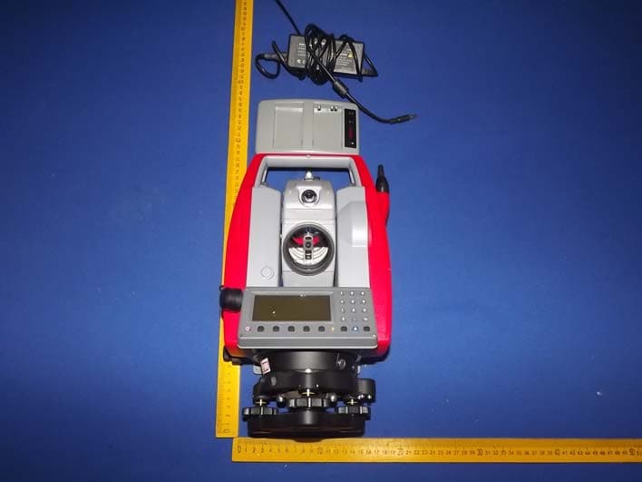
Click to zoom
Application Details
- Equipment Class
- DSS - Part 15 Spread Spectrum Transmitter
- Date of Grant
- May 13, 2014
- Application Purpose
- Original Equipment
- Date of Application
- May 13, 2014
- Equipment Note
- Total Station
- Frequency Range
- 2402.00000000 - 2480.00000000
- Company
- TI Asahi Co., Ltd.
- Country
- Japan
Documents & Files
Document Text
Text extracted from the exhibit documents filed with the FCC. Open a document above to read the original.
Users Manual
TOTAL STATION R-2500DNSERIES R-2501DN,R-2502DN R-2503DN,R-2505DN INSTRUCTION MANUAL Basic Procedures TI Asahi Co.,Ltd. International Sales Department 4-3-4 Ueno Iwatsuki-Ku,Saitama-Si Saitama,339-0073 Japan Tel, +81-48-793-0118 Fax, +81-48-793-0128 E-mail : [email protected] PENTAX Ⓡ CONTENTS General CONTENTS Exemption clause Copyright PRECAUTIONS REGARDING SAFETY Warning Usage Precautions 1 4 4 5 5 8 1. BASIC OPERATION 1.1 Names of parts 1.2 Standard equipment 1.3 Unpacking and packing 1.4 Removing and attaching the Battery 1.5 How to charge the Battery 1.6 Inserting and Removing of various SD cards 1.6.1 Inserting SD card 11 11 12 12 12 13 16 16 16 17 18 18 19 19 19 20 21 22 22 23 1.6.2 Removing SD card 1.6.3 Inserting SD card for camera data 1.6.4 Removing SD card for camera data 1.6.5 Suitability of SD card 1.7 Inserting and Removing of various USB cables 1.7.1 Connecting USB cable 1.7.2 Removing USB cable 1.7.3 Inserting USB cable for camera data 1.7.4 Removing USB cable for camera data 1.8 About recorded data 1.8.1 About measure data 1.8.2 About photography data 2. DISPLAY AND KEYBOARD 2.1 Display and keyboard 2.2 Operation key 2.3 Function Key 2.4 Alphanumeric input 2.5 Laser pointer 25 25 25 26 30 30 3. PREPARATION FOR SURVEYING 3.1 Centring and Levelling of the Instrument 3.2 Laser plummet 3.3 Levelling with circular vial 3.4 Levelling with the plate vial 3.5 Eyepiece adjustment 31 31 31 33 33 33 34 34 3.6 Target sighting 3.7 Attachment and detachment of tribrach 4. TURNING THE POWER ON 4.1 Turning the power on and off 4.2 Adjusting LCD contrast 36 36 36 1 4.3 Adjusting illumination brightness 4.4 Adjusting reticle illumination 37 37 5. ANGLE MEASUREMENT 5.1 Measuring an angle 38 38 38 39 39 40 41 5.2 Resetting the horizontal angle to 0 5.3 Holding the horizontal angle 5.4 Inputting an arbitrary horizontal angle 5.5 Displaying the % slope of the vertical angle 5.6 Changing the horizontal angle from clockwise to counter clockwise 6. DISTANCE MEASUREMENT 6.1 Target setting 6.2 Distance measurement 6.3 Quick Mode 42 42 43 44 7. CORRECTION MODE 45 45 46 47 48 7.1 Changing the target constant 7.2 Changing the temperature 7.3 Changing the atmospheric pressure 7.4 Changing the ppm value 8. INITIAL SETTING 8.1 Overview 49 49 49 49 49 50 50 50 8.2 Entering the mode for initial setting 1 8.3 Entering the mode for initial setting 2 8.4 Entering the mode for initial setting 3 8.5 Entering the mode for initial setting 4 8.6 Entering the mode for initial setting 5 8.7 Entering the mode for setting of data and time 8.8 Example of changing an initial setting content (selection of atmospheric correction) 8.9 Initial setting 1 8.10 Initial setting 2 8.11 Initial setting 3 8.12 Initial setting 4 8.13 Initial setting 5 51 52 53 55 55 55 56 8.14 Setting of date and time 9. ACCESSING THE FUNCTIONS 9.1 Accessing by help key 9.2 Accessing by 007 57 57 57 10. DIGITAL CAMERA 10.1 Turning the camera On and Off 10.2 Taking pictures 59 59 60 60 61 62 10.2.1 Taking pictures and measuring distance at the same time 10.2.2 10.2.3 Taking pictures without measuring distance Zooming 2 15. FCC RELATED 100 15.1 FCC Statement 100 15.2 FCC radiation exposure statement 100 10.3 Slide Show 10.4 Playing back images 63 64 64 64 65 66 66 67 67 68 69 75 77 10.4.1 10.4.2 Rotating images Searching images 10.4.3 Deleting images 10.4.4 10.4.5 10.4.6 Adding PointCode to images Displaying measured data Zooming images 10.4.7 Moving images 10.5 Setup 10.6 Adjusting the camera settings 10.7 Adjusting Point Mark position 10.8 Correct Center Mode 11. DATA COLLECTOR 80 12. CHECKS AND ADJUSTMENTS 12.1 Plate level 12.2 Circular vial 80 80 81 82 83 84 84 84 85 86 12.3 Vertical reticle 12.4 Perpendicularity of line of sight to horizontal axis 12.5 Vertical 0 point error 12.6 Optical plummet 12.7 Offset constant 12.8 Beam axis and line of sight 12.9 The EDM beam axis 13. APPENDIX 13.1 Warning and Error Messages 13.2 Atmospheric correction 13.3 hPa and mmHg conversion table 13.4 Error when no atmospheric correction is made 13.5 Atmospheric refraction and earth curvature correction 13.6 Distance range 87 87 88 88 89 90 91 92 13.7 Specifications 14. NOTICE TO THE USER OF THIS PRODUCT 14.1 Specifications of Laser Radiation 96 96 14.2 The following labels are affixed to and must remain attached to this laser product. 14.3 Caution to maintain the safety in compliance with the standard 14.4 Labelling 96 97 98 3 4 Before using this product, be sure that you have thoroughly read and understood this instruction manual to ensure proper operation. After reading this manual, be sure to keep in a convenient place for easy reference. Exemption clause 1) TI Asahi Co.,Ltd. (TIA) shall not be liable for damage caused by Acts of God, fire, alteration or servicing by unauthorized parties, accident, negligence, misuse, abnormal operating conditions. 2) TIA shall not be liable for changes or disappearance of data, loss of company profit or interruption of company operation incurred by the use of this product or malfunction of it. 3) TIA shall not be liable for damage caused by usage not explained in the instruction manual. 4) TIA shall not be liable for damage to this product caused by other equipment connected to this product. Copyright © 2013 TI Asahi Co.,Ltd. All Rights Reserved TI Asahi Co.,Ltd. is a sole proprietor of the PowerTopoLite software. The PowerTopoLite software and publication or parts thereof, may not be reproduced in any form, by any method, for any purpose. TI Asahi Co.,Ltd. makes no warranty, expressed or implied, including but not limited to any implied warranties or merchantability or fitness for a particular purpose, regarding these materials and makes such materials available. 5 PRECAUTIONS REGARDING SAFETYxxxx xxxxxxxxx Safety precautions (Must be followed) The following items are intended to prevent possible injury to the user or other people and/or damage to the instrument before it occurs. These safety precautions are importan…
Text truncated - open the document above for the full version.
Cover Letter(s)
TI Asahi Co., Ltd. FCC Confidentiality Request Number: CF303 Version: V05 Date: 21-05-2012 (Permanent or also called long term confidentiality is the normal method to keep certain docuements confidential, and may apply to schematics, block diagrams, operational description and bill of materials.) To: Federal Communications Commission Equipment Authorization Branch 7435 Oakland Mills Road Columbia, MD 21046 Pursuant to 47 CFR Section 0.459(a) & (b), we, (the applicant / grantee) Company name TI Asahi Co., Ltd. Address 4-3-4 Ueno, Iwatsuki-ku, Saitama-shi, City Saitama Country Japan request for this certification filing under: Grantee Code Product Number FCC ID: A7A R2500N to maintain permanent confidentiality for the following documents submitted within this application: (please cross what is applicable, or add other documents, provide the file name and description) Exhibit File Name Description √ Operational Description Operational Description explaining the functioning of the block diagram √ Block Diagrams Block Diagrams showing the systematic building blocks of the EUT √ Schematics Diagrams Schematics showing components, their values and interconnection Bill of Materials List of components used on the PCB’s of the EUT Above materials crossed contain secrets, proprietary and technical information, which would customarily be guarded from competitors under 47 CFR, section 0.457(d)(2). Disclosure or publication or any portion of this company confidential material to other parties could cause substantial competitive harm and provide unjustified benefits for competitors. We understand that pursuant to 47 CFR section 0.457(d)(1)(ii) disclosure of the applicant and all accompanying documentation will not be made before the date of the grant. The documents indicated as confidential above, are not publicly available elsewhere. Attestation: City and Country: Date: Name: (this must be a person) Function:Signature: (or official company stamp) Saitama, Japan 2014-05-09 Mikio HorieEngineer
External Photos
Figure 1 The EUT-Overall View Figure 2 The EUT-Front View Figure 3 The EUT-Back View
ID Label/Location Info
Label Location On EUT
ID Label/Location Info
TI Asahi Co., Ltd.
Internal Photos
Figure 4 The EUT-Inside View Figure 5 PCB of the EUT-Front View Figure 6 PCB of the EUT-Back View Figure 7 PCB of the EUT-Front View Figure 8 PCB of the EUT-Back View Figure 9 PCB of the EUT-Front View Figure 10 PCB of the EUT-Back View Figure 11 PCB of the EUT-Front View Figure 12 PCB of the EUT-Back View Figure 13 PCB of the BT Module View
RF Exposure Info
MPE Calculation FCC ID: A7AR2500N EUT Description: Total Station Typical use distance: d ≥ 20 cm Power density limit for mobile devices at 2.4GHz: S ≤ 1 mW/cm 2 Remark: Average ≤ Peak, which means that calculating the power density applying Peak power is worst case. The worst case operation mode generating the highest power in each frequency range is taken for calculation. Frequency range: 2402-2480 MHz (BT) Maximum measured conducted power (Peak): P conducted = 1.21 dBm = 1.33 mW Antenna Gain: G = 1 dBi Calculation: P radiated = P conducted + G linear = 1.21 dBm + 1 dBi = 2.21 dBm = 1.66 mW Power density S = (P radiated ) / (4π x d 2 ) = 1.66 / 5026 =0.00033 mW/cm 2 is below the limit, so pass.
Test Report
Shenzhen Anbotek Compliance Laboratory Limited FCC ID: A7AR2500N Page 1 of 58 Report No. 201307922F Shenzhen Anbotek Compliance Laboratory Limited Tel: (86)755-26066544 Fax: (86)755-26014772 www.anbotek.com FCC TEST REPORT for TI Asahi Co., Ltd. Total Station Model No.: R-2501N, R-2502N, R-2503N, R-2505N, R-2501DN, R-2502DN, R-2503DN, R-2505DN Prepared for : TI Asahi Co., Ltd. Address : 4-3-4 Ueno, Iwatsuki-ku, Saitama-shi, Saitama, 339-0073, Japan Prepared By : Shenzhen Anbotek Compliance Laboratory Limited Address : 1/F., Building 1, SEC Industrial Park, No.0409 Qianhai Road, Nanshan District, Shenzhen, Guangdong, China Tel: (86) 755-26066544 Fax: (86) 755-26014772 Report Number : 201307922F Date of Test : Oct. 09, 2013~ Mar. 30, 2014 Date of Report : Apr. 02, 2014 Shenzhen Anbotek Compliance Laboratory Limited FCC ID: A7AR2500N Page 2 of 58 Report No. 201307922F Shenzhen Anbotek Compliance Laboratory Limited Tel: (86)755-26066544 Fax: (86)755-26014772 www.anbotek.com TABLE OF CONTENTS Description Page Test Report 1. GENERAL INFORMATION ......................................................................................................... 5 1.1. Description of Device (EUT) .................................................................................................................... 5 1.2. Auxiliary Equipment Used during Test .................................................................................................... 6 1.3. Description of Test Facility ...................................................................................................................... 6 1.4. Measurement Uncertainty ......................................................................................................................... 6 2. TEST PROCEDURE ....................................................................................................................... 7 3. CONDUCTED LIMITS .................................................................................................................. 8 3.1. Block Diagram of Test Setup ................................................................................................................... 8 3.2. Power Line Conducted Emission Measurement Limits (15.207) ............................................................. 8 3.3. Configuration of EUT on Measurement ................................................................................................... 8 3.4. Operating Condition of EUT .................................................................................................................... 8 3.5. Test Procedure .......................................................................................................................................... 9 3.6. Power Line Conducted Emission Measurement Results .......................................................................... 9 4. RADIATION INTERFERENCE .................................................................................................. 12 4.2. Test Procedure ........................................................................................................................................ 12 4.3. Test Configuration: ................................................................................................................................. 13 4.4. Test Results ............................................................................................................................................. 14 5. CHANNEL SEPARATION TEST ............................................................................................... 25 5.1. Measurement Procedure ......................................................................................................................... 25 5.2. Test SET-UP ........................................................................................................................................... 25 5.3. Test Equipment ....................................................................................................................................... 25 5.4. Test Results ............................................................................................................................................. 26 6. 20DB BANDWIDTH TEST .......................................................................................................... 30 6.1. Measurement Procedure ......................................................................................................................... 30 6.2. Test SET-UP ........................................................................................................................................... 30 6.3. Test Equipment ....................................................................................................................................... 30 6.4. Test Results ............................................................................................................................................. 31 7. QUANTITY OF HOPPING CHANNEL TEST .......................................................................... 35 7.1. Measurement Procedure ......................................................................................................................... 35 7.2. Test SET-UP ........................................................................................................................................... 35 7.3. Test Equipment ....................................................................................................................................... 35 7.4. Test Results ............................................................................................................................................. 35 8. DWELL TIME TEST .................................................................................................................... 37 8.1. Measurement Procedure ........................................…
Text truncated - open the document above for the full version.
Test Setup Photos
1. Photo of Power Line Conducted Emission Test 2.Photo of Radiated Emission Test
Contact Information
Applicant
Mikio Horie(Emplyee)
Technical Contact
Test Firm
Shenzhen Anbotek Compliance Laboratory LimitedDaniel zhu
[email protected]86-755-26014771
Technical Specifications
| # | Rule Parts | Frequency Range | Power Output |
|---|---|---|---|
| 1 | 15C | 2.40 GHz - 2.48 GHz | 1.33 mW |
Other Applications from TI Asahi Co., Ltd.
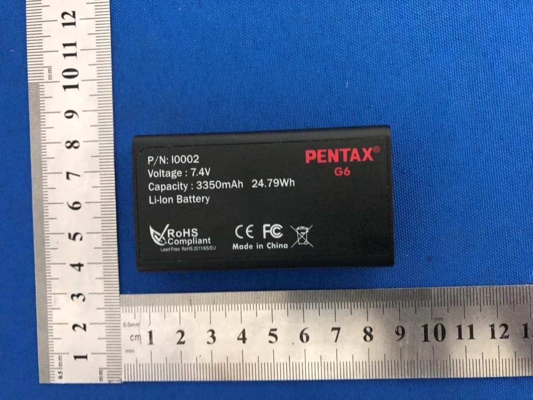
A7AG6NA
Mar 08, 2021GNSS Receiver
Equipment Class
DSS - Part 15 Spread Spectrum Transmitter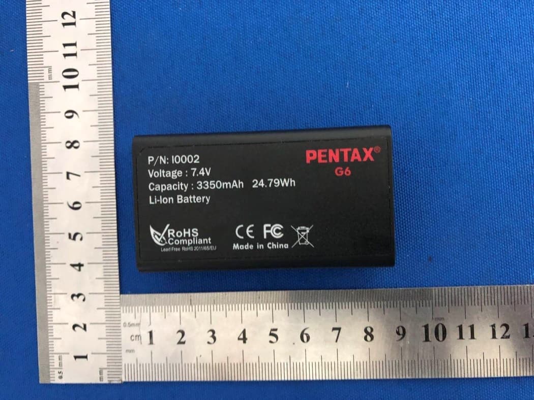
A7AG6TA
Mar 07, 2021GNSS Receiver
Equipment Class
DTS - Digital Transmission System
A7AG3100-R2
Dec 22, 2014GNSS receiver
Equipment Class
DXT - Part 15 Low Power Transceiver, Rx Verified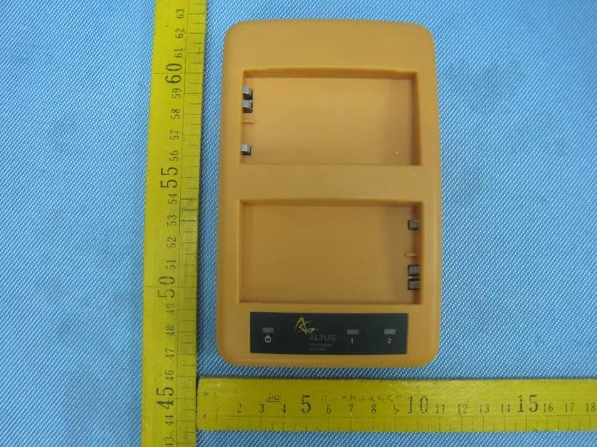
A7AG2100B
Dec 19, 2012GNSS
Equipment Class
JBP - Part 15 Class B Computing Device Peripheral
A7AG3100-R1
Jul 08, 2012GNSS
Equipment Class
JBP - Part 15 Class B Computing Device Peripheral