A7C-GB8000F-000802.11b/g/a/n Wireless Access Point
GoNet Systems Ltd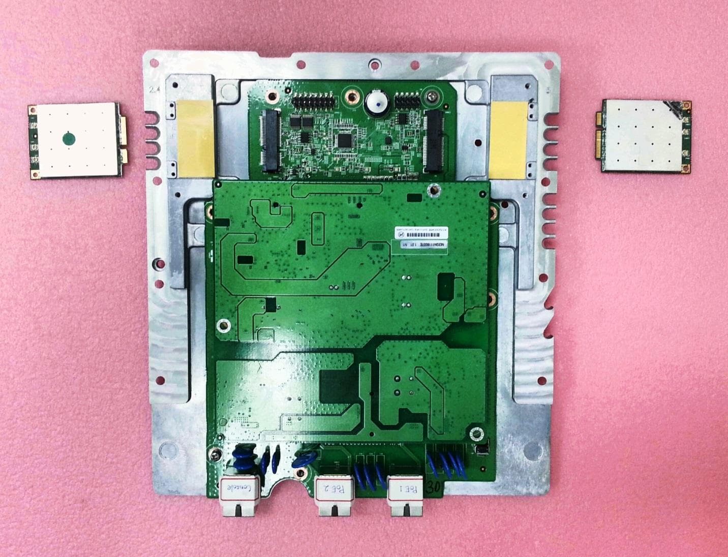
Click to zoom
Application Details
- Equipment Class
- DTS - Digital Transmission System
- Date of Grant
- Mar 31, 2014
- Application Purpose
- Original Equipment
- Date of Application
- Mar 27, 2014
- Equipment Note
- 802.11b/g/a/n Wireless Access Point
- Frequency Range
- 5755.00000000 - 5795.00000000
- Company
- GoNet Systems Ltd
- Country
- Israel
Documents & Files
Document Text
Text extracted from the exhibit documents filed with the FCC. Open a document above to read the original.
Users Manual
Proprietary Information - Confidential DO001152 GoBeam-8000 Assembly Instruction Revision: 1.1 Page: 1 out of 16 Approval Date: 16.12.2013 Effective Date: 16.12.2013 Update by: Approved by: Oleg Einem Nimrod Tenne Sharon Ashkenazi Page 1 of 16 DO001152 REV 1.1 Printed version are uncontrolled Revision History Revision Date Changes Modified By Approved By 1.0 09.12.13 Release Work Procedure Oleg Einem Nimrod Tenne 1.1 06.01.14 Fixed Oleg Einem Sharon Ashkenazi Proprietary Information - Confidential DO001152 GoBeam-8000 Assembly Instruction Revision: 1.1 Page: 2 out of 16 Approval Date: 16.12.2013 Effective Date: 16.12.2013 Update by: Approved by: Oleg Einem Nimrod Tenne Sharon Ashkenazi Page 2 of 16 DO001152 REV 1.1 Printed version are uncontrolled Table of Content Revision History ................................................................................................................................ 1 1. Introduction ................................................................................................................................ 3 2. Required Tools ........................................................................................................................... 3 3. General Instructions ................................................................................................................... 3 4. Mechanical Assembly ................................................................................................................ 4 4.1. Heat Conductive Gap Fillers Gluing 4 4.2. Light pipes 5 4.3. Sealing Gasket. 5 4.4. Adhesive Membrane Vent Gluing 6 4.5. CPU board. 6 4.6. PS board. 7 4.7. Wireless mini PCI Boards 2.4GHz, 5GHz. 8 4.8. Mechanical Assembly. 10 4.9. Beam Forming. 11 4.10. Antennas. 13 4.11. Radom. 14 4.12. Sealing screw. 15 4.13. Ground Screw 15 4.14. Plug for ETH2 16 4.15. Labels Sticking 16 Proprietary Information - Confidential DO001152 GoBeam-8000 Assembly Instruction Revision: 1.1 Page: 3 out of 16 Approval Date: 16.12.2013 Effective Date: 16.12.2013 Update by: Approved by: Oleg Einem Nimrod Tenne Sharon Ashkenazi Page 3 of 16 DO001152 REV 1.1 Printed version are uncontrolled 1. Introduction This document describes in detail the assembly process of the GoBeam-8000 Top level Systems. 2. Required Tools Automatic screw drivers with torque (for example “Delvo” DLV-7333 and DLV-7140). Philips screw head bits size 1 and 2. Hexagon head bit size 5mm. PLCC Instructor. 3. General Instructions 3.1. Before assembling verify that all required items are in following conditions: 3.1.1. Parts are in correspondence with proper part numbers and revisions. 3.1.2. All items are in good condition, not damaged and fully clean. 3.1.3. Each component has relevant certificate, test report and approval. 3.1.4. Tools are calibrated, tested in time and approved for use. 3.1.5. Working place is properly equipped, clean and free of extraneous objects. 3.2. All assembly executors must carefully follow these instructions. 3.3. Unless otherwise specified use Soudure NET 9418 (Go P/n: MS000010) for cleaning and degreasing. 3.4. Unless otherwise specified screws bit size and closing torque should be in accordance with the following table: Screw Size M2 M3 M3 Nylon M4 M5 Bit size 1 2 Required Torque 4 kg-cm 3.5 lb-In 6.9 kg-cm 6 lb-In 3.5 kg-cm 3 lb-In 17 kg-cm 14.8 lb-In 30 kg-cm 26 lb-In Proprietary Information - Confidential DO001152 GoBeam-8000 Assembly Instruction Revision: 1.1 Page: 4 out of 16 Approval Date: 16.12.2013 Effective Date: 16.12.2013 Update by: Approved by: Oleg Einem Nimrod Tenne Sharon Ashkenazi Page 4 of 16 DO001152 REV 1.1 Printed version are uncontrolled 4. Mechanical Assembly 4.1. Heat Conductive Gap Fillers Gluing 4.1.1. Stick items 2...6 to item 1 after previously cleaning related surfaces of item 1. Item Description Part No QTY 1 Base MC000471 1 2 Thermal Pad 50x25x2 mm MC000500 2 3 Thermal PAD(45*7*1t) MC000477 1 4 Thermal PAD(26*26*1t) MC000478 1 5 Thermal PAD(7.5*6.5*1t) MC000479 4 6 Thermal PAD(8*8*1t) MC000480 2 Proprietary Information - Confidential DO001152 GoBeam-8000 Assembly Instruction Revision: 1.1 Page: 5 out of 16 Approval Date: 16.12.2013 Effective Date: 16.12.2013 Update by: Approved by: Oleg Einem Nimrod Tenne Sharon Ashkenazi Page 5 of 16 DO001152 REV 1.1 Printed version are uncontrolled 4.2. Light pipes 4.2.1. Paste the light pipes (item 3) to the item 1 by item 2 without holes between body and light pipes. 4.3. Sealing Gasket. Fit the Sealing Gasket (item 2) into the Body’s groove after previously applying Grease MS000008. Ensure that the gasket seats proper along the groove and any of its particles do not get out. Item Description Part No QTY 1 Base MC000471 1 2 Silicon MS000022 0.08mL 3 Light Pipe MC000483 1 Item Description Part No QTY 1 Base MC000471 1 2 O-Ring MC000495 1 Proprietary Information - Confidential DO001152 GoBeam-8000 Assembly Instruction Revision: 1.1 Page: 6 out of 16 Approval Date: 16.12.2013 Effective Date: 16.12.2013 Update by: Approved by: Oleg Einem Nimrod Tenne Sharon Ashkenazi Page 6 of 16 DO001152 REV 1.1 Printed version are uncontrolled 4.4. Adhesive Membrane Vent Gluing Stick item 2 to item 1 after previously cleaning related surface of item 1. 4.5. CPU board. 4.5.1. Stick items 2, 3 to item 1 after previously cleaning related surfaces of item 1. Item Description Part No QTY 1 Base MC000471 1 2 Adhesive Membrane Vent MC000030 1 Item Description Part No QTY 1 PCB Holder MC000472 1 2 Thermal PAD(38*18*1t) MC000475 2 3 Thermal PAD(67*100*1t) MC000476 1 1 2 Proprietary Information - Confidential DO001152 GoBeam-8000 Assembly Instruction Revision: 1.1 Page: 7 out of 16 Approval Date: 16.12.2013 Effective Date: 16.12.2013 Update by: Approved by: Oleg Einem Nimrod Tenne Sharon Ashkenazi Page 7 of 16 DO001152 REV 1.1 Printed version are uncontrolled 4.5.2. Connect item 2 to item 1 and fasten it by item 3 and item 4 as shown in the image. 4.6. PS board. 4.6.1. Connect item 2 to item 1 and fa…
Text truncated - open the document above for the full version.
Users Manual
All contents are Copyright © 2013 Go Net Systems Ltd. All rights reserved. Document# GoBeam8000 Quick Configuration Guide All contents are Copyright © 2013 GO Net Systems Ltd. All rights reserved. Document# GoBeam 5100/6100 Quick Configuration Guide Page 1 UM000004 Rev. 1.0 Page 1 GoBeam8000 Quick Configuration Guide This document demonstrates a quick configuration of a new device with software version 4.0.x.x. For more details, it is recommended that you refer to the GoBeam8000 CLI Reference Guide. The CLI can be accessed via Telnet, SSH or RS232 (RS232 option is only available on devices with an RS232 port). Use a standard straight Ethernet cable or a standard RS232-interface cable to connect to the device. The default configuration of the device is to receive a dynamic IP address from a DHCP server without VLAN tagging. 1. Configure the Management IP and VLAN The following command configures the management connectivity by setting the IP address, subnet mask, management VLAN and default gateway: a. Configure the management IP address and VLAN: /configure ip vlan <vlan number> <address ip-address> <mask ip-address> default-gateway <gateway ip-address> b. Save the configuration: copy running-config startup-config Example: /configure ip vlan 7 192.168.30.102 255.255.255.0 default-gateway 192.168.30.254 copy running-config startup-config 2. Upgrade the software version (optional) This procedure is only required if you want to upgrade the unit with the latest software version. a. Log in using the predefined “super” user (user: super; password: super). b. Ping to verify connectivity to a HTTP server: ping {<dest ip-address> | <url string>} Once connectivity has been verified, press CTRL+C, to exit the ping mode. c. Download the latest software from a HTTP server to the device’s flash memory: import image from url <url string+filename string> d. Restart the device: reload e. Log in using the predefined “super” user. f. Delete the old software configuration from the device: delete startup-config g. Restart the device: reload h. Log in using the predefined “super” user. i. Reconfigure the management IP address and VLAN, if required (see step 1). All contents are Copyright © 2013 Go Net Systems Ltd. All rights reserved. Document# GoBeam8000 Quick Configuration Guide All contents are Copyright © 2013 GO Net Systems Ltd. All rights reserved. Document# GoBeam 5100/6100 Quick Configuration Guide Page 1 UM000004 Rev. 1.0 Page 2 Example, where the HTTP IP address is 192.168.30.103: ping 192.168.30.103 CTRL+C import image from url http://192.168.30.103/mbw-WLS_WLP-3.0.x 28413.img.gni reload LOGIN delete startup-config reload LOGIN 3. Mesh Link Configuration (5GHz) The following are the steps to configure the device for operation in the mesh: a. Define the mesh mode of the device. The device should be defined as a Mesh-Gateway if it is connected to a WAN via the Ethernet port: /configure mesh mode {gateway | node} b. Define the Network ID for the device. The Network ID must be the same for all devices in the mesh network and must be unique for each mesh network: /configure mesh network-id <network-id> c. If the device is configured as a Mesh-Gateway, define the backhaul radio channel: /configure interface Dot11Radio <interface number> channel <channel number> d. Save the configuration: copy running-config startup-config NOTE: For more information on the different type of radio interfaces your device contains and the interface numbers for the backhaul radio interfaces see the Radio Interfaces table. Example for a Mesh-Gateway on a GoBeam 8000: /configure mesh mode gateway /configure mesh network-id MY_MESH_NAME /configure interface Dot11Radio 1 channel 165 copy running-config startup-config Example for a Mesh-Node: /configure mesh mode node /configure mesh network-id MY_MESH_NAME copy running-config startup-config 4. Configure an SSID for the access clients (2.4GHz) The following steps define an SSID for the access clients: a. Create a new SSID entry: /configure ssid <index number> name <ssid string> vlan 0 privacy-method none type bssid All contents are Copyright © 2013 Go Net Systems Ltd. All rights reserved. Document# GoBeam8000 Quick Configuration Guide All contents are Copyright © 2013 GO Net Systems Ltd. All rights reserved. Document# GoBeam 5100/6100 Quick Configuration Guide Page 1 UM000004 Rev. 1.0 Page 3 b. Attach the SSID to the appropriate radio interface: /configure interface Dot11Radio <interface number> ssid <ssidindex number> add c. Enable the appropriate radio interface: /configure interface Dot11Radio <interface number> enable d. Save the configuration: copy running-config startup-config NOTE: For more information on the different type of radio interfaces your device contains and the interface numbers for the access radio interfaces see the Radio Interfaces table. Example: /configure ssid 2 name GO-WLS1 vlan 0 privacy-method none type bssid /configure interface Dot11Radio 0 ssid 2 add /configure interface Dot11Radio 0 enable copy running-config startup-config 5. Remove the default SSID The following command deletes an existing SSID from the device: a. Remove the default SSID: /configure ssid <ssid index number> remove b. Save the configuration: copy running-config startup-config NOTE: To delete the default SSID, specify 1 for the index number. Example: /configure ssid 1 remove copy running-config startup-config 6. Configure an SSID for the management The following steps define an SSID for the management. Use the Management VLAN specified in procedure 1 above for the <vlan number>: a. Create a new SSID entry: /configure ssid <index number> name <ssid string> vlan <vlan number> privacy-method wpa type hidden b. Configure the WPA privacy for the SSID: /configure privacy wpa ssid <ssid index> passphrase <passphrase string> key-mngmnt psk c. Attach the SSID to the appropriate radio interface: /configure interface Dot11Radio <interface number> ssid <ssidindex number> add d. Save the configura…
Text truncated - open the document above for the full version.
Users Manual
GoBeam8000F Quick Installation Guide UM000018 Rev 1.0 Copyright © 2014 GoNet Systems Ltd. All rights reserved. Components Included in the Package Description Qty A Wall/Pole Bracket 1 B Clamping Bracket 1 C ‘L’ Adapter Wall/Pole Mount 1 D Hex Bolt M8x70 2 E Hex Bolt M8x40 1 F Hex Bolt M8x25 1 G Flat Washer M8 4 H Spring Washer M8 4 I Nut M8 1 J Safety Cable 1 Description Qty K Waterproof RJ45 connector 2 L Power Injector 1 M Ring Terminal 1 Ground Screw 1 Lock Washer 2 N Gland Cap 2 Precaution 本製品に同梱いたしております電源コードセットは、本製品専用です。本電源コードセットは本製品 以外の製品ならびに他の用途でご使用いただくことは出来ません。製品本体には同梱された電源コー ドセットを使用し、他製品の電源コードセットを使用しないでください。 GoBeam8000F Quick Installation Guide UM000018 Rev 1.0 Copyright © 2014 GoNet Systems Ltd. All rights reserved. 1. Assemble the ‘L’ Adapter Horizontal Installation Connect the ‘L’ Adaptor to the GoBeam 8000 Unit. Vertical Installation Connect the ‘L’ Adaptor to the GoBeam 8000 Unit. 2. Install the Mounting Brackets When mounting the GoBeam 8000, the pole or wall mounting on must support a minimum of 61.6 lbs (28 kg). In addition, the pole or wall mounting on must support the wind load from the GoBeam 8000. For example, the wind load at a wind velocity of 100 mph (160 km/h) is 24.2 lbs (11 kg) and the wind load at a wind velocity of 165 mph (264 km/h) is 66.1 lbs (30 kg). Narrow Pole (1”-1.75” diameter) B Pole A H E I Normal Pole (1.75”-3” diameter) Pole A E B H I GoBeam8000F Quick Installation Guide UM000018 Rev 1.0 Copyright © 2014 GoNet Systems Ltd. All rights reserved. Large Pole (larger than 3” diameter) Stainless Steel Hose Clamp A Pole Wall Mounting Bracket Horizontal Pole Mounting Vertical Pole Mounting 3. Installing the Safety Cable 1. Wrap the safety cable around the pole and insert the mounting plate through the cable loop. 2. Attach the mounting plate to the GoBeam 8000 unit using the hexagonal bolts. GoBeam8000F Quick Installation Guide UM000018 Rev 1.0 Copyright © 2014 GoNet Systems Ltd. All rights reserved. 4. Ground the GoBeam 8000 Unit Connect the 10 AWG grounding cable before connecting any other cables. When removing the GoBeam 8000, the grounding cable should be the last cable removed. 5. Connect the Ethernet PoE Pin # Signal 1 Data 2 Data 3 Data 4 48V (+) 5 48V (+) 6 Data 7 48V (-) 8 48V (-) 6. Connect the 1Gbps Network Connection Pin # Signal Color 1 BI_DA+ white & green 2 BI_DA- green 3 BI_DB+ white & orange 4 BI_DC+ blue 5 BI_DC- white & blue 6 BI_DB- orange 7 BI_DD+ white & brown 8 BI_DD- brown Ethernet Network 1 Gb GoBeam8000F Quick Installation Guide UM000018 Rev 1.0 Copyright © 2014 GoNet Systems Ltd. All rights reserved. 7. Regulatory Information This device complies with Part 15 of the FCC Rules. Operation is subject to the following two conditions: (1) this device may not cause harmful interference, and (2) this device must accept any interference received, including interference that may cause undesired operation. The Part 15 radio device operates on a non-interference basis with other devices operating at this frequency when using its antennas. Any changes or modifications not expressly approved by GoNet Systems could void the user's authority to operate the equipment. The antennas used for this transmitter must not be co-located or operating in conjunction with any other antenna or transmitter. This equipment complies with the FCC RF radiation exposure limits set forth for an uncontrolled environment. This equipment should be installed and operated with a minimum distance of 20cm between the radiator and any part of any person. The antennas used for this transmitter must be fixed mounted on indoor or outdoor permanent structures with a separation distance indoor network device. The antennas used have an N-Type connector in compliance with FCC 15.203 Antenna Requirement. This device must be installed according to the latest version of the country national electrical codes. For North America, equipment must be installed in accordance to the applicable requirements in the US National Electrical Code and the Canadian Electrical Code.
Cover Letter(s)
GoNET Systems Ltd. 34 Habarzel St. Tel Aviv Israel Tel: 03-6338633 Fax: 03-6493866 3/20/2014 Federal Communications Commission Equipment Authorization Branch 7435 Oakland Mills Road Columbia, MD 21046 Request for Confidentiality Company name: GoNet Systems FCC ID: A7C-GB8000F-000 FCC Part 15 Certification Gentlemen, Pursuant to 47 CFR 0.457(d)(1)(ii) and 0.459 GoNet Systems hereby requests permanent confidentiality of the following documents for the subject application: Exhibit Type File Name Description Block Diagram GoBeam8000 Block Diagram.pdf Block diagram of the product Operational Description GoBeam8000 Operational Description.pdf Operational description of the product Schematics GoBeam8000 Full Schematics.pdf Electrical schematics of the product Parts / BOM GoBeam8000 BOM.pdf BOM of the product Tune-Up Procedure Reason why the material should be withheld from public inspection: These documents contain detailed system, equipment description and related information about the product which GoNet Systems considers proprietary, confidential, and a custom design not otherwise available to the general public. The documents disclose information about GoNet Systems’ exclusive beam-forming technology, which is a trade secret, on which the company’s advantage over competitors is based on. Since the design is a basis from which future products will evolve, GoNet Systems considers that this information would be of significant benefit to its competitors and that disclosure would give competitors an unfair advantage in the marketplace. Sincerely, Signature: Name: Sharon Ashkenazi Company: GoNet Systems Title: VP Engineering Date: 3.17.2014
Cover Letter(s)
GoNET Systems Ltd. 34 Habarzel St. Tel Aviv Israel Tel: 03-6338633 Fax: 03-6493866 Letter of Authorization Company: GoNet Systems Address: 34 Habarzel Street, Tel Aviv, Israel 69710 Product Name: Go Beam Model Number: GoBeam8000 We authorize MiCOM Labs Inc, 575 Boulder Court, Pleasanton, CA 94566, USA, to act on our behalf on all matters concerning the above named equipment. Any individual within MiCOM Labs is authorized to act on our behalf and take action on the application. This shall include the following: Testing Approval applications (includes complete product documentation package, including Confidential information) and procedures Payment of approval fees We declare that MiCOM Labs Inc, 575 Boulder Court, Pleasanton, CA 94566, USA, is allowed to forward all information related to the approval project to the applied notified body and to the notification entities and to discuss any issues concerning the approval application. Any and all acts carried out by MiCOM Labs on our behalf shall have the same effect as acts of our own. Name: Sharon Ashkenazi Date: 16.03.2014 Title: VP Engineering Signature of applicant
Cover Letter(s)
GoNET Systems Ltd. 34 Habarzel St. Tel Aviv Israel Tel: 03-6338633 Fax: 03-6493866 Date: 03.23.2014 FCC ID: A7C-GB8000F-000 Office of Engineering Technology Federal Communications Commission 7435 Oakland Mills Road Columbia, MD 21046 Pursuant to sections 0.407(d)(1)(ii) and 0.459 of the Commission’s rules, this letter requests confidential treatment of following material filed in support of the above- referenced application. GoNet Systems requests the following documents be held as confidential until such time as the product is released per FCC Public Notice 04-1705. - Set up photos - Product Internal Photos - User manual The information contained in the document presents information about GoNet Systems’ product that is being certified for commercial development. If competitors were to have access to this document both before and after release, they would have knowledge of GoNet Systems’ proprietary technology and would be able to use this advance knowledge to their advantage. This could result in substantial competitive harm to GoNet Systems ability to bring future product to market, should that decision be made. 1. Identification of any measures taken by the submitting party to prevent unauthorized disclosure. a. Information about GoNet Systems products currently under development is considered by the company to be commercially sensitive information that employees are not permitted to discuss outside the company. 2. Identification of whether the information is available to the public and the extent of any previous disclosure of information to third parties. a. Information about product development is not routinely provided to the public, and is not available on GoNet Systems’ web site. No information about this product has been disclosed. GoNET Systems Ltd. 34 Habarzel St. Tel Aviv Israel Tel: 03-6338633 Fax: 03-6493866 3. Justification of the period during which the submitting party asserts that material should not be available for public disclosure. a. We further authorize the release of the above information after the official product launch scheduled for July 1 st , 2014. This request is in addition to our request to withhold specific GoNet Systems technology confidential for the life of the product per applicable regulations. Sincerely, Signature: Name: Sharon Ashkenazi Title: VP Engineering
Test Report
COVER PAGE Test of GoNet Systems, GoBeam8000F (1x1) To: FCC 47 CFR Part 15.247 & IC RSS-210 Test Report Serial No.: GNET08-U3 (1x1) Rev B This test report may be reproduced in full only. The document may only be updated by MiCOM Labs personnel. Any changes will be noted in the Document History section of the report. MiCOM Labs is an ISO 17025 Accredited Testing Laboratory TITLE PAGE TEST REPORT FROM Test of GoNet Systems, GoBeam8000F (1x1) to To FCC 47 CFR Part 15.247 & IC RSS-210 Test Report Serial No.: GNET08-U3 (1x1) Rev B This report supersedes: GNET08-U3 (1x1) Rev A Applicant: GoNet Systems 34 Habarzel Street Tel Aviv 69710 Israel Product Function: Wireless Access Point Copy No: pdf Issue Date: 3rd March 2014 This Test Report is Issued Under the Authority of; MiCOM Labs, Inc. 575 Boulder Court Pleasanton, CA 94566 USA Phone: +1 (925) 462-0304 Fax: +1 (925) 462-0306 www.micomlabs.com TESTING CERT #2381.01 Title: To: Serial #: Issue Date: Page: GoNet Systems, GoBeam8000F (1x1) FCC 47 CFR Part 15.247 & IC RSS-210 GNET08-U3 (1x1) Rev B 3rd March 2014 3 of 241 This test report may be reproduced in full only. The document may only be updated by MiCOM Labs personnel. Any changes will be noted in the Document History section of the report. This page has been left intentionally blank Title: To: Serial #: Issue Date: Page: GoNet Systems, GoBeam8000F (1x1) FCC 47 CFR Part 15.247 & IC RSS-210 GNET08-U3 (1x1) Rev B 3rd March 2014 4 of 241 This test report may be reproduced in full only. The document may only be updated by MiCOM Labs personnel. Any changes will be noted in the Document History section of the report. M iCOM Labs, 575 Boulder Court, Pleasanton, California 94566 USA, Phone: 925.462.0304, Fax: 925.462.0306, www.micomlabs.com TABLE OF CONTENTS ACCREDITATION, LISTINGS & RECOGNITION ........................................................... 5 ACCREDITATION & LISTINGS ...................................................................................... 5 RECOGNITION ............................................................................................................... 6 PRODUCT CERTIFICATION .......................................................................................... 7 TEST RESULT CERTIFICATE......................................................................................... 9 1. REFERENCES AND MEASUREMENT UNCERTAINTY ....................................... 10 1.1. Normative References ........................................................................................... 10 1.2. Test and Uncertainty Procedures ........................................................................... 11 2. PRODUCT DETAILS AND TEST CONFIGURATIONS .......................................... 12 2.1. Technical Details .................................................................................................... 12 2.2. Scope of Test Program .......................................................................................... 14 2.3. Equipment Model(s) and Serial Number(s)............................................................. 18 2.4. Antenna Details ...................................................................................................... 18 2.5. Cabling and I/O Ports ............................................................................................. 18 2.6. Test Configurations ................................................................................................ 19 2.7. Equipment Modifications ........................................................................................ 21 2.8. Deviations from the Test Standard ......................................................................... 21 3. TEST EQUIPMENT CONFIGURATION(S) ............................................................. 22 3.1. Conducted RF Emission Test Set-up ..................................................................... 22 3.2. Radiated Spurious Emission Test Set-up > 1 GHz ................................................. 23 3.3. Digital Emissions Test Set-up (0.03 – 1 GHz) ........................................................ 24 3.4. ac Wireline Emission Test Set-up ........................................................................... 25 4. TEST SUMMARY .................................................................................................... 26 5. T EST RESULTS ...................................................................................................... 28 5.1. Device Characteristics ........................................................................................... 28 5.1.1. Conducted Testing ..................................................................................28 5.1.2. Radiated Emission Testing .....................................................................97 5.1.3. AC Wireline Conducted Emissions (150 kHz – 30 MHz) ....................... 128 6. PHOTOGRAPHS ................................................................................................... 131 6.1. Conducted Test Setup ......................................................................................... 131 6.2. Test Setup - Digital Emissions <1 GHz ................................................................ 132 6.3. ac Wireline Test Setup >1 GHz ............................................................................ 134 7. TEST EQUIPMENT ............................................................................................... 135 APPENDIX .................................................................................................................... 136 A. SUPPORTING INFORMATION ............................................................................. 136 A.1. CONDUCTED TEST PLOTS................................................................................ 136 A.1.1. 6 dB & 99% Bandwidth ......................................................................... 137 A.1.2. Power Spectral …
Text truncated - open the document above for the full version.
Test Report
COVER PAGE Test of GoNet Systems, GoBeam8000F (2x2) To: FCC 47 CFR Part 15.247 & IC RSS-210 Test Report Serial No.: GNET08-U3 (2x2) Rev C This test report may be reproduced in full only. The document may only be updated by MiCOM Labs personnel. Any changes will be noted in the Document History section of the report. MiCOM Labs is an ISO 17025 Accredited Testing Laboratory TITLE PAGE TEST REPORT FROM Test of GoNet Systems, GoBeam8000F (2x2) to To FCC 47 CFR Part 15.247 & IC RSS-210 Test Report Serial No.: GNET08-U3 (2x2) Rev C This report supersedes: GNET08-U3 (2x2) Rev B Applicant: GoNet Systems 34 Habarzel Street Tel Aviv 69710 Israel Product Function: Wireless Access Point Copy No: pdf Issue Date: 12th March 2014 This Test Report is Issued Under the Authority of; MiCOM Labs, Inc. 575 Boulder Court Pleasanton, CA 94566 USA Phone: +1 (925) 462-0304 Fax: +1 (925) 462-0306 www.micomlabs.com TESTING CERT #2381.01 Title: To: Serial #: Issue Date: Page: GoNet Systems, GoBeam8000F (2x2) FCC 47 CFR Part 15.247 & IC RSS-210 GNET08-U3 (2x2) Rev C 12th March 2014 3 of 341 This test report may be reproduced in full only. The document may only be updated by MiCOM Labs personnel. Any changes will be noted in the Document History section of the report. This page has been left intentionally blank Title: To: Serial #: Issue Date: Page: GoNet Systems, GoBeam8000F (2x2) FCC 47 CFR Part 15.247 & IC RSS-210 GNET08-U3 (2x2) Rev C 12th March 2014 4 of 341 This test report may be reproduced in full only. The document may only be updated by MiCOM Labs personnel. Any changes will be noted in the Document History section of the report. M iCOM Labs, 575 Boulder Court, Pleasanton, California 94566 USA, Phone: 925.462.0304, Fax: 925.462.0306, www.micomlabs.com TABLE OF CONTENTS ACCREDITATION, LISTINGS & RECOGNITION ........................................................... 5 ACCREDITATION & LISTINGS ...................................................................................... 5 RECOGNITION ............................................................................................................... 6 PRODUCT CERTIFICATION .......................................................................................... 7 TEST RESULT CERTIFICATE......................................................................................... 9 1. REFERENCES AND MEASUREMENT UNCERTAINTY ....................................... 10 1.1. Normative References ........................................................................................... 10 1.2. Test and Uncertainty Procedures ........................................................................... 11 2. PRODUCT DETAILS AND TEST CONFIGURATIONS .......................................... 12 2.1. Technical Details ...............................…
Text truncated - open the document above for the full version.
Contact Information
Applicant
Sharon Ashkenazi(VP Engineering)
Technical Contact
Non-Technical Contact
MiCOM LabsFiona Fulellenbach
[email protected](925)4620304
Test Firm
MiCOM LabsGordon Hurst
Technical Specifications
| # | Rule Parts | Frequency Range | Power Output |
|---|---|---|---|
| 4 | 15C | 5.75 GHz - 5.79 GHz | 385.00 mW |
Other Applications from GoNet Systems Ltd
A7C-56-100F-000
Sep 11, 2013WIFI BEAMFORMING ACCESS POINT
Equipment Class
DTS - Digital Transmission System
A7C-3100F-000
Jan 31, 2012WIFI OUTDOOR ACCESS POINT
Equipment Class
DTS - Digital Transmission System